Table of Contents
Advertisement
Quick Links
Advertisement
Table of Contents
Troubleshooting

Related Manuals for Mindray Passport V


Summary of Contents for Mindray Passport V
- Page 1 S e r v i ce M a n u a l...
- Page 2 Windows is a registered trademark of Microsoft Corp. Copyright © Mindray DS USA, Inc., 2009. Printed in U.S.A. All rights reserved. Contents of this publication may not be reproduced in any form without permission of Mindray DS USA, Inc. Passport V™ Service Manual...
-
Page 3: Table Of Contents
Removal of the Power Board ........................3 - 19 Removal of the Li-ion Battery Interface Board Assembly.................3 - 21 Removal of the Interface Board Assembly ....................3 - 23 Removal of the Wireless AP ........................3 - 25 Nurse Call Cable............................3 - 27 Passport V™ Service Manual 0070-10-0705... - Page 4 Software Download ............................3 - 58 Isometric Drawings and Parts List ..................4 - 1 Introduction ..............................4 - 1 Top Level Assembly ............................4 - 2 Main Unit Assembly ............................4 - 4 Front Housing Sub-assembly ..........................4 - 5 0070-10-0705 Passport V™ Service Manual...
- Page 5 Perform ECG Verification – Annually......................6 - 2 Perform Verification and Gas Calibration – Annually ...................6 - 3 Temperature Perform Verification – Annually ....................6 - 3 Perform Verification – Annually ......................6 - 3 Electrical Safety Tests – Annually .......................6 - 3 Passport V™ Service Manual 0070-10-0705...
- Page 6 Warranty Statements ............................6 - 14 USA, Canada, Mexico, and Puerto Rico.....................6 - 14 International (excluding North America) .....................6 - 15 Phone Numbers and How To Get Help ......................6 - 16 Manufacturer’s Responsibility ........................6 - 16 0070-10-0705 Passport V™ Service Manual...
-
Page 7: Foreword
Foreword Introduction Foreword The Passport V Service Manual is intended as a guide for technically qualified personnel during repair and calibration procedures. This publication may have been updated to reflect product design changes and/or manual improvements. Warnings, Cautions, and Notes Please read and adhere to all warnings, cautions, and notes listed here and in the appropriate areas throughout this manual. -
Page 8: Notes
CAUTION: Recharge batteries in the Passport V. CAUTION: Remove the batteries if the Passport V is not likely to be used for an extended period of time. CAUTION: Never pull the recorder paper with force when a recording is in process;... -
Page 9: Theory Of Operation
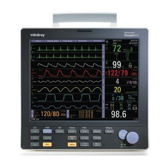
, pulse rate (PR), non-invasive blood pressure (NIBP), invasive blood pressure (IBP), End tidal CO value (EtCO ) and anesthetic gas (AG) of single adult, pediatric, and neonatal patients. FIGURE 1-1 The Passport V Monitor Passport V™ Service Manual 0070-10-0705 1 - 1... -
Page 10: System Connections
1.2.1 Mounting the Patient Monitor The Passport V can be mounted on a wall mount bracket, a rolling stand, or a bedrail hook, which can be ordered optionally. Each type of mounting solution is delivered with a complete set of mounting hardware and instructions. Refer to the documentation delivered with the mounting hardware for instructions on assembling mounts. -
Page 11: Main Unit
A connector for an AC power source (100 to 240 VAC, 50/60Hz). 8. Equipotential lug A connector for common ground with other equipment. Main Unit The Passport V consists of the following: • Input system: keypad, knob, and power switch. • Output system: LCD panel, alarm LED board, recorder, speaker, AC/battery status LEDs). -
Page 12: Input System
The monitor uses an LCD panel with a resolution of 800x600, which runs power and gets digital signals from the CPU board. The backlight is powered by the backlight board, which is powered by the CPU board. 1 - 4 0070-10-0705 Passport V™ Service Manual... - Page 13 CPU to control the LED on the recorder. FPC interface Sends the thermal print head information to the CPU and receives commands from the CPU to control the thermal print head. Passport V™ Service Manual 0070-10-0705 1 - 5...
-
Page 14: Processing And Communications System
Battery interface board The battery interface board serves as an interface between the batteries and the power management and interface board. 1 - 6 0070-10-0705 Passport V™ Service Manual... - Page 15 Pa rame ter boa rd Interfaceboard CF control OEM SpO2 digital circuit board module Backlight LCD digital Wireless board Recorde r circuit Adapter module FIGURE 1-5 DC power system Passport V™ Service Manual 0070-10-0705 1 - 7...
-
Page 16: Equipment Interface System
2 so that the operator can connect a PC to the wired network to configure the wireless adapter. The Ethernet wireless adapter enables the patient monitor to go wireless. FIGURE 1-7 The ethernet wireless adapter 1 - 8 0070-10-0705 Passport V™ Service Manual... - Page 17 Two UART interfaces (serial port 1 and serial port 2) from the CPU board are extended as two RS232-level ports via the power management and interface board. Both interfaces can be configured to accommodate a PC for data or an AG module. FIGURE 1-9 The serial ports Passport V™ Service Manual 0070-10-0705 1 - 9...
-
Page 18: Parameter Modules
UART signal of the OEM SpO modules from other circuits in the main unit. The UART signal comes from the CPU board and passes through the power management and interface board. 1 - 10 0070-10-0705 Passport V™ Service Manual... - Page 19 CIRCUIT FIGURE 1-10 The NIBP module parameter board The Passport V calculates NIBP values using the oscillometric method of noninvasive blood pressure measurement. These measurements correspond to comparisons with auscultatory values, measured using the fifth Korotkoff sound within ANSI/AAMI SP10 standards for accuracy.
- Page 20 Main Unit Theory of Operation This page intentionally left blank. 1 - 12 0070-10-0705 Passport V™ Service Manual...
-
Page 21: Block Diagrams
Wireless AP Module 6100-30-86332 CF card assembly 6100-30-86330 Power Switch with Cable Assembly 6100-21-86306 Speaker 020-000001-00 Fan Assembly 6100-21-86315 NOTE: See Isometric Drawings and Parts List for a complete list of Part Numbers. Passport V™ Service Manual 0070-10-0705 2 - 1... -
Page 22: Block Diagram
Block Diagram FIGURE 2-1 Passport V Block Diagram... -
Page 23: Introduction
Introduction This chapter provides the necessary technical information to perform repairs on the Passport V. The most important prerequisites for effective troubleshooting are a thorough understanding of the instrument functions as well as understanding the theory of operation. Safety Precautions In the event the instrument covers are removed, observe the following warnings and guidelines. -
Page 24: Troubleshooting Guidelines
• Remove all cable assemblies from the left side, right side, and rear of the unit. • Remove any batteries that were installed. • Perform all work on a properly grounded ESD workstation. 3 - 2 0070-10-0705 Passport V™ Service Manual... -
Page 25: Removal Of The Key Panel And Keys
3. Release the key panel’s four clips from the bottom of the unit with a flat-bladed screwdriver. FIGURE 3-2 Release the key panel clips 4. Remove the key panel from the front. 5. Remove the keys and place to the side with the key panel. Passport V™ Service Manual 0070-10-0705 3 - 3... -
Page 26: Removal Of The Front Housing Assembly
3. Turn the unit over and carefully separate the front housing assembly and rear housing assembly. 4. Disconnect the 50-pin ribbon cable from the front housing assembly. FIGURE 3-4 Disconnect the ribbon cable from the front housing assembly 5. Remove the front housing assembly. 3 - 4 0070-10-0705 Passport V™ Service Manual... -
Page 27: Removal Of The Main Board
5. Remove the alarm LED board cable. 6. Remove the five screws that secure the main board to the front housing bracket. 7. Remove the main board carefully. FIGURE 3-5 Remove the main board Passport V™ Service Manual 0070-10-0705 3 - 5... -
Page 28: Removal Of The Inverter
3. Remove the two backlight board cable from the inverter. 4. Remove the two screws that secure the inverter to the front housing bracket. 5. Remove the inverter carefully. FIGURE 3-6 Remove the inverter 3 - 6 0070-10-0705 Passport V™ Service Manual... -
Page 29: Removal Of The Lcd Panel
5. Remove the LCD panel cable. 6. Remove the eight screws that secure the front housing bracket. 7. Remove the front housing bracket and place to the side. FIGURE 3-7 Remove the LCD panel Passport V™ Service Manual 0070-10-0705 3 - 7... -
Page 30: Removal Of The Keyboard
4. Remove the four screws that secure the keyboard to the front housing. 5. Remove the four keyboard pads. 6. Release the clip on the right side of the keyboard and remove the keyboard carefully. FIGURE 3-9 Remove the Keyboard 3 - 8 0070-10-0705 Passport V™ Service Manual... -
Page 31: Removal Of The Alarm Led Board
1. Remove the front housing assembly as stated in “Removal of the Front Housing Assembly” on page 3-4. 2. Remove the encoder cable from the keyboard. FIGURE 3-11 Disconnect the encoder cable Passport V™ Service Manual 0070-10-0705 3 - 9... -
Page 32: Removal Of The Multi-Parameter Board Assembly
2. Disconnect the 50-pin ribbon cable from the interface board. 3. Disconnect the cable from J15 of the interface board. 4. Disconnect the NIBP communication cable from the interface board. FIGURE 3-13 Disconnect the cables from the multi-parameter board 3 - 10 0070-10-0705 Passport V™ Service Manual... - Page 33 5. Remove the four screws that secure the assembly to the rear housing and main frame. 6. Disconnect the CO tubing and cable from the multi-parameter board assembly (if CO module is configured). 7. Remove the multi-parameter board assembly carefully. FIGURE 3-14 Remove the multi-parameter board assembly Passport V™ Service Manual 0070-10-0705 3 - 11...
-
Page 34: Removal Of The Parameter Front Panel Assembly
FIGURE 3-16 Masimo SpO FIGURE 3-17 Nellcor SpO 4. Remove the three screws that secure the parameter front panel. 5. Remove the parameter front panel. FIGURE 3-18 Remove the parameter front panel 3 - 12 0070-10-0705 Passport V™ Service Manual... -
Page 35: Removal Of The Multi-Parameter Board
3. Remove the CO module. FIGURE 3-20 DPM CO FIGURE 3-21 Microstream CO 4. Remove the water trap connector assembly or microstream CO connector fixture assembly from the parameter front panel assembly (if necessary). Passport V™ Service Manual 0070-10-0705 3 - 13... -
Page 36: Removal Of The Masimo Spo Module
4. Unfasten the screw that secures the Nellcor SpO module to the multi-parameter board installation frame. 5. Unfasten the two screws that secure the Nellcor SpO connector. 6. Remove the Nellcor SpO module. FIGURE 3-23 Remove the Nellcor SpO module 3 - 14 0070-10-0705 Passport V™ Service Manual... -
Page 37: Removal Of The Nibp Assembly
1. Remove the two screws that secure the recorder. 2. Release the two clips and pull out the recorder. FIGURE 3-25 Remove the recorder assembly 3. Disconnect the recorder cable. 4. Remove the recorder. Passport V™ Service Manual 0070-10-0705 3 - 15... -
Page 38: Removal Of The Recorder Cover (If Needed)
3. Disconnect the power switch cable from the interface board. 4. Remove the eight screws that secure the main frame and multi-parameter board assembly to the rear housing. FIGURE 3-27 Remove the screws and cables from the main frame 3 - 16 0070-10-0705 Passport V™ Service Manual... -
Page 39: Removal Of The Speaker Assembly
3. Disconnect the speaker cable from the interface board. FIGURE 3-29 Disconnect the speaker cable from the interface board 4. Remove the three screws that secure the speaker. 5. Remove the speaker assembly. FIGURE 3-30 Remove the speaker assembly Passport V™ Service Manual 0070-10-0705 3 - 17... -
Page 40: Removal Of The Fan Assembly
FIGURE 3-31 Disconnect the fan cable from the interface board 4. Remove the fan EVA cushion. 5. Remove the two screws that secure the fan. FIGURE 3-32 Remove the fan assembly 6. Remove the fan. 3 - 18 0070-10-0705 Passport V™ Service Manual... -
Page 41: Removal Of The Cf Card Assembly
Main Frame and Multi-parameter Board Assembly” on page 3-16. 2. Remove the two screws that secure the recorder connecting board and then remove the board. FIGURE 3-34 Remove the screws securing the recorder connecting board Passport V™ Service Manual 0070-10-0705 3 - 19... - Page 42 4. Remove the three screws that secure the power socket support from the back of the main frame. 5. Remove the screw that secures the grounding wire. FIGURE 3-36 Remove the screws that secure the power socket 3 - 20 0070-10-0705 Passport V™ Service Manual...
-
Page 43: Removal Of The Li-Ion Battery Interface Board Assembly
2. Remove the recorder assembly (if installed) as stated in “Removal of the Recorder Assembly” on page 3-15. 3. Remove the two screws that secure the recorder connecting board and then remove the board. FIGURE 3-38 Remove the screws securing the recorder connecting board Passport V™ Service Manual 0070-10-0705 3 - 21... - Page 44 FIGURE 3-39 Disconnect the Li-ion battery interface board cable 5. Remove the four nuts that secure the Li-ion battery interface board assembly. 6. Remove the Li-ion battery interface board assembly. FIGURE 3-40 remove the Li-ion battery interface board assembly 3 - 22 0070-10-0705 Passport V™ Service Manual...
-
Page 45: Removal Of The Interface Board Assembly
FIGURE 3-42 Remove the screws securing the main frame 7. Disconnect the Li-ion battery interface board cable from the interface board. 8. Disconnect the power cable from the interface board. 9. Disconnect the recorder cable from the interface board. Passport V™ Service Manual 0070-10-0705 3 - 23... - Page 46 FIGURE 3-44 Disconnect the cables from the interface board 14. Remove the two screws that secure the interface board assembly to the main frame. 15. Remove the interface board assembly. FIGURE 3-45 Remove the interface board assembly 3 - 24 0070-10-0705 Passport V™ Service Manual...
-
Page 47: Removal Of The Wireless Ap
FIGURE 3-46 Remove the screws from the main frame 5. Remove the two screws that secure the main frame from the bottom. 6. Remove the main frame assembly. FIGURE 3-47 Remove the screws securing the main frame Passport V™ Service Manual 0070-10-0705 3 - 25... - Page 48 FIGURE 3-48 Remove the nut securing the wireless AP to the main frame 8. Disconnect the wireless AP cable from the wireless AP. 9. Remove the wireless AP. FIGURE 3-49 Disconnect the cables from the wireless AP 3 - 26 0070-10-0705 Passport V™ Service Manual...
-
Page 49: Nurse Call Cable
Repair Information Nurse Call Cable Nurse Call Cable 3.6.1 P/N 8000-21-10361 FIGURE 3-50 Nurse Call Cable Analog Output Cable 3.7.1 P/N 6100-20-86360 FIGURE 3-51 Analog Output Cable Passport V™ Service Manual 0070-10-0705 3 - 27... -
Page 50: Defib Synch Cable
Defib Synch Cable Repair Information Defib Synch Cable 3.8.1 P/N 6100-20-86361 FIGURE 3-52 Defib Synch Cable 3 - 28 0070-10-0705 Passport V™ Service Manual... -
Page 51: Serial Port To Gas Module 3 Cable
Serial Port to Gas Module 3 Cable 3.9.1 P/N 0012-00-1276-XX DESCRIPTION DASH NUMBER 12" 9-pin mini-D serial to 25-pin D-shell 72" 9-pin mini-D serial to 25-pin D-shell FIGURE 3-53 Serial Port to Gas Module 3 Cable Passport V™ Service Manual 0070-10-0705 3 - 29... -
Page 52: Null Modem Cable
Null Modem Cable Repair Information 3.10 Null Modem Cable 3.10.1 P/N 0012-00-1275-01 FIGURE 3-54 Null Modem Cable 3 - 30 0070-10-0705 Passport V™ Service Manual... -
Page 53: Universal Ecg Lead Wires
DASH # 10 24", snap, 5-lead set, Domestic 11 24", snap, 3-lead set, Domestic 12 24", snap, 5-lead set, International 13 24", snap, 3-lead set, International FIGURE 3-55 Universal ECG Lead Wires Passport V™ Service Manual 0070-10-0705 3 - 31... -
Page 54: Ecg Cable, 3/5-Lead (Esis And Non Esis)
3.12.1 P/N 0012-00-1745-XX FIGURE 3-56 ECG Cable, 3/5-lead (ESIS and Non ESIS) 3.13 12-pin 3-lead Neo ECG Trunk Cable (IEC/AHA) 3.13.1 P/N 040-000072-00 FIGURE 3-57 12-pin 3-lead Neo ECG Trunk Cable (IEC/AHA) 3 - 32 0070-10-0705 Passport V™ Service Manual... -
Page 55: Ibp Cable
IBP Cable 3.14.1 P/N 040-000052-00 FIGURE 3-58 5-pin IBP Cable (IM2301, Hospira) 3.14.2 P/N 040-000053-00 FIGURE 3-59 5-pin IBP Cable (IM2302, BD) 3.14.3 P/N 040-000054-00 FIGURE 3-60 5-pin IBP Cable (IM2303, Edwards) Passport V™ Service Manual 0070-10-0705 3 - 33... -
Page 56: P/N 040-000096-00
FIGURE 3-61 IBP Adapter Cable (5-pin to 6-pin) 3.15 Temperature Cable 3.15.1 1.15.1 P/N 040-000055-00 FIGURE 3-62 5-pin Esophageal/Rectal Temp Probe (Adult) 3.15.2 P/N 040-000056-00 FIGURE 3-63 5-pin Esophageal/Rectal Temp Probe (Pediatric/Infant) 3 - 34 0070-10-0705 Passport V™ Service Manual... -
Page 57: P/N 040-000057-00
P/N 040-000057-00 FIGURE 3-64 5-pin Skin Temp Probe (Adult) 3.15.4 P/N 040-000058-00 FIGURE 3-65 5-pin Skin Temp Probe (Pediatric/Infant) 3.15.5 P/N 040-000091-00 FIGURE 3-66 5-pin Temp Cable for 400 Series Disposable Sensor Passport V™ Service Manual 0070-10-0705 3 - 35... -
Page 58: P/N 040-0000100-00
Temperature Cable Repair Information 3.15.6 P/N 040-0000100-00 FIGURE 3-67 5-pin Temp Adapter Cable (5-pin to 6.35 Phone) 3.15.7 P/N 040-000224-00 FIGURE 3-68 5-pin Temp Cable for MRS Disposable Sensor (5.5 DC Jack) 3 - 36 0070-10-0705 Passport V™ Service Manual... -
Page 59: Troubleshooting Menus
Readjust as required (Set via the Size key). Lead wires and patient cable not fully or properly Check for proper inserted. insertion. Cable or lead wires Check with lead damaged. continuity tester. Passport V™ Service Manual 0070-10-0705 3 - 37... - Page 60 When Pace Reject is set to Off, this message disappears. Learning Displayed when a learning cycle has been requested for Arrhythmia or ST. No Arrhythmia Detection at Central Station does not Central have arrhythmia Analysis capability. 3 - 38 0070-10-0705 Passport V™ Service Manual...
-
Page 61: Nibp Troubleshooting
Retry measurement. If automatic retries. message reappears, power cycle unit. If message reappears, contact Technical Support. NIBP: Reset Failed Reset failed. Power cycle unit.If message reappears, contact Technical Support. Passport V™ Service Manual 0070-10-0705 3 - 39... -
Page 62: Spo Troubleshooting
Change or readjust sensor if loose. : No Pulse (DPM/Nellcor No detectable pulse is Check to patient Only) measured. connection and patient status. 3 - 40 0070-10-0705 Passport V™ Service Manual... - Page 63 Menu, choose to display Pleth in the waveform Cable or sensor not area. plugged in. Check cable and sensor. : Initialization Error No response after send Contact Technical order during Support. initialization. Passport V™ Service Manual 0070-10-0705 3 - 41...
-
Page 64: Temperature Troubleshooting
A calibration failed. Restart the monitor. Contact Technical Support. Temp: Initialization Error During the Temperature Contact Technical module power-on, as the Support. Temperature module communication stops, system fails to communicate with module. 3 - 42 0070-10-0705 Passport V™ Service Manual... -
Page 65: Resp Troubleshooting
Check the Patient HR and patient. respiratory rate identical. Resp: Initialization Error During the Resp module Contact Technical power-on, as the Resp Support. module communication stops, system fails to communicate with module. Passport V™ Service Manual 0070-10-0705 3 - 43... -
Page 66: Ibp Troubleshooting
IBP IBP channel. channel. Initialization Error During the IBP module Contact Technical power-on, as the IBP Support. module communication stops, system fails to communicate with module. 3 - 44 0070-10-0705 Passport V™ Service Manual... -
Page 67: Co 2 Troubleshooting
Check the CO (DPM only) too high (higher than connections, make sure 790mmHg). that the monitor application site meets the requirements, and check for special sources that affect the ambient pressure. Restart the monitor. Passport V™ Service Manual 0070-10-0705 3 - 45... - Page 68 5 or above Apply cooling or heating if possible. : Check Sensor Possible Faulty sensor. Replace the module. (Microstream only) Contact Technical Support. 3 - 46 0070-10-0705 Passport V™ Service Manual...
- Page 69 Technical Support. Caused by no stable gas flow No stable gas flow Check the gas (Microstream only) connections or gas concentration. Repeat calibration procedure. If problem persists, contact Technical Support. Passport V™ Service Manual 0070-10-0705 3 - 47...
-
Page 70: Gas Module Troubleshooting
Technical Support. sensor. GM: O Zero Error Appears when the system Manually start zeroing has been unable to the system again. If successfully zero the O problem persists, contact Technical Support. sensor. 3 - 48 0070-10-0705 Passport V™ Service Manual... - Page 71 Technical Support. GM: Pump Off Appears when the system Restart the pump from the has turned off the pump Gas Menu. If problem due to a pneumatic error. persists, contact Technical Support. Passport V™ Service Manual 0070-10-0705 3 - 49...
-
Page 72: Trends Troubleshooting
Local Printer Door Open The printer door is not Close the printer door. closed. Local Printer Out Of Paper Printer out of paper. Replace with a new roll of paper. 3 - 50 0070-10-0705 Passport V™ Service Manual... - Page 73 Passport V monitor. Remote Printer Not Available This message is displayed Fix the printer. in the case of a printer error. Passport V™ Service Manual 0070-10-0705 3 - 51...
-
Page 74: Monitor/Display Troubleshooting
A patient monitor can only be viewed by 4 Incorrect IP configuration. other patient monitors at the same time. The excessive view requests system will be ignored. Check for IP address conflict. Reconfigure IP address. 3 - 52 0070-10-0705 Passport V™ Service Manual... -
Page 75: Installation Menu
2. Set each item as necessary. The operation of the menu is the same as that of the normal operating mode. To save all of the selected settings, choose Save Current before exiting this menu. To access the normal operation screen, power the unit OFF and ON again. Passport V™ Service Manual 0070-10-0705 3 - 53... - Page 76 Nurse Call Mode Normally Open, Normally Open Select to change Normally Close Nurse Call Mode. Set up Serial Port 1 None, DIAP, Gas None Select to set up a Module serial output protocol port. 3 - 54 0070-10-0705 Passport V™ Service Manual...
- Page 77 Discharge key while powering on the monitor. 6. Select Copy Monitor Defaults from Storage Device. A status message will report completion of the transfer. 7. Select Save Current and power-cycle the receiving monitor to enter normal monitoring mode. Passport V™ Service Manual 0070-10-0705 3 - 55...
-
Page 78: Advanced Installation Setup Menu
255.255.255.0 Select to set up Subnet Mask ID. Configure Wireless Select to configure wireless AP. Search Printer Select to search printer. Paper Size A4, Letter Select to change paper size. Device ID 3 - 56 0070-10-0705 Passport V™ Service Manual... -
Page 79: Options Menu
3.18 Trend Storage The Passport V monitor is capable of storing, in non-volatile memory, up to 6000 trend data entries. When the maximum number of entries has been reached, the oldest entry will be deleted to allow storage of new data. -
Page 80: Software Download
Expiration column. If Update is selected again before update is complete, updating will be cancelled and “/” will be displayed. Updating by DPM SB storage device can only be used to enable certain system functions. 3 - 58 0070-10-0705 Passport V™ Service Manual... -
Page 81: Isometric Drawings And Parts List
Isometric Drawings and Parts List Introduction This chapter provides information necessary to identify the replacement parts and assemblies of instruments. Passport V™ Service Manual 0070-10-0705 4 - 1... -
Page 82: Top Level Assembly
Top Level Assembly Isometric Drawings and Parts List Top Level Assembly FIGURE 4-1 Top Level Assembly 4 - 2 0070-10-0705 Passport V™ Service Manual... - Page 83 6100-20-86265-56 Keypad, Brazilian Portuguese 6100-20-86265-57 Label, Patient Connector, All 6100-20-86316-51 Label, Patient Connector, Basic 6100-20-86346-51 Label, Patient Connector, ECG/NIBP/T1/IBP 6100-20-86347-51 Label, Patient Connector, ECG/NIBP/T1/CO 6100-20-86348-51 Label, Product Information 6100-20-86317 Bedrail Hook 801-6100-00001-00 Passport V™ Service Manual 0070-10-0705 4 - 3...
-
Page 84: Main Unit Assembly
Screw, Pan Head Phillips M3X6 M04-002505--- Sub-assembly, Rear Housing AC Inlet Hook 9211-20-87369 Screw, Flat Head Phillips M3X8 M04-000405--- Sub-assembly, Main Chassis Microstream CO Module Assembly 801-6100-00029-00 DPM CO Module Assembly 801-6100-00030-00 Sub-Assembly, Parameter board subassembly 4 - 4 0070-10-0705 Passport V™ Service Manual... -
Page 85: Front Housing Sub-Assembly
LCD,TFT 12.1" 800x600 3.3V 801-0000-00005-00 Screw, Flat Head Phillips M3X6 M04-005005--- Cable Assembly, Mainboard to Keypad PCBA 6100-20-86304 Cable Assembly, LCD to Mainboard 6100-20-86340 Cable Assembly, Inverter to Mainboard 9211-20-87235 Overlay, Alarm Light 6100-20-86268 Passport V™ Service Manual 0070-10-0705 4 - 5... -
Page 86: Rear Housing Sub-Assembly
Rear Housing Sub-assembly Isometric Drawings and Parts List Rear Housing Sub-assembly FIGURE 4-4 Rear Housing Sub-assembly ITEM NO DESCRIPTION PART NUMBER Handle service kit 801-6100-00009-00 Rear Housing service kit 801-6100-00010-00 Foot DA6H-20-22831 4 - 6 0070-10-0705 Passport V™ Service Manual... -
Page 87: Main Chassis Sub-Assembly
Main Chassis Sub-assembly FIGURE 4-5 Main Chassis Sub-assembly... - Page 88 Screw, Flat Head Self-Tapping PT3X8 Bracket, Main Battery latch retaining plate Spring, EMI 0000-10-10996 PCBA, Li-Battery 801-6100-00016-00 Nut, Lock WasherM3 Cable Assembly, Recorder 9211-20-87228 Plate, Recorder Mounting Screw, Pan Head W/Washer Phillips M3X6 M04-004012--- 4 - 8 0070-10-0705 Passport V™ Service Manual...
-
Page 89: Interface Connector Pcb Assembly
PCBA, Power Supply Management and Interface Use assembly P/N 801-6100-00025-00 Bracket, Interface Board Top Bracket, Interface Board Bottom Gasket, Network Socket 9211-20-87440 Screw, Pan Head W/Washer Phillips M3X6 M04-004012--- Spring, EMI 0000-10-10996 Passport V™ Service Manual 0070-10-0705 4 - 9... -
Page 90: Parameter Sub-Assembly
Frame, Parameter Board Mounting 6100-20-86276 Cable Assembly, NIBP 6100-20-86305 NIBP Module Assembly 801-6100-00026-00 Masimo SpO Module Assembly 801-6100-00028-00 Nellcor SpO Module Assembly 801-6100-00027-00 DPM SpO Module Assembly 801-6100-00024-00 Sub-assembly, Patient Connector 801-6100-00018-00 4 - 10 0070-10-0705 Passport V™ Service Manual... -
Page 91: Patient Connector Sub-Assembly
Opening 6100-20-86297 Watertrap assembly, Sidestream CO See DPM CO Module Assembly Assembly, Micro-stream CO Receptacle 801-6100-00020-00 Gas Outlet 6200-20-11614 Assembly, NIBP Connector DA6H-20-22833 Parameter Connector Panel 6100-30-86328 Nut, Stainless Steel M5 GB6170 Passport V™ Service Manual 0070-10-0705 4 - 11... -
Page 92: Nibp Module Assembly
Tubing, Silicone, Five Branch Screw, Pan Head Phillips M3X6 TUBE. Silicone, 1/8" X 1/4" X100ft,2800546-100 A21-000002--- Pump 801-6101-00014-00 Cushion, Pump 6101-20-46761 Cable Assembly, NIBP 6100-20-86305 Screw, Self-Tapping PT2.6X6 Screw, Flat Head Phillips M2X4 4 - 12 0070-10-0705 Passport V™ Service Manual... -
Page 93: Microstream Co Module Assembly
Bracket, Micro-Stream CO Mounting Cable Assembly, Micro-Stream CO to Transfer Board 9201-20-35932 PCBA, Micro-Stream CO Transfer Cable Assembly, Micro-Stream CO 9211-20-87247 Screw, Pan Head Phillips M3X6 Module, Micro-Stream CO Assembly, Micro-stream CO Receptacle 801-6100-00020-00 Passport V™ Service Manual 0070-10-0705 4 - 13... -
Page 94: Dpm Co 2 Module Assembly
Tubing( ID 1/16’ OD 1/8’) (20feet) 3001-10-07069 Flush Mount, Water Trap 040-000225-00 Flow restrictor tube M02A-21-25944 Cable Assembly, Watertrap cable 009-000101-00 Module, CO Host (M02B) Screw, Pan Head W/Washer Phillips M3X6 M04-004012--- 4 - 14 0070-10-0705 Passport V™ Service Manual... -
Page 95: Masimo Spo Pcb Assembly
Nut, Stainless Steel M3 GB6170 Washer, insulating 3X1mm flex cable assembly 2685 040-000150-00 Screw, Flat Head PhillipsM2.5X4 Frame, Masimo SpO Connector 6101-20-46720-52 Screw, Self-Tapping PT3X8 Screw, Pan Head Phillips M3X6 Masimo MS-2013 board 801-6101-00016-00 Passport V™ Service Manual 0070-10-0705 4 - 15... -
Page 96: Nellcor Spo Module Assembly
Nut, Stud M3X12 Screw, Phillips Pan Head Washer M3X18 Isolated power and signal conversion board PCBA, 801-6101-00017-00 Nellcor SpO module Communication cable. OEM SpO 9211-20-87242 Screw, Pan Head W/Washer Phillips M3X6 M04-004012--- 4 - 16 0070-10-0705 Passport V™ Service Manual... -
Page 97: Introduction
The following procedures are provided to verify the proper operation of the Passport V Monitor. Service Diagnostics provides the capability of diagnosing problems within the Passport V hardware. A menu driven interface, similar to that of the Passport V user interface, is used to execute all tests. -
Page 98: Test Equipment And Special Tools Required
3. Rotate the Navigator Knob to move the cursor within the Service Menu. Pressing the Navigator Knob will select the desired test and open the second test menu. FIGURE 5-1 Service Menu 5 - 2 0070-10-0705 Passport V™ Service Manual... -
Page 99: Ecg Channels Check
Knob to select the Start Channels Check button and activate the test. A square wave should appear on the screen. 3. Compare the amplitude of the square wave with the wave scale. The difference should be within 5%. Passport V™ Service Manual 0070-10-0705 5 - 3... -
Page 100: Nibp Maintenance
The difference between readings should not be greater than +/-3 mmHg. NOTE: An NIBP simulator can be used to replace the reference manometer with the bulb valve to perform the test. Specifications: 0 to 300 mmHg +/- 3 mmHg 5 - 4 0070-10-0705 Passport V™ Service Manual... -
Page 101: Nibp Leakage Test
NOTE: If the calibration is successful, the calibration time will be displayed in the format of year, month, day, hour, and minute. Otherwise, the calibration time is displayed as dashes. Passport V™ Service Manual 0070-10-0705 5 - 5... -
Page 102: Ibp Calibration
CO readings appear suspicious. The date of the last successful calibration appears on the Calibration CO Menu. The CO module must be warmed up before calibration. 5 - 6 0070-10-0705 Passport V™ Service Manual... - Page 103 7. If the calibration is successful, the message “Calibration Completed Successfully” appears. Otherwise, the message “Calibration Failure” appears. If so, another calibration is required. FIGURE 5-6 Sidestream CO Calibrate Menu Passport V™ Service Manual 0070-10-0705 5 - 7...
-
Page 104: Gas Calibration
If the Gas Module fails zeroing, a zeroing error will be displayed and the previous calibration data will be restored. If so, repeat the calibration procedure from step 1. If problems persist, contact Customer Support. 5 - 8 0070-10-0705 Passport V™ Service Manual... - Page 105 Calibration Error message will appear after the Accept button is selected. The Gas Module 3 will not accept span calibration with errors in any channel. FIGURE 5-8 Gas Calibration Passport V™ Service Manual 0070-10-0705 5 - 9...
- Page 106 Services Calibration Procedure FIGURE 5-9 Calibration 5 - 10 0070-10-0705 Passport V™ Service Manual...
-
Page 107: Monitor Log
2. Errors log will appear on screen. Each error is time stamped and dated. 3. Use the Navigator Knob to move the cursor within the list of errors. 4. To clear all data from the error log, use the Navigator Knob to select Clear. Passport V™ Service Manual 0070-10-0705 5 - 11... -
Page 108: Verification
IBP2 – Scale 0 to 80 mmHg 3. SpO a. Averaging mode – 2 b. Sensor Off Audio – off 4. CO (optional) a. Apnea Delay – 60 b. Scale 40 mmHg 5 - 12 0070-10-0705 Passport V™ Service Manual... -
Page 109: Ecg
1. Set the simulator to 1mv ECG QRS signal, rate set to 60 bpm. 2. Set to Print on Alarm, install paper in the recorder, and set the Low HR alarm to 50 bpm, and High alarm to 120 bpm. Passport V™ Service Manual 0070-10-0705 5 - 13... -
Page 110: Performance Test
5.5.6 NIBP Verification 1. Connect the Adult cuff connector to the NIBP hose. Attach the NIBP hose to the Cuff connection on the left side of the monitor. 5 - 14 0070-10-0705 Passport V™ Service Manual... -
Page 111: Battery Operation Verification
500 µA under a single fault condition for 230 VAC Patient Leakage 1. Lead to ground: Sink Current Patient circuit (Test V, Model 431 Dempsey; patient leakage with line voltage on leads). Passport V™ Service Manual 0070-10-0705 5 - 15... - Page 112 4. On the safety analyzer depress the Apply 115 VAC button and note the reading. 5. Repeat the test for normal and open ground polarity combinations. Specifications: Verify the current readings of the test are below 50µA under a single fault condition. 5 - 16 0070-10-0705 Passport V™ Service Manual...
-
Page 113: Preventative Maintenance
Preventative Maintenance User Preventative Maintenance Introduction This chapter outlines routine user maintenance guidelines. The Passport V Monitor is designed for stable operation over long periods of time. Under normal circumstances, the monitor should not require technical maintenance beyond that described in this chapter. -
Page 114: Preventative Maintenance Schedule
Preventative Maintenance Preventative Maintenance Schedule The following is a list of activities required for periodic maintenance of the Passport V monitor. The physical inspection, replacement of consumable items, and performance checks should be performed at the recommended intervals stated below. Mindray DS USA, Inc. is not responsible for component failure or loss resulting from the use of stated consumable items beyond their recommended replacement interval. -
Page 115: Perform Verification And Gas Calibration - Annually
1. Perform temperature test. See “Temperature Verification” on page 5-14. 6.2.10 Perform Verification – Annually 1. Perform SpO test. See “SpO2 Verification” on page 5-14. 6.2.11 Electrical Safety Tests – Annually 1. Perform test. See “Leakage Current Tests” on page 5-15. Passport V™ Service Manual 0070-10-0705 6 - 3... -
Page 116: Care And Cleaning Of The Monitor
(paper based) and wipe down the outside of the unit. Discard the wipe appropriately. After waiting 10 minutes, use a clean dry wipe to dry the unit. CAUTION: When cleaning the monitor, do not allow cleaning solutions into the vent openings. 6 - 4 0070-10-0705 Passport V™ Service Manual... -
Page 117: Care And Cleaning Of Spo Sensors
70% alcohol. Do not sterilize by irradiation, steam, ® or ethylene oxide. Use a new Oxiband adhesive wrap or FORM-A adhesive bandage for ® ® each patient. Do not re-sterilize Oxisensor or OxiMax oxygen transducers. Passport V™ Service Manual 0070-10-0705 6 - 5... -
Page 118: Cleaning Co 2 Sensors, Adapters And Sampling Components
Sensors, Adapters and Sampling Components Preventative Maintenance Cleaning CO Sensors, Adapters and Sampling Components Microstream CO patient monitoring accessories are designed for single patient use and should not be cleaned or reused. 6 - 6 0070-10-0705 Passport V™ Service Manual... -
Page 119: Sterilization And Cleaning Of Cuffs
Do not dry clean the cuff. Do not press the cuff with a hot iron. Do not use detergent and disinfectant other than fresh water or 70% isopropanol. Clean and disinfect the cuff according to the instructions. Passport V™ Service Manual 0070-10-0705 6 - 7... -
Page 120: Reusable Bladderless Cuffs
Do not use the same cuff on any other patient. Do not sterilize or use an autoclave on disposable cuffs. CAUTION: Disposable cuffs can be cleaned using a mild soap solution and dried with a clean cloth. 6 - 8 0070-10-0705 Passport V™ Service Manual... -
Page 121: Care And Cleaning Of Gas Module
Do not disinfect or open the water trap. If an occlusion message appears it may be necessary to replace the water trap assembly part number 0202-00-0129. The Water Trap Assembly must be replaced every two months. Passport V™ Service Manual 0070-10-0705 6 - 9... -
Page 122: Care And Cleaning Of 3- And 5-Lead Ecg Cables And Leadwires
Do not autoclave, radiation or steam sterilize ECG cables or leadwires. NOTE: Extended exposure to Ethylene Oxide gas may shorten life of the ECG cables and leadwires, leading to poor signal quality. 6 - 10 0070-10-0705 Passport V™ Service Manual... -
Page 123: Battery Replacement And Maintenance
CAUTION: Recharge batteries in the Passport V . CAUTION: Remove the batteries if the Passport V is not likely to be used for an extended period of time. Lithium-Ion Storage of the lithium-ion batteries depends on temperature, time period and the degree of cell charging state. -
Page 124: Recorder Maintenance
6.10 Recorder Maintenance 6.10.1 Cleaning the Recorder Printhead If the recorder has been used for a long time, deposits of paper debris may collect on the printhead, compromising the print quality and shortening the life of the roller. Follow this procedure to clean the printhead: 1. - Page 125 We recommend that if long term archives are required, make a photocopy of the recordings as back-up. Under normal office filing conditions, the recordings should retain acceptable image quality for about five years Passport V™ Service Manual 0070-10-0705 6 - 13...
-
Page 126: Warranty Statements
6.11 Warranty Statements Mindray DS USA, Inc. warrants that components within the monitor unit will be free from defects in workmanship and materials for the number of years shown on the Mindray invoice. Under this extended warranty, Mindray DS USA, Inc. will repair or replace any defective component at no charge for labor and/or materials. -
Page 127: International (Excluding North America)
6.11.2 International (excluding North America) Mindray DS USA, Inc. warrants that its products will be free from defects in workmanship and materials for a period of two (2) years from the date of purchase except that disposable or one-time use products are warranted to be free from defects in workmanship and materials up to a date one year from the date of purchase or the date of first use, whichever is sooner. -
Page 128: Phone Numbers And How To Get Help
6.11.4 Manufacturer’s Responsibility Mindray DS USA, Inc. is responsible for the effects on safety, reliability and performance of the equipment only if: a. Assembly operations, extensions, readjustments, modifications or repairs are carried out by persons authorized by Mindray; and b. - Page 129 Preventative Maintenance Warranty Statements This page intentionally left blank. Passport V™ Service Manual 0070-10-0705 6 - 17...
- Page 130 Printed in U.S.A. 0070-10-0705 Rev A December 3, 2009...
- Page 131 Tel: +31 33 25 44 911 • Fax: +31 33 25 37 621 Mindray (UK) Limited • 3 Percy Road • St. John’s Park • Huntingdon • Cambridgeshire PE29 6SZ • United Kingdom • Tel: 01480 416840 • Fax: 01480 436588 Mindray Medical France SARL •...
Need help?
Do you have a question about the Passport V and is the answer not in the manual?
Questions and answers