
Related Manuals for AMI 217 WDR

Summary of Contents for AMI 217 WDR
- Page 1 Model 217 WDR Tube Welding Power Supply Operator’s Manual Part No. 740126 Revision A...
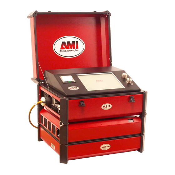
- Page 2 Model 217 WDR is a power source and controller for automatic orbital tube welding. It is intended to be used only in conjunction with AMI and EXEL by AMI orbital tube welding heads and accessories. The Model 217 WDR power supply...
-
Page 3: Table Of Contents
POWER SUPPLY CONNECTION ..............12 POWER UP ...................... 13 LIBRARY AND MEMORY ................14 LOADING A WELD SCHEDULE FROM THE MODEL 217 WDR LIBRARY . 15 COPYING WELD SCHEDULES FROM THE MODEL 217 WDR TO AN EXTERNAL MEMORY DEVICE ..............18 COPYING WELD SCHEDULES FROM AN EXTERNAL MEMORY DEVICE TO THE MODEL 217 WDR LIBRARY ............. - Page 4 M O D E L 2 1 7 W D R O P E R A T O R ’ S M A N U A L MAINTENANCE AND TROUBLESHOOTING ..........44 GENERAL MAINTENANCE ................44 TROUBLESHOOTING ..................45 AMI OFFICES ....................47...
-
Page 5: Safety Precautions
1.0 SAFETY PRECAUTIONS The Model 217 WDR is intended to be used only with AMI or EXEL by AMI weld heads for the purpose of GTAW welding of metal tube. The system is not to be used for any other purpose, specifically heating or cutting. - Page 6 O P E R A T O R ’ S M A N U A L The Model 217 WDR is intended to be used only with AMI and EXEL by AMI weld heads for the purpose of GTAW welding of metal tube or pipe. The system is not to be used for any other purpose, specifically heating or cutting.
-
Page 7: Warning Label Definitions
M O D E L 2 1 7 W D R O P E R A T O R ’ S M A N U A L 1.2 WARNING LABEL DEFINITIONS The table below contains caution and warning labels for the operation of this equipment. Before operating this or any welding equipment users should be familiar with “ANSI-49.1 Safety in Welding and Cutting”. - Page 8 O P E R A T O R ’ S M A N U A L WARNING: Exel factory training is essential for all Welding Operators and Maintenance Technicians who operate AMI or EXEL by AMI equipment. WELDING WIRE and ELECTRODES are sharp and can cause injury.
-
Page 9: System Symbols
Ethernet port. For networking capability. Devices should not be left plugged in while welding. Remote control connection. Weld head electrode and ground connections. Output for the arc shielding gas connection. Weld head control. Intended for AMI and EXEL by AMI weld heads only. -
Page 10: Specifications
The Model 217 WDR is a mobile system that is intended to be hand carried. The supporting equipment such as weld heads, water coolers, gas regulators, remote controls and extension cables can also be hand carried. -
Page 11: Electrical Service Guide
CIRCUIT BREAKER – ON/OFF, two pole, 30 Ampere at 250 VAC. DUTY CYCLE – determined by the AC input voltage and the required output current. The Model 217 WDR system has an internal thermal sensor that will limit operation should the temperature exceed the safe operating parameters. -
Page 12: Programmable And Operational Functions
M O D E L 2 1 7 W D R O P E R A T O R ’ S M A N U A L 2.4 PROGRAMMABLE AND OPERATIONAL FUNCTIONS SINGLE ENTRY PARAMETERS AND FUNCTIONS FUNCTION RANGE WELD TYPE (PULSED, NON-PULSED, STEP, SELECTABLE TACK, S^3) NUMBER OF LEVELS... - Page 13 M O D E L 2 1 7 W D R O P E R A T O R ’ S M A N U A L MULTI-LEVEL PARAMETERS AND FUNCTIONS (con’t) BACKGROUND SPEED (RPM) 0.0 RPM TO WELD HEAD MAX.** BACKGROUND SURFACE SPEED CALCULATED AVERAGE SPEED...
-
Page 14: Start Up
3.0 START-UP 3.1 REQUIRED PERIPHERALS 1. An orbital weld head is required to weld with the Model 217 WDR. Shown below is the EXEL by AMI RDR-05 Rotor Driver and an AMI Model 9-750 orbital weld head. 2. An A.C. power cord rated for 600 VAC service (below left) and gas purge lines are provided to connect power and inert gas to the power supply. -
Page 15: Optional Periferals
All AMI power supplies have their own respective optional remote pendant. This gives the operator remote welding functions of the Model 217 WDR power supply itself. The optional cooling unit is recommended for high production or heavy walled (.109”-.154”) welding applications. -
Page 16: Power Supply Connection
M A N U A L 3.3 POWER SUPPLY CONNECTION 1. Below is a view of the input and output sides of the Model 217 WDR Power Supply with all connectors visible. Connect the A.C. power cord into a utility power source ranging from 115/230 volts, 50/60 hertz single phase. -
Page 17: Power Up
SHUT DOWN the power supply. MAIN SCREEN Touch LIBRARY pad to open the Model 217 WDR’s internal library which can store over 1,000 complete weld schedules. Each schedule having up to 100 individual levels allowing for precise manipulation of weld parameters to achieve optimum results based upon your... -
Page 18: Library And Memory
COPY weld schedules to/from an external memory device. LIBRARY These modes are enabled and displayed only when a memory storage device is connected to the Model 217 WDR’s USB port(s). The Model 217 WDR’s Library shows the weld schedules available and displays them by: ... -
Page 19: Loading A Weld Schedule From The Model 217 Wdr Library
4.1 LOADING A WELD SCHEDULE FROM THE MODEL 217 WDR LIBRARY 1. Flip the main power switch (CB-1) of the Model 217 WDR to the ON position. 2. Once the computer boots up touch LIBRARY on the MAIN SCREEN. 3. Peruse the LIBRARY, touch the desired weld schedule on the screen, it will become highlighted. - Page 20 M O D E L 2 1 7 W D R O P E R A T O R ’ S M A N U A L WELD SCREEN From the Weld Screen the operator has access to all power supply, welding and weld head functions at a touch of the weld screen: START: Starts the Weld sequence.
- Page 21 M O D E L 2 1 7 W D R O P E R A T O R ’ S M A N U A L POWER ADJUST: This value establishes the min/max % adjustment that the operator can make to the welding current. On the Weld screen the operator can then adjust the welding current up or down in 0.1% increments to this value.
-
Page 22: Copying Weld Schedules From The Model 217 Wdr To An External Memory Device
COPY ALL TO EXTERNAL MEMORY if you want the entire Model 217 WDR library copied to the external memory device. Note: Should the weld schedule(s) you are trying to copy from the Model 217 WDR library already exist in the external memory device the following screen be displayed:... - Page 23 4. The screen below will be displayed to verify if one weld schedule was copied successfully to the external memory device. 5. OR the screen below will be displayed to verify if the entire Model 217 WDR library has been copied successfully to the external memory device.
- Page 24 M O D E L 2 1 7 W D R O P E R A T O R ’ S M A N U A L 6. Touch OK to clear verification screen. Touch EXTERNAL MEMORY display. 7. Verify that the weld schedule or schedules have been copied to the external memory device.
-
Page 25: Copying Weld Schedules From An External Memory Device To The Model 217 Wdr Library
2. Touch EXTERNAL MEMORY to open and display external memory device library. 3. Select (highlight) one weld schedule to be copied to the Model 217 WDR library. 4. Touch COPY TO M217 WDR to copy that one weld schedule, or touch COPY ALL TO M217 WDR if you want the entire external memory library copied to the Model 217 WDR library. - Page 26 5. The screen below will be displayed to verify if one weld schedule was copied successfully to the Model 217 WDR library. 6. OR the screen below will be displayed to verify if the entire external memory library has been copied successfully to the Model 217 WDR library. ALL SCHEDULES COPIED TO M217.
- Page 27 O P E R A T O R ’ S M A N U A L 7. Touch OK to clear verification screen. Touch M217 WDR display. 8. Verify that the weld schedule or schedules have been copied to the Model 217 WDR library. 9. Remove external memory device.
-
Page 28: Creating Weld Schedules
M O D E L 2 1 7 W D R O P E R A T O R ’ S M A N U A L Chapter 5.0 CREATING WELD SCHEDULES 5.1 CREATING A MANUAL 4 LEVEL WELD SCHEDULE 1. - Page 29 M O D E L 2 1 7 W D R O P E R A T O R ’ S M A N U A L 3. Press Page 2. Select and enter all required LEVELS, PURGE and MOTOR parameters.
- Page 30 7. Pressing SAVE will store all data in the library under the SCHEDULE NAME you selected and the WELD SCREEN will be displayed with the schedule name on top. 8. The Model 217 WDR is now loaded with the weld schedule and is in STANDBY mode, ready to weld.
-
Page 31: Creating An Auto 4 Level Weld Schedule
M O D E L 2 1 7 W D R O P E R A T O R ’ S M A N U A L 5.2 CREATING AN AUTOMATIC 4 LEVEL WELD SCHEDULE 1. From the MAIN SCREEN touch the CREATE SCHEDULE pad and the create schedule menu will be displayed. - Page 32 5. Pressing SAVE will store all data in the library under the SCHEDULE NAME you selected and the WELD SCREEN will be displayed with the schedule name on top. 6. The Model 217 WDR is now loaded with the weld schedule and is in STANDBY mode, ready to weld.
-
Page 33: Creating An Auto Step Weld Schedule
M O D E L 2 1 7 W D R O P E R A T O R ’ S M A N U A L 5.3 CREATING AN AUTO STEP WELD SCHEDULE 1. From the MAIN SCREEN touch the CREATE SCHEDULE pad and the create schedule menu will be displayed. - Page 34 5. Pressing SAVE will store all data in the library under the SCHEDULE NAME you selected and the WELD SCREEN will be displayed with the schedule name on top. 6. The Model 217 WDR is now loaded with the weld schedule and is in STANDBY mode, ready to weld.
-
Page 35: Creating An Auto Tack Weld Schedule
M O D E L 2 1 7 W D R O P E R A T O R ’ S M A N U A L 5.4 CREATING AN AUTO TACK WELD SCHEDULE 1. From the MAIN SCREEN touch the CREATE SCHEDULE pad and the create schedule menu will be displayed. - Page 36 M O D E L 2 1 7 W D R O P E R A T O R ’ S M A N U A L 4. The TACK PARAMETERS screen will be displayed. You can select the amount of PENETRATION PERCENTAGE (0% to 126%) desired, the NUMBER OF TACKS (1 to 40) desired, and the TACKING PATTERN –...
-
Page 37: Creating An Auto S^3 Weld Schedule
6. Pressing SAVE will store all data in the library under the SCHEDULE NAME you selected and the WELD SCREEN will be displayed with the schedule name on top. 6. The Model 217 WDR is now loaded with the weld schedule and is in STANDBY mode, ready to tack. - Page 38 M O D E L 2 1 7 W D R O P E R A T O R ’ S M A N U A L 3. Press the AUTO PULSED S^3 pad. 4. The AUTO SCHEDULE NAME screen will be displayed. The default schedule name is based on the tube O.D., wall thickness and material you entered when creating this weld schedule.
- Page 39 2 1 7 W D R O P E R A T O R ’ S M A N U A L 6. The Model 217 WDR is now loaded with the weld schedule and is in STANDBY mode, ready to weld.
-
Page 40: Setup
M O D E L 2 1 7 W D R O P E R A T O R ’ S M A N U A L Chapter 6.0 SETUP 6.1 PROGRAMMING BASIC SETUP FEATURES 1. From the MAIN SCREEN touch the SETUP pad. 2. -
Page 41: Program The Language Features
M O D E L 2 1 7 W D R O P E R A T O R ’ S M A N U A L 6.2 PROGRAMMING THE LANGUAGE FEATURES 1. The LANUAGE pad displays the current languages available to use in the language library: 2. -
Page 42: Program The Password Features
OPERATORS WILL HAVE ACCESS TO ALL SCREENS, SETTINGS, AND FUNCTIONS. SECURITY PASSWORD: Required to unlock limited access to the Model 217 WDR. Allows access to LIBRARY and OPEN LAST only. Weld schedules may only be loaded from the LIBRARY and welded with. No permanent program changes are allowed. -
Page 43: Alarms And Faults
Password”, ALARM SETTINGS are only accessible using a 5 digit which is only available by calling AMI Technical Support (In USA 818-896-9556). 1. From the MAIN SCREEN touch the SETUP pad. The SETUP SCREEN will be displayed. Touch the CHANGE PROGRAMMER PASSWORD pad and the password screen will appear. - Page 44 M O D E L 2 1 7 W D R O P E R A T O R ’ S M A N U A L 6. Wait 10 seconds, flip CB-1 to the ON position, wait for computer to boot up. 7.
-
Page 45: Alarm Settings
M O D E L 2 1 7 W D R O P E R A T O R ’ S M A N U A L 7.2 ALARM SETTINGS LOW PRESSURE: The lowest allowable pressure desired for the purge inlet of the power supply. -
Page 46: Printing
M O D E L 2 1 7 W D R O P E R A T O R ’ S M A N U A L 2. The message below left will appear if arc voltage goes above the set value. The message below right will appear if arc voltage goes below the set value. -
Page 47: Proper Shutdown Of The Model 217 Wdr
O P E R A T O R ’ S M A N U A L 7.5 PROPER SHUTDOWN OF THE MODEL 217 WDR 1. Touch HOME from whatever screen you are on to return to the MAIN SCREEN. 2. Touch SHUT DOWN. -
Page 48: Maintenance And Troubleshooting
Always disconnect the AC power cable from the line voltage before attempting to work on this welding power supply. There are no user serviceable components located inside the Model 217 WDR. Do not open the unit in an attempt to repair it. Contact Arc Machines, Inc. if the unit is malfunctioning, or suspected of being broken. -
Page 49: Troubleshooting
8.2 TROUBLESHOOTING The Model 217 WDR has the ability to monitor certain functions. If they are not working correctly a system fault will alert the operator to the problem. - Page 50 I.D. and creating a hole. 5. BAD START - If for any reason the Model 217 WDR cannot establish a stable arc (at the end of PREPURGE) the system will display a BAD START fault. There can be several reasons for this to occur.
-
Page 51: Ami Offices
M O D E L 2 1 7 W D R O P E R A T O R ’ S M A N U A L...
Need help?
Do you have a question about the 217 WDR and is the answer not in the manual?
Questions and answers