Table of Contents
Advertisement
Quick Links
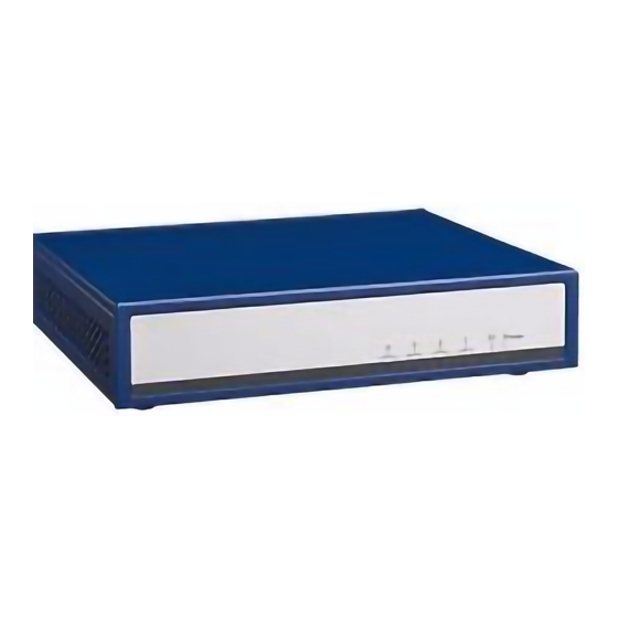
FWA-1330B
Tabletop Network Application Platform X86-Based
Intel® Bay Trail Processor
Startup Manual
Packing List
Before installation, ensure that the following materials have
been received:
• One FWA-1330B Internet Security Platform
• One box of accessories
• One warranty certificate
If any of these items are missing or damaged, please con-
tact your distributor or sales representative immediately.
Note:
Acrobat Reader may be used to view any PDF
file on the CD. Acrobat Reader can be down-
loaded at: www.adobe.com/Prodindex/acrobat/
readstep.html (Acrobat is a trademark of Adobe).
FWA-1330B Internet Security Platform
Front View
Back View
For more information on this and other Advantech
products, please visit our website at:
http://www.advantech.com
http://www.advantech.com/eplatform
For technical support and service, please visit our
support website at:
http://www.advantech.com/support
This manual is for the FWA-1330 series.
Part No. 2002A13320
Printed in Taiwan
1st Edition,
September, 2015
Specifications
• CPU: Intel® Celeron® Processor N2807
• Chipset: Intel Bay Trail SoC
• BIOS: AMI 16 Mbit SPI
• Memory: Single channel DDR3L 1333/1600 MHz SO-
DIMM, up to 4 GB
• Network Connectivity:
- Ethernet: 4 x Intel I211-AT 10/100/1000 Base-T Ethernet
- LAN Bypass: Up to 2 Segments
• Mass Storage:
- mSATA: 1 x mSATA slot (Half Size or Full Size)
- SATA: 1 x SATA connector, Support one 2.5" HDD bay
• Peripherals:
- Console:1x Console port (RJ45 connector)
- USB:2 x USB2.0 Type A connector
- VGA:1 x VGA Port on rear panel
- Mini PCIE: 1 x Mini PCIE slot (Half Size, USB Interface
Default, PCIE Interface Option)
- Pin Header: PS/2, GPIO, Reset, COM
• Front LED Indicator:
- Power LED:1 (Green)
- SATA LED:1 (Amber)
- LAN LED: 4 pairs (Speed and Status)
• Power supply: Adapter 40 W 12 V
• Dimensions (W x H x D):
208 x 44 x 181 mm (8.19" x 1.73" x 7.13")
• Weight:1.8 KG (3.96 lb)
• Environment: Operating
• Temperature: 0 ~ 40° C
(32 ~ 104° F)
• Humidity: 5 ~ 85% @ 40° C 5 ~ 95% @ 40° C
FWA-1330B Startup Manual 1
Non-operating
-20 ~ 75° C
(-4 ~ 167° F)
Advertisement
Table of Contents

Related Manuals for Advantech FWA-1330B


Summary of Contents for Advantech FWA-1330B
- Page 1 -20 ~ 75° C (32 ~ 104° F) (-4 ~ 167° F) • Humidity: 5 ~ 85% @ 40° C 5 ~ 95% @ 40° C For more information on this and other Advantech products, please visit our website at: http://www.advantech.com http://www.advantech.com/eplatform...
-
Page 2: Installation
(the third figure below shows the position of the card hooks). 3. Take one Nylok screw from the accessory box and insert it into the position marked by a red circle in the below figure to fix mSATA. 2 FWA-1330B Startup Manual... -
Page 3: Installing The Hdd Module
4. Here, FWA-1330 can support both Full Size and Half Size mSATA. If Full Size is required, please firstly Installing the HDD Module remove one copper cylinder shown in the below figure 1. Unfasten the four screws of the top cover for future use and fix mSATA. Please refer to the third figure below for and remove HDD bracket. an appropriate installation. Full Size Half Size FWA-1330B Startup Manual 3... - Page 4 B. Thermal pad should not be placed onto the HDD motor. 3. Take an HDD and insert it into the SATA interface as follow. 4. Use four sunk screws in the accessory box to fix the HDD module onto the bracket. 4 FWA-1330B Startup Manual...
-
Page 5: Install The Top Cover
1. Replace and fix the top cover with the four screws removed earlier. 7. Connect SATA cable and power cable of the HDD to the main board. Please follow the second figure to cor- rectly connect the cable. FWA-1330B Startup Manual 5... -
Page 6: Jumpers And Connectors
GPIO Connector GPIO5 PWR_BTN1 Power Button Signal Connector GPIO2 SMB_CN1 SMBus connector GPIO6 SYS_RST1 System Reset GPIO3 SATA_PWR_ Pin Header for GPIO7 LED1 SATA LED/Power LED JCMOS1 Pins Function Normal status Clear CMOS Default setting:1-2 Jumper Short 6 FWA-1330B Startup Manual... -
Page 7: Software Installations
4. For pluggable equipment, the power outlet shall be installed near the equipment and shall be easily accessible. 5. Keep this equipment away from humidity. 6. Put this equipment on a reliable surface during installation. Dropping it or letting it fall could cause damage. FWA-1330B Startup Manual 7... - Page 8 E) Reliable Earthing-Reliable earthing of rack-mounted equipment should be maintained. Particular attention should be given to supply connections other than direct connections to the branch circuit (e.g. use of power strips).” 8 FWA-1330B Startup Manual...
Need help?
Do you have a question about the FWA-1330B and is the answer not in the manual?
Questions and answers