Table of Contents
Advertisement
DKG-309 User Manual
DKG-309 AUTOMATIC MAINS FAILURE UNIT
Automatic mains failure
Engine control
Generator protection
Built in alarms and warning
Manual control enabled
J1939 engine monitoring and control port
J1939 ECU warnings displayed as text
Dual genset mutual standby operation
Load shedding, dummy load
Gas engine support
Engine idle speed control
3 phase mains voltage inputs
3 phase genset voltage inputs
3 phase genset CT inputs
Engine oil pressure measurement
Engine coolant temperature measurement
Fuel level measurement
Genset active power measurement
Genset power factor measurement
Engine rpm display
Periodic maintenance request indicator
Daily / weekly / monthly exerciser
Engine hours counter
Event logging with date-time stamp and complete
measurement values
Stores last 250 events
Statistical counters
Battery backed-up real time clock
Weekly operation schedule programs
Programmable parameters
FEATURES
All parameters field adjustable
Return to factory settings enabled
RS-232 serial port
Firmware downloadable from serial port
Free MS-Windows Remote monitoring SW:
-local and modem connection
-monitoring, download of parameters
-networking via modems
GSM and PSTN modem support
GSM-SMS sending in case of alarm
Modem call in case of alarm
MODBUS communication
128x64 blue graphic LCD display
Triple language support
Customer logo display capability
Configurable analogue inputs: 3
Configurable digital inputs: 8
Configurable relay outputs: 2
Total relay outputs: 6
Output expansion capability
Remote Start operation available
Mains simulation input
Engine Idle speed control
Internal buzzer for audible warning
Survives cranking dropouts
Sealed front panel
Plug-in connection system for easy replacement
Small dimensions (165x125x48mm)
Low cost
V-02
Tel: +90-216-466 84 60
Fax: +90-216 364 65 65
datakom@datakom.com.tr
http://www.datakom.com.tr
(11.05.2009)
Advertisement
Table of Contents

Related Manuals for Datakom DKG-309


Summary of Contents for Datakom DKG-309
- Page 1 DKG-309 User Manual V-02 (11.05.2009) Tel: +90-216-466 84 60 Fax: +90-216 364 65 65 datakom@datakom.com.tr http://www.datakom.com.tr DKG-309 AUTOMATIC MAINS FAILURE UNIT FEATURES Automatic mains failure All parameters field adjustable Engine control Return to factory settings enabled Generator protection RS-232 serial port...
-
Page 2: Table Of Contents
DKG-309 User Manual V-02 (11.05.2009) TABLE OF CONTENTS Section 1. INSTALLATION 1.1. Introduction to the Control Panel 1.2. Mounting the Unit 1.3. Wiring the Unit 2. INPUTS AND OUTPUTS 3. DISPLAYS 3.1. Led Displays 3.2. Language Selection 3.3. Digital Displays 4. -
Page 3: Installation
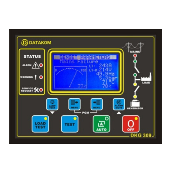
DKG-309 User Manual V-02 (11.05.2009) 1. INSTALLATION 1.1 Introduction to the Control Panel The unit is a control and protection panel used in gensets. It shows the measured values on its displays. The unit is designed to provide user friendliness for both the installer and the user. -
Page 4: Mounting The Unit
DKG-309 User Manual V-02 (11.05.2009) 1.2 Mounting the Unit The unit is designed for panel mounting. The user should not be able to access parts of the The unit is designed for panel mounting. The user should not be able to access parts of the The unit is designed for panel mounting. -
Page 5: Inputs And Outputs
DKG-309 User Manual V-02 (11.05.2009) 2. INPUTS AND OUTPUTS RS-232 SERIAL PORT: This connector provides serial data input and output for various purposes like remote monitoring and remote programming. EXTENSION CONNECTOR: This connector is intended for the connection to output extension modules. - Page 6 DKG-309 User Manual V-02 (11.05.2009) Term Function Technical data Description CHARGE Input and output Connect the charge alternator’s D+ terminal to this terminal. This terminal will supply the excitation current and measure the voltage of the charge alternator. RELAY-2 (HORN RELAY)
-
Page 7: Displays
DKG-309 User Manual V-02 (11.05.2009) 3. DISPLAYS 3.1 Led Displays The unit has 12 LEDs, divided in 3 groups: -Group_1: Operating mode: This group indicates the genset function. -Group_2: Mimic diagram: This group indicates the current status of the mains and genset voltages and contactors. -
Page 8: Language Selection
DKG-309 User Manual V-02 (11.05.2009) 3.2 Language Selection The unit is able to display information in 3 languages. Language selection is made through program parameter CONTROLLER CONFIGURATION > LANGUAGE SELECTION. Below selections are available: 0: English language 1: Turkish language... - Page 9 DKG-309 User Manual V-02 (11.05.2009) Screen Description Contents Mains parameters Genset status (phase to neutral) Mains Volts L1, Mains Frequency Mains Volts L2 , Battery Voltage Mains Volts L3, Coolant Temperature Mains parameters Genset status (phase to phase) Mains Volts L1-L2,...
- Page 10 DKG-309 User Manual V-02 (11.05.2009) Screen Description Contents Company Logo Alarm List If no alarm exists, ‘END OF ALARM LIST’ will be displayed. Existing alarms, load_dumps, warnings will be displayed as one screen for each entry. Switching to the next entry will be ▼...
-
Page 11: Alarms And Warnings
DKG-309 User Manual V-02 (11.05.2009) 4. ALARMS AND WARNINGS Alarms indicate an abnormal situation in the generating set are divided into 3 priority levels: 1- ALARMS: These are the most important fault conditions and cause: The related alarm led to be on steadily,... - Page 12 DKG-309 User Manual V-02 (11.05.2009) LOW FREQUENCY / HIGH FREQUENCY: Set if the generator frequency is outside programmed limits. These faults will be monitored with Holdoff Timer delay after the engine is running. Low and high limits for warning and alarm are separately programmable.
-
Page 13: Modes Of Operation
DKG-309 User Manual V-02 (11.05.2009) 5. MODES OF OPERATION The modes of operation are selected by pushing the front panel keys. Changing the operation mode while the genset is running will result into a behavior suitable for the new operating mode. For example, if the LOAD TEST mode is selected when genset is running at TEST mode, then the genset will take the load. -
Page 14: Sender Type Selection
DKG-309 User Manual V-02 (11.05.2009) 6.2 Sender type Selection The unit has the ability to adapt to any type of oil pressure and temperature senders. The commonly used standard sender characteristics are recorded in memory and selectable from a list. -
Page 15: Engine Idle Speed Operation
DKG-309 User Manual V-02 (11.05.2009) 6.4 Engine Idle Speed Operation It may be required that the engine runs at the idle speed for a programmed duration for engine heating. The idle operation duration is adjusted with the parameter Idle Speed Timer. The idle speed will be set by the governor control unit of the engine. -
Page 16: Mains Simulation
DKG-309 User Manual V-02 (11.05.2009) 6.7 Mains Simulation The unit offers an optional an optional SIMULATE MAINS signal input. If the program parameter . If the program parameter Simulate Mains Operation is set to is set to 1 then the SPARE_2 (37) input will be used for mains simulation. - Page 17 6.7 for a detailed explanation of this feature for a detailed explanation of this feature. Please contact DATAKOM for a complete application manual. Please contact DATAKOM for a complete application manual. Please contact DATAKOM for a complete application manual.
-
Page 18: Service Request Display
DKG-309 User Manual V-02 (11.05.2009) 6.10 Service Request Display Service Request Display This led is designed to help the periodic maintenance of the genset to be made consistently. This led is designed to help the periodic maintenance of the genset to be made consistently. -
Page 19: Modem Connection
If SMS message sending is enabled, then only the first telephone number will be used for modem calls. Advised modems are DATAKOM types which are powered up from the same DC battery Advised modems are DATAKOM types which are powered up from the same DC battery Advised modems are DATAKOM types which are powered up from the same DC battery voltage than the unit. -
Page 20: Sms Message Sending
GSM SMS messages. Any new upcoming alarm will result in a new GSM SMS message. The new message will indicate all existing alarms, even masked ones. The necessary GSM modem cable will be supplied by DATAKOM. This is the same cable as PSTN (land) modems. -
Page 21: Resuming To Factory Set Parameters
DKG-309 User Manual V-02 (11.05.2009) 6.17 Exerciser The unit offers automatic exerciser operation. The exercise operation may be done on a daily, automatic exerciser operation. The exercise operation may be done on a daily, automatic exerciser operation. The exercise operation may be done on a daily, weekly or monthly basis. -
Page 22: Gas Engine Fuel Solenoid Control
DKG-309 User Manual V-02 (11.05.2009) 6.19. Gas Engine Fuel Solenoid Control The unit provides a special function for the fuel solenoid control of a gas engine. The fuel solenoid of a gas engine is different from a diesel engine. It should be opened after the cranking has been started and should be closed between crank cycles. -
Page 23: Modbus Communication
Detailed description about the MODBUS protocol is found in the document “Modicon Modbus Protocol Reference Guide”. The web address is: www.modbus.org/docs/PI_MBUS_300.pdf Below is a limited shortlist of readable registers. For the detailed Modbus Application Manual and a complete list of registers please contact DATAKOM. ADDRESS DATA COEFFICIENT... -
Page 24: Weekly Operation Schedule
DKG-309 User Manual V-02 (11.05.2009) 9. WEEKLY OPERATION SCHEDULE In most applications, the genset is requested to operate only in working hours. Thanks to the weekly program feature unwanted operation of the genset may be prohibited. The unit has one programmable turn-on/turn-off time pairs for each day of week. These programmable parameters allow the genset to operate automatically only in allowed time limits. -
Page 25: Event Logging
DKG-309 User Manual V-02 (11.05.2009) 10. EVENT LOGGING The unit keeps record of the last keeps record of the last 100 events in order to supply information for the service personal. events in order to supply information for the service personal. -
Page 26: Statistical Counters
DKG-309 User Manual V-02 (11.05.2009) 11. STATISTICAL COUNTERS STATISTICAL COUNTERS The unit provides a set of non resettable incremental counters for statistical purposes. The unit provides a set of non resettable incremental counters for statistical purposes. The unit provides a set of non resettable incremental counters for statistical purposes. -
Page 27: Programming
DKG-309 User Manual V-02 (11.05.2009) 13. PROGRAMMING The program mode is used to program the timers, operational limits and the configuration of the unit. ◄ ► To enter the program mode, press together MENU and MENU buttons for 1 second. - Page 28 DKG-309 User Manual V-02 (11.05.2009) Program Group: Controller Configuration Parameter Definition Unit Factory Description This parameter is used to set LCD contrast. Adjust for LCD Contrast the best viewing angle. 0: English language selected. 1: Turkish language selected. This language may...
- Page 29 Simulate Mains signal disappears. Flashing Relay Timer hours Dual Genset Systems: flashing relay toggle timer. Please contact DATAKOM for dual genset mutual stanby operation. This parameter trims precisely the real time clock circuit. Values from 0 to 63 speed up the clock with Real Time Clock Adjust 0.25sec/day steps.
- Page 30 DKG-309 User Manual V-02 (11.05.2009) Parameter Definition Unit Factor Description y Set This parameter is used in the conversion of the genset frequency to engine rpm. RPM from genset frequency 0: read rpm from the optional MPU input 1: convert frequency to rpm (using crank teeth count)
- Page 31 DKG-309 User Manual V-02 (11.05.2009) Factory Parameter Definition Unit Description Low Battery Voltage If the battery voltage falls below this limit, this will Warning generate a LOW BATTERY warning. High Battery Voltage If the battery voltage goes over this limit, this will 31.0...
- Page 32 DKG-309 User Manual V-02 (11.05.2009) Program Group: Engine Parameters Factory Parameter Definition Unit Description If the genset frequency goes under this limit, a GENSET LOW FREQUENCY alarm is generated and the engine Low Frequency Shutdown stops. If the genset frequency goes under this limit, a GENSET Low Frequency Warning LOW FREQUENCY warning is generated.
- Page 33 DKG-309 User Manual V-02 (11.05.2009) Program Group: Engine Parameters (continued) Parameter Definition Unit Factory Description This is the maximum start period. Starting will be Crank Timer automatically cancelled if the genset fires before the timer. Wait Between Starts This is the waiting period between two start attempts.
- Page 34 DKG-309 User Manual V-02 (11.05.2009) Program Group: Adjust Date and Time Parameter Definition Unit Factory Description Date 01-31 Current day of the month. Month 01-12 Current month. Year 00-99 Last two digits of the current year. Hours 00-23 Current hour of the day.
- Page 35 DKG-309 User Manual V-02 (11.05.2009) Program Group: Sender Characteristics (continued) Parameter Definition Unit Factory Description Temperature Sender point 1, ohm value Temperature Sender Ohms - Temperature Sender point 1, ° C value Temperature Value -1 ° C Temperature Sender point 2, ohm value Temperature Sender Ohms - Temperature Sender point 2, °...
- Page 36 DKG-309 User Manual V-02 (11.05.2009) Program Group: Input Configuration (Low Oil Pressure Switch) Factory Parameter Definition Unit Description 0: Shutdown (the engine stops immediately) 1: Load Dump (the engine stops after cooldown) Action 2: Warning (the horn relay operates) 3: No operation...
- Page 37 DKG-309 User Manual V-02 (11.05.2009) Program Group: Input Configuration (Coolant Level Switch) Parameter Definition Unit Fac.Set Description 0: Shutdown (the engine stops immediately) 1: Load Dump (the engine stops after cooldown) Action 2: Warning (the horn relay operates) 3: No operation...
- Page 38 DKG-309 User Manual V-02 (11.05.2009) Program Group: Input Configuration (Spare–1 Input) Parameter Definition Unit Fac.Set Description 0: Shutdown (the engine stops immediately) 1: Load Dump (the engine stops after cooldown) Action 2: Warning (the horn relay operates) 3: No operation...
- Page 39 DKG-309 User Manual V-02 (11.05.2009) Program Group: Relay Definitions The parameters below define the functions of relay outputs. The unit has 6 relay outputs. The fixed function relays are Fuel, Start, Mains Contactor and Generator Contactor. RELAY-1 and RELAY- 2 have programmable functions, selected from a list.
- Page 40 DKG-309 User Manual V-02 (11.05.2009) The function of a programmable relay output may be selected from the below list. Fuel Oil switch alarm Oil switch warning Alarm Temp switch alarm Temp switch warn. Start Coolant Level switch Coolant Level switch...
- Page 41 DKG-309 User Manual V-02 (11.05.2009) Program Group: Site Id Parameter Definition Factory Set Description This is the site Id string sent at the beginning of an DATAKOM SITE SMS message for the identification of the genset Site Id String sending the SMS message. Any 20 character long string may be entered.
- Page 42 DKG-309 User Manual V-02 (11.05.2009) Program Group: Calibration Parameters These parameters adjust measurement calibration of the unit. Manual calibration is also allowed. During calibration, measurements to be calibrated are also visualized. Parameter Definition Unit Fac.Set Description Adjusts the measurement of mains voltage of phase...
-
Page 43: Troubleshooting
DKG-309 User Manual V-02 (11.05.2009) 14. TROUBLESHOOTING TROUBLESHOOTING The genset operates while AC mains are OK or continues to operate after AC mains are OK: The genset operates while AC mains are OK or continues to operate after AC mains are OK: The genset operates while AC mains are OK or continues to operate after AC mains are OK: -Check engine body grounding. - Page 44 DKG-309 User Manual V-02 (11.05.2009) When the AC mains fails, the engine starts to run but the unit gives START FAIL alarm and then the engine stops: -The generator phase voltages are not connected to the unit. Measure the AC voltage between terminals GEN L1-L2-L3 and Generator Neutral at the rear of the unit while the engine is running.
-
Page 45: Declaration Of Conformity
DKG-309 User Manual V-02 (11.05.2009) 15. DECLARATION OF CONFORMITY The unit conforms to the EU directives -2006/95/EC (low voltage) -2004/108/EC (electro-magnetic compatibility) Norms of reference: EN 61010 (safety requirements) EN 61326 (EMC requirements) The CE mark indicates that this product complies with the European requirements for safety, health environmental and customer protection. -
Page 46: Technical Specifications
DKG-309 User Manual V-02 (11.05.2009) 16. TECHNICAL SPECIFICATIONS Alternator voltage: 0 to 300 V-AC Phase to Neutral (0 to 520 V-AC Phase to Phase) Alternator frequency: 0-100 Hz. Mains voltage: 0 to 300 V-AC Phase to Neutral (0 to 520 V-AC Phase to Phase) Mains frequency: 0-100 Hz. -
Page 47: Connection Diagram
DKG-309 User Manual V-02 (11.05.2009) 15. CONNECTION DIAGRAM - 47 -... - Page 48 ERROR: stackunderflow OFFENDING COMMAND: ~ STACK:...
Need help?
Do you have a question about the DKG-309 and is the answer not in the manual?
Questions and answers