
Related Manuals for MOBA MCE Lasers DUO 2 v2


Summary of Contents for MOBA MCE Lasers DUO 2 v2
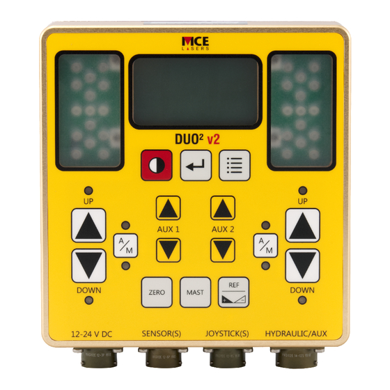
- Page 1 DUO 2 DUAL MACHINE CONTROL PANEL WITH AUXILIARY OUTPUT 5.16 DUO² AUX 1 AUX 2 DOWN DOWN ZERO MAST SENSOR(S) JOYSTICK(S) HYDRAULIC/AUX 12-24 V DC OPERATOR’S MANUAL...
- Page 2 Victoria, Australia Copyright © 2019 MOBA Australia MCE Lasers ® is a registered trademark of MOBA Australia. All rights reserved. No part of this manual may be reproduced in any form or by any means without prior written permission from the publishers.
- Page 3 WARRANTY STATEMENT OF LIMITED WARRANTY MOBA Australia warrants all equipment of its manufacture to be free of defects in material and workmanship for a period of twelve months. his warranty period is twelve months from the date of invoice. tems covered by this warranty are: sensors, transmitters, electronic levels, receivers, masts, control boxes, displays and accessories.
-
Page 4: Table Of Contents
TABLE OF CONTENTS 1. Product Overview ....................7 2. User Interface ....................8 2.1. Graphic Display ..................8 2.2. Key Functions ..................8 2.3. Key Legend .....................9 2.4. LED Indication ..................10 2.5. Sensor Lights ..................10 2.6. Configuration Menu ................11 3. First Steps .....................12 3.1. Basic Setup ...................12 3.2. - Page 5 TABLE OF CONTENTS (continued) 4.4 Reference, ffset & et arget .............32 4.4.1 To elect ef rence ..............33 4.4.2 To djust ef rence/ ffset ............33 4.4.3 To ransfer urrent ensor alue nto ef rence/ ffset ...33 4.4.4 To ero ef rence/ ffset value ..........34 5.
- Page 6 TABLE OF CONTENTS (continued) 5.5 Mast Mode of Operation ................46 5 5 . Mast Working Screen ..............46 . .1 5 5 . Mast Function Keys ..............46 . .2 5 5. . Adjusting Mast Position ..............47 5 5.4 Relative Offset ................48 5.5.4.1 Using the Panel Keys ............48 5.5.4.2 Using Optional Joystick ...........49 6 GNSS...
-
Page 7: Product Overview
PRODUCT OVERVIEW 5.16 AUX 1 AUX 2 DOWN DOWN ZERO MAST SENSOR(S) JOYSTICK(S) HYDRAULIC/AUX 12-24 V DC figure 1 The DUO is a control panel for dual machine control application. The DUO has a dual control for valve actuation and dual control for auxiliary valves. The system provides the user with the flexibility to independently use single or multiple valve control. -
Page 8: User Interface
USER INTERFACE 2.1 GRAPHIC DISPLAY The graphic display indicates the panel Laser Sensor Laser Sensor [mm] status, sensor reading and sensor dead band Ref = 012 accuracy setting. Menus, parameters, Laser +015 important information and various settings are displayed when menus are accessed. MAN AUTO figure 2 2.2 KEY FUNCTIONS... -
Page 9: Key Legend
KEY LEGEND: This manual uses key designator for each graphical key representation. Please refer to this section for graphical key equivalent of each key designator. CONTROL PANEL MINI JOYSTICK MODE = [POWER] key = [MENU] key LEFT A/M RIGHT A/M = [ENTER] key = [ZERO] key ZERO... -
Page 10: Led Indication
LED INDICATION AUTO LEDS: ON when hydraulics control for the side is in automatic mode. MANUAL LEDS: ON when hydraulics control for the side is in manual mode. UP/DOWN LEDS: ON when hydraulic valve for the side is activated up or down. DOWN 5 SENSOR LIGHTS... -
Page 11: Configuration Menu
LOW BATTERY WARNING If the battery voltage drops below the level required operat the unit, a low battery symbol will appear on the LCD briefly before the unit automatically shuts down. figure 5 CONFIGURATION MENU A variety of settings and features can be set or adjusted through the DUO2 configuration menu. -
Page 12: First Steps
FIRST STEPS This chapter will provide you with information n connecti and setting up DUO2 . In addition a description of the symbols and displays used in the working window will be explained. 3.1 BASIC SETUP The DUO control panel can be setup in multiple different configurations as illustrated below. -
Page 13: Cable Connections
DUO using A.R.S.080 cable. The end of the cable with the bare wires should be connected to the valves as explained in the following section. Note that the hydraulic valves are normally part of the machine and are not supplied by the MOBA Australia. -
Page 14: Hydraulic Alve Onfiguration
3.4 HYDRAULIC VALVES CONFIGURATION The CB.D2.CAN can manually and automatically drive most of the commercially available solenoid valves, including popular brands such as Danfoss, Eaton- Vickers, Rexroth and others. It has four different types of hydraulic output drive signal available, suitable for different types of valves as explained in the table below. - Page 15 The CB.D2.CAN is normally supplied with hydraulic cable A.RS.080 which has colour-coded and labelled bare wires on one end allowing the user to connect their valve according to the particular hydraulic output type requirement for that valve. Below are examples of how to connect the bare wires for each of the four hydraulic output types using as examples some common valve brands and assuming Hirschmann type connector (CETOP valves).
- Page 16 Hydraulic Output Example Valves Valve Pin Layout* Connections of A.RS.080 Type Bare Wires (Wire Colour - Wire Label) PIN 1: Grey – VCC Voltage Danfoss PVG series PIN 2: Yellow – SIG1/UP1 Proportional with PVE actuator PIN 3: Not Connected (V[O]) GND: Pink - GND Up Coil...
- Page 17 The CB.D2.CAN can optionally drive an additional On/Off type valve which can be used for auxiliary functions such as, for example, moving a wheel up and down on a skid steer machine. This hydraulic output can normally only be activated manually using the Aux Up and Down buttons. In special cases, when selected through the Advanced Settings in the menu, the Aux Up can be activated automatically whenever the main hydraulic output (up or down) is activated.
-
Page 18: Powering P U
3.5 POWERING UP Before powering up the DUO for the first time, a visual inspection is recommended to confirm everything is connected correctly and is well secured (refer top sections 3.1 - 3.4). Check and confirm especially that the type of hydraulic valves has been correctly determined and the wiring has been done as per section 3.4 for the particular type of valves. -
Page 19: Setting P Ydraulics U H
3.7 SETTING UP THE HYDRAULICS As the DUO supports multiple types of hydraulic Left Side valves it is very important to firstly select the Right Side Accessory Se nsor correct type of valve operating on the machine. LCD/LED Settings Advanced Settings From the Working screen press the [MENU] Exit... -
Page 20: Selecting Ype Of Ydraulics
Calibration On/Off (Low Side) Advance Settings On/Off (High Side) Copy to Right MOBA Gateway Exit Exit The DUO supports the following commercially available hydraulics valve types. 1. Proportional (VO) - Voltage controlled proportional hydraulics 2. Proportional (IO) - Current controlled proportional hydraulics 3. -
Page 21: Adjusting Ettings For Ydraulic Response
3.7.2 ADJUSTING SETTINGS FOR HYDRAULICS RESPONSE Using [AUX2] key select General Settings for hydraulics then press the ‘ ’ [ENTER] Hydraulic - Left (IO) General Settings Type [IO] Min Up 10.0% General Settings Min Down 10.0% Calibration Max Up = 100.0% figure 14 Advance Settings Max Down... -
Page 22: General Settings For Vo Hydraulics
3.7.2.1 GENERAL SETTINGS - VO HYDRAULICS 1. Min up: Minimum signal that is applied to move the blade or bucket in upward direction (VO) General Settings This signal is applied when the signal from the Min Up 10.0% connected sensor is just the ‘ON TARGET’... -
Page 23: General Settings For Io Hydraulics
3.7.2.2 GENERAL SETTINGS - IO HYDRAULICS 1. Min up: Minimum signal that is applied to (IO) General Settings move the blade or bucket in upward Min Up 10.0% Min Down 10.0% direction . This signal is applied when the Max Up = 100.0% signal from the connected sensor is just Max Down... -
Page 24: General Settings For On/Off Hydraulics
3.7.2.3 GENERAL SETTINGS - ON/OFF HYDRAULICS The On/Off hydraulic output can be made to pulse or to be solid. figure 17 On/Off (Low) Settings F-Sampling 4.0% Min Pulse Up 50ms 1. F-Sampling: frequency of the pulsing hydraulic Min Pulse Dn 50ms signal. -
Page 25: Calibration - Ydraulics
3.7.3 CALIBRATION - HYDRAULICS The Minimum and Maximum hydraulic signal settings can be determined by selecting the option in the hydraulics menu. In Hydraulics calibration menu using [AUX2] key select ‘Calibration’, then press [ENTER]. Hydraulic - Left Calibration - Left Type [VO] Min Test General Settings... -
Page 26: Min Pulse Calibration (H Ydraulics )
3.7.3.1 PULSE CALIBRATION HYDRAULICS The minimum settings required to move the blade or bucket up or down can be determined by selecting the ‘Min Test’ option. In this test mode the system automatically applies an up and down pulse alternately, allowing the user to see in real time the effect on the blade movement with each change in value for minimum up and minimum down settings. -
Page 27: Max Pulse Calibration Hydraulics
3.7.3.2 PULSE CALIBRATION HYDRAULICS maximum settings required to move the blade or bucket up or down can be determined by selecting the Max test option . In this test mode the system automatically applies an up and down pulse alternately, allowing the user to see in real time the effect on blade or bucket... -
Page 28: Advanced Ettings Ydraulics )
Exit The Advanced ettings for hydraulics can be used in special cases where ‘ ’ hydraulic response remain unsatisfactory after careful adjustment of the General hydraulic settings. Currently these settings are only available to MOBA Australia service technicians and distributors... -
Page 29: Working With Anel P
4. WORKING WITH PANEL Please refer to section 2.2 for Key Functions and Key Designators AUX 1 AUX 2 DOWN DOWN ZERO MAST figure 23 4.1 MANUALLY MOVING THE BLADE From the panel the left side up key can be used to manually activate the valves to move the left side of the blade up. -
Page 30: Setting The Alve Ontrol V C M Ode
4.2 SETTING VALVE CONTROL MODE From the panel use the [A/M] key to switch between the two modes of control for the hydraulics valves. Laser Sensor Laser Sensor [mm] Ref = 012 Laser figure 24 +015 MAN AUTO MANUAL MODE When the unit is in manual mode the panel LED MAN will be and the will appear on the screen, as shown in the picture below for left side. -
Page 31: Grade To Zero Operation
GRADE TO ZERO OPERATION The current screen reading for certain models of laser sensor, for GPS sensor and for masts can be zeroed at any time. From the working screen press the [ZERO] key to bring up the side selection screen for zeroing. -
Page 32: Reference, Ffset & Et Arget
REFERENCE, OFFSET & SET TARGET During normal operation, the currently used reference/set target value is displayed in the second line of the screen for all sensor types. This value is the desired offset of the blade or bucket from zero position. Laser sensors allow one reference /offset value only. -
Page 33: To Elect Ef Rence R E
4.4.1 TO SELECT THE REFERENCE From the Ref menu screen, use [AUX2] key to highlight the reference/offset, then press the [MENU] key to select the Reference/offset. The screen will return back to the working screen and the selected Ref will be shown on the second line of the screen. -
Page 34: To Ero Ef Rence/ Ffset Value R E
4.4.4 TO ZERO REFERENCE/OFFSET VALUE [AUX2] key to highlight the reference, then press [ENTER] key to edit the value . Press the [AUX2] Up and D n keys together to zero the Ref value. Press up and down keys together to zero Ref value. -
Page 35: Auxiliary Control
4.6 AUXILIARY CONTROL In addition to the left and right side hydraulic control, the DUO2 has the ability to control two auxiliary On/Off type valves which can be used for user defined applications such as smudge bar control. These can only be operated manually using [AUX1] [AUX2] U D... -
Page 36: Sensor Settings
5. SENSOR SETTINGS In either ‘Left Side’ or ‘Right Side’ settings menu, u sing [AUX2] ke scroll down to select the Sensor Settings then press ‘ ’ [ENTER] key to bring ‘S ensor etting . ’ Based on the sensor connected the settings could differ. SLOPE SENSOR SETTINGS Slope Sensor [Left]... -
Page 37: General Sensor Settings
5.1 GENERAL SENSOR SETTINGS 5.1.1 RESPONSE ADJUSTMENT When enabled, response lets you select between 90 predefined setting combinations of deadband and proportional range which directly affect overall response of the system. Response of 1.0 applies the slowest and most accurate response possible Response of 10.0 applies the fastest and least accurate... -
Page 38: Dead Band Adjustments
5.1.2 DEAD BAND ADJUSTMENTS This defines the accuracy of the system. The bigger the deadband, the less accurate the system is but the easier it is to achieve fast and stable hydraulic response Conversely, the smaller the deadband the more accurate the system is but the harder it is to achieve fast and stable hydraulic response. -
Page 39: Proportional Range Djustment A
5.1.3 PROPORTIONAL RANGE ADJUSTMENT The Proportional Range is the range of the sensor reading above and below the target over which the hydraulic output signal varies proportionally to the deviation of the sensor reading from the target. The Min hydraulic output is applied when the sensor reading is just outside the deadband (beginning of the Proportional range) and the Max hydraulic out put is reached when the sensor reading deviates from the Target by by an amount equal to or greater than the selected Proportional range. -
Page 40: Measurement Mode
5.1.5 MEASUREMENT MODE The measurement mode for sensors with ability to zero the reading can switch between Relative [REL] and Absolute [ABS]. Relative mode means that the sensor reading is relative to the position where the zeroing occurred. Absolute mode means the sensor reading is taken from the factory default ero position for example, for laser sensors this is the physical centre of the receiving area. -
Page 41: Calibrati Ng Slope & Race Sensors
CALIBRATI SLOPE & TRACE SENSORS 5.2.1 BEFORE CALIBRATING SLOPE SENSOR Using the slope sensor for the first time or after remounting, it is important that it is mounted and calibrated correctly. The mounting should be robust enough to guarantee that the sensor will not move while the blade is being used. Preferably the sensor should not be removed once mounted so as to avoid having to repeat the calibration procedure. - Page 42 The operating range of the trace sensor is maximum 450 mm and minimum 250 mm and during normal grading operations, it is recommended that the sensor is at a distance from the tracked surface roughly midway between the maximum and minimum , ie;...
-
Page 43: Slope Sensor - Side Selection
5.3 SLOPE SENSOR - SIDE SELECTION When one side is controlling the slope of the blade and the other side is controlling the height of the blade , the levelling of the two sides can be done by adjust ing one side at the time , rather than both sides at once. -
Page 44: 2. 4 Backlight Off/On/Auto Settings
5.4.2 BACK LIGHT OFF/ N AUTO SETTING With the Light O O A ff/ n/ uto option highlighted press [ENTER] key to select one of three power options for the backlight. The selected setting is shown enclosed in [ ]. The three settings work as below : 1. -
Page 45: 5 Reverse Lcd
5.4.5 REVERSE LCD [AUX2] key to highlight the ‘ Reverse LCD ’ setting and then press [ENTER] to reverse the default LCD colour settings LCD Backlight LCD Backlight LCD Contrast LCD Contrast Reverse LCD Reverse LCD LED Brightness LED Brightness figure 46 Exit Exit... -
Page 46: Mast Mode Of Operation
5.5 MAST MODE OF OPERATION 5.5.1 MAST WORKING SCREEN From the main working screen, press [MAST] key to display the mast working screen he image below shows the current position of the mast in millimeters. In case mast is connected on either side of the DUO a message saying “No MAST”... - Page 47 5.5.3 ADJUSTING MAST POSITION Basic mast position adjustment is don with [AUX2] key. ressing [ZERO] will set the current mast position to zero. The reference menu allows to program and memorise 4 positions for quick use in quick position change. To access the reference menu press...
-
Page 48: 5 5.4 Relative Offset
5.5.4 RELATIVE OFFSET 5.5.4.1 USING THE PANEL KEYS The mast can be adjusted to an offset value that is setup in the mast reference offset (RO1 and R 2).To set the offset value 1) P ress the [REF] button from the mast working screen 2) S croll... -
Page 49: Using Optional Joystick
5.5.4.2 USING OPTIONAL JOYSTICK n optional joystick can also be used to adjust the mast height by relative offset RO1 and R 2. Follow the steps below to take advantage of this feature. Note: Relative Offset RO1 and RO2 must be set to zero for this function to work. - Page 50 Increase RO1 figure 53 MODE UP LEFT Increase RO2 LEFT A/M Decrease RO1 DOWN RIGHT RIGHT A/M Decrease RO2 GLAND Tilt ‘DOWN LEFT’ Tilt ‘UP RIGHT’ to decrease RO1 offset to increase RO2 offset T increase the mast height by RO1 offset, press and hold [L/R] button then tilt the joystick towards ‘UP LEFT’...
-
Page 51: Gnss Sensor
6. GN S S SENSOR GNSS sensor enables user to perform land leve ling and grading over large area with slightly less accuracy than levelling lasers. It can be used in junction with or as a replacement of level lasers. It supports several Job types, namely Flat Job, Single Slope Job and Dual Slope Job. -
Page 52: Gnss Job Type Selection And Setup
6.3 GN S JOB TYPE SELECTION & SETUP Press [ENTER] key to bring up the job selection menu. Select the job type and follow nstructions to setup the job direction. Job Type [Slope] Flat Job? Job Target Settings Slope Job Exit Dual Slope Job figure 55... -
Page 53: Gnss Auto Mode
6. GN SS AUTO MODE To enable GNSS Auto Mode, a Dual Slope Job has to be created and the Target Slopes have to be set beforehand. Please refer to Section 6.3 for instructions. MAKING AVAILABLE GNSS AUTOMATIC MODE By default, GNSS automatic mode is disabled and not available from the panel. To make this option available, use [AUX2] key t scroll down to Advanced... -
Page 54: Reset To System Default
7. RESET TO SYSTEM DEFAULT From the main menu screen use [AUX2] key to select he ‘ Set Default option ’ then press [ENTER] key reset all the settings to factory default Left Side Are you sure to Right Side restore Default? Slope Side = [Right] LCD/LED Settings... -
Page 55: Joystick Type
8. JOYSTICK TYPE (optional) DUO supports multiple types of joysticks, so it is very important to select the right type of joystick connected to the system. From the main menu screen use [AUX2] key to scroll down to joystick option keep press ing the... - Page 56 (b) Side Mini & Aux Stick - as above with an additional auxiliary hydraulic activation function. This additional auxiliary hydraulic is activated by pressing the L/R button. (c) Proportional Mini Stick - (i) hydraulic up and down activations for a given side are located on the same axis on the joystick handle.
- Page 57 Auto/Man tick this joystick uses a toggle switch rather than a handle for hydraulic activation and another toggle switch for Auto/Manual selection. ‘ ’ Available only for left side. figure 65 UP/DOWN AUTO/MANUAL SWITCH SWITCH Note: With this option , the [A/M] key on the control panel will not work in the manner described in section 4.2 because the connected joystick will override this...
-
Page 58: Practical Example
PRACTICAL EXAMPLE The following example is provided to help demonstrate how setting reference offsets, zeroing and mounting would be done in practice. This example involves a race sensor. Assume the grading requirement is to maintain a relative distance of -50 mm between the cutting edge of the blade and the top of the curb as shown in igure below. - Page 59 OPTION 2: 1. Position the cutting edge of the blade to be level with the top of the curb and the ultrasonic sensor to be above the curb as shown in the illustrations below. The ultrasonic sensor should be approximately 380-420 mm above the curb that is, 50 mm above the desired sensor range of 330-370 mm during normal grading operations.
- Page 60 A U S T R A L I A P T Y L T D MOBA MOBILE AUTOMATION AUSTRALIA PTY LTD ABN - 866 279 713 68 90 Willandra Drive, Epping, Victoria, Australia 3076 Ph: +61 3 9357 0055 Email: aumoba@moba.de www.moba-automation.com.au...
Need help?
Do you have a question about the MCE Lasers DUO 2 v2 and is the answer not in the manual?
Questions and answers