Table of Contents
Advertisement
Quick Links
Advertisement
Table of Contents

Related Manuals for ZUCCHETTI AZZURRO ZCS

Summary of Contents for ZUCCHETTI AZZURRO ZCS
- Page 1 EV CHARGER 3PH 22KW...
- Page 2 Main Document Only. EV CHARGER 3PH 22kW User Manual Manual of 03/05/2021 Rev. 1.1 “User Manual EV CHARGER 3PH 22kW” 1/62...
- Page 3 Copyright statement Copyright of this manual belongs to Zucchetti Centro Sistemi S.p.A. No part of this manual may be copied (including the software), reproduced or distributed in any form or by any means without the permission of Zucchetti Centro Sistemi S.p.A.
-
Page 4: Table Of Contents
Main Document Only. Table of Contents Preliminary safety instructions ......................8 1.1. Safety instructions ........................8 1.2. Symbols and icons ........................11 1.3. Labels............................12 Product features ..........................13 2.1. Product presentation ....................... 13 2.2. Operating diagram ........................14 Installation ............................16 3.1. - Page 5 Main Document Only. 7.2. Password setting, mode of use and power limitation ............... 33 7.3. Menu for repairs or maintenance .................... 35 7.4. Configuration of RFID card (to enable charging in online and offline mode) ......36 Working mode ..........................38 8.1.
- Page 6 Main Document Only. 12.2. Maintenance ..........................60 Dismantling and disposal ......................61 Warranty ............................. 62 Manual of 03/05/2021 Rev. 1.1 “User Manual EV CHARGER 3PH 22kW” 5/62...
- Page 7 Main Document Only. Preface General information Please read this manual carefully before installation, use or maintenance. This manual contains important safety instructions that must be followed during installation and maintenance of the system. Scope This manual describes the assembly, installation, electrical connection, commissioning, maintenance and troubleshooting of the EV CHARGER: 3PH 22kW Keep this manual so that it is accessible at all times.
- Page 8 Main Document Only. Caution: indicates a hazardous situation which, if not resolved or avoided, could result in minor or moderate personal injury Caution Attention: indicates a potentially hazardous situation which, if not resolved or avoided, could result in damage to the system or other property Attention Note: provides important tips on the correct and optimal...
-
Page 9: Preliminary Safety Instructions
For safety reasons, this charging station can only be installed and serviced by a qualified electrician with the necessary training and/or skills and knowledge. Zucchetti Centro Sistemi S.p.A. declines all responsibility for damage to property or personal injury caused by incorrect use of the device. - Page 10 If necessary, request assistance from an installer or from Zucchetti Centro Sistemi S.p.A. Transport of the equipment, especially by road, must be carried out with vehicles suitable to protect the components (in particular, electronic components) against violent knocks, humidity, vibrations, etc.
- Page 11 Main Document Only. All installation operations must be carried out by a professional electrician, who has carefully read this manual and understands its contents! Warning Before connecting the charging station to the grid, make sure that all the necessary permits have been obtained from the local grid operator and that all the electrical connections have been completed by a professional electrician.
-
Page 12: Symbols And Icons
Main Document Only. Maintenance and repair Keep the charging station clean and dry; if you need to clean it, use a clean dry cloth. It is very dangerous to touch the inside of the charging station, therefore it is strictly forbidden to do so while the system is running. -
Page 13: Labels
Main Document Only. Read this manual before installing the charging station. Degree of protection of the equipment according to the IEC 70- 1 standard (EN 60529 June 1997). IP54 means that it is resistant against water and rust, therefore also suitable for outdoor operation and maintenance. Table 1 –... -
Page 14: Product Features
Main Document Only. 2. Product features 2.1. Product presentation The EV CHARGER 3PH 22kW series are electric vehicle battery chargers that can communicate with the Battery Management System (BMS) of vehicles and provide them with the power needed for charging, thus guaranteeing the protection of the electrical system. They do not convert the mains voltage or current but simply regulate the flow and have internal protection devices in case of short circuit or other types of battery faults. -
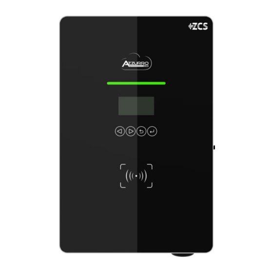
Page 15: Operating Diagram
Main Document Only. Figure 4 – Front and side view of the charging station 2.2. Operating diagram Figure 5– Operating diagram of the charging station The charging station connects to an electric vehicle via a Type2 connector (the cable is optional). According to the standards, the charging station is identified with Type3 (wall-box) in which the station is responsible for any power limitations, protections of various types and start-stop charging. - Page 16 Main Document Only. Figure 6 - Type2 Connector The station is equipped with a MID metering system that measures the energy supplied to the vehicle. The possible connection with an external communication gate also allows remote control of the station, invoicing of the energy and other functions. It is compatible with all types of cables and power sockets in order to ensure safe charging.
-
Page 17: Installation
Main Document Only. 3. Installation Figure 7 - Installation procedure DO NOT install the charging station near flammable materials. • DO NOT install the charging station in an area where flammable or • explosive materials are stored. Danger Take into account the weight of the charging station during •... - Page 18 Main Document Only. Checking the product After removing the charging station from its packaging, check that the product is intact and complete. If any damage is found or components are missing, contact the supplier and transport company. Contents of the packaging Part Charging station Screw with built-in washer...
-
Page 19: Installation Tools
Main Document Only. Wire ferrules Wall support Declaration of Conformity User Manual Warranty Table 2 – Package contents 3.1.1. Installation tools The following tools are required for the installation of the charging station and electrical connections; therefore, they must be prepared before installation. Manual of 03/05/2021 Rev. - Page 20 Main Document Only. Tool Function To screw and unscrew Screwdriver screws for the various connections To drill holes in the wall for Drill fixing To cut and tighten the cable Diagonal pliers ends Crimping tool To crimp the power cables To remove the outer sheath Wire stripping tool of the cables...
-
Page 21: Installation Process
Main Document Only. To make sure the bracket is Level level ESD gloves Protective clothing Safety goggles Protective clothing Table 3 – Installation tools 3.2. Installation process 3.2.1. Installation position Choose an appropriate installation location for the charging station. Follow the requirements below to determine the installation position. -
Page 22: Materials And Cables
Main Document Only. To prevent damage and personal injury, hold the device securely • when moving as it is a heavy piece of equipment Always position the device horizontally • Attention 3.3. Materials and cables First name Specifications Quantity Power cord ≥... -
Page 23: Electrical Connections
Before making any electrical connections, make sure there is no AC current. Zucchetti Centro Sistemi Spa assumes no responsibility for any liabilities arising from the use of this product. Installation must... - Page 24 Main Document Only. Figure 9 – Preparing the ground cable (1) 1) Insert the exposed wires into the OT terminal and crimp them using a crimping tool, as shown in relative Figure. Note 1: L3 is the length between the insulation layer of the ground cable and the crimped part. L4 is the distance between the crimped part and the conductor wires protruding from the crimped part.
-
Page 25: Connecting The Ac Power Cables
Main Document Only. Figure 11 - Connecting the ground terminal 4.2. Connecting the AC power cables Connect the station to the AC power supply network or power grid using AC power cables. Context The AC power cables used for the charging station must be three-pole outdoor cables. For easier installation, use flexible cables. - Page 26 Main Document Only. Figure 12 - Connecting the AC output cables (1) 2) Connect the AC power cable according to the following criteria: Connect the ground wire (yellow-green) to the hole labelled “PE”, and tighten the cable • using a screwdriver as described in the previous paragraph. Connect the line wires (brown, black, grey) to the holes labelled “L1, “L2, “L3”, and tighten •...
-
Page 27: External Protection Devices
Main Document Only. Do not reverse the “line” and “neutral” connections. The device will signal an error with the status bar flashing red. Attention 4.3. External protection devices The charging station is equipped with a Residual Current Device (RCD) to detect any current faults. It is also equipped with a detection system for DC components above 6mA. - Page 28 Main Document Only. Figure 14 - Communication system When grouping chargers together, for example, in public car parks, a single gate functions as an access gate for up to 12 chargers. The gate is connected to charger #1 and the other chargers are connected one by one via network cables between the various CAN ports (relative Figure).
-
Page 29: Mounting
Main Document Only. 5. Mounting 5.1. Wall mounting 1) Identify the installation position and mark the two holes for the wall screws, which will be inserted in the top rear of the charging station. You can use the hole jig found in the package. 2) Insert the plugs horizontally into the holes made, paying attention to the force and depth with which they are inserted (make sure the plug completely enters the hole). -
Page 30: Mounting On Metal Support
Main Document Only. 5.2. Mounting on metal support 1) Place the ground support in the centre of the parking area 2) Bury the connection cables, with at least 150 cm of the cables protruding above the surface 3) The communication and power cables run inside the support 4) Secure the station from below using the screws contained in the mounting kit. -
Page 31: Locking
Main Document Only. 5.3. Locking The locking of the charger housing does not depend on the type of mounting. Turn on the switch inside and close the front cover of the charger with the wrench supplied. The locks are located on the right side. LOCK Figure 18 –... -
Page 32: Commissioning
Main Document Only. 6. Commissioning 6.1. Preliminary safety inspection Make sure that the AC voltage falls within the range permitted by the device. Attention Check the following points before starting up the charging station: 1) Positioning: Check that the position is stable and solid and that the charging station does not move unintentionally. -
Page 33: Configuration
Main Document Only. 7. Configuration Configuration is necessary for the commissioning of the electric vehicle charging station; without it the charger may not work or may work incorrectly Note 7.1. Procedure 1) After installing the charging station properly (see sections 3, 4, 5 and 6, power it up and check that the display doesn't show any faults or errors, and that the LED line is not flashing green. -
Page 34: Password Setting, Mode Of Use And Power Limitation
Main Document Only. 1. Setting 2.Maintenance 3. Management Figure 22 - Main configuration screen 7.2. Password setting, mode of use and power limitation 1) From the screen shown in relative Figure, select point ‘1. Settings’ and press the Confirm/Enter key. Wait for the page shown in relative Figure to appear. Set PWD Set Mode Set Current... - Page 35 Main Document Only. Once the password has been changed, you will no longer be able to reset it. Losing the new password means losing access to the device for future configuration changes. Therefore, it is highly recommended not to change the password.
-
Page 36: Menu For Repairs Or Maintenance
Main Document Only. 10 A 16 A Current: 32A Figure 26 - Screen for setting the current limit 8) Select the desired current limit. The following power limits can be set: 32A corresponds to the maximum limit of 7kW for single-phase and 22kW for three-phase; •... -
Page 37: Configuration Of Rfid Card (To Enable Charging In Online And Offline Mode)
Main Document Only. 2 <yes> Select yes, restart in 5s 1 2 3 4 5 6 7 8 9 0 Figure 28 - Restart screen 3) Select 'Clear log' from the screen shown in relative Figure to clear the list of events on the device. - Page 38 Main Document Only. 2) To add a card for activating the charging, select ‘1. Add Card’ and wait for the screen shown in relative Figure to appear. Supports up to 8 cards Existing: x Swipe to add card Figure 31 - Add Card screen Swipe the card to be added on the device reader;...
-
Page 39: Working Mode
Main Document Only. 8. Working mode Refer to chapter 6 for configuring the various modes. 8.1. Online This operating mode is typical for large users with multiple battery chargers on the same network who need to manage charging authorisations, charging bookings, remote stops and starts, billing system, etc. -
Page 40: Offline
Main Document Only. Icon Description No connection to the portal - Plug & Play working mode and with Connext ENGATE connected correctly and not connected to the portal - check ENGATE configuration ENGATE connected correctly and connected to the portal Table 6 - Icons for connection to ENGATE 8.2. -
Page 41: Plug&Play
Main Document Only. Figure 35 - Offline mode For example, it can be used in a hotel or holiday farmhouse as a service offered to guests. Using RFID cards prevents generic charging of vehicles, but only allows holders of an enabling key to charge their vehicles. - Page 42 Main Document Only. Figure 36 - Plug&Play mode Manual of 03/05/2021 Rev. 1.1 “User Manual EV CHARGER 3PH 22kW” 41/62...
-
Page 43: Zvm-Gateway
Main Document Only. 9. ZVM-GATEWAY 9.1. Introduction EN-GATE is a control module for the online management of wallboxes. This user manual is a guide for the installation, commissioning and operation of the ZVM-GATEWAY system, and provides useful information on its technical installation and use. Before any operation, please read this document carefully to understand how the device works. -
Page 44: Features
Main Document Only. 9.3. Features 9.3.1. OCCP 1.6 Protocol The ZVM-GATEWAY system is connected to the chargers via a CAN communication input and via Ethernet port for communication with the Internet. Using the OCCP 1.6 communication protocol, the ZVM-GATEWAY reports the information of the charger to the backend in real time, as well as information of control operations such as reservations, and charging start and stop. - Page 45 Main Document Only. The length of the communication cable between the ZVM-GATEWAY and charger no. 1 should be less than 10 meters, and the maximum distance between the ZVM-GATEWAY and the last charger in the chain should be less than 100 meters. The balancing of the loads prevents overloading of one charger at the expense of the others;...
-
Page 46: Led Indications
Main Document Only. Figure 379 – Device dimensions 9.3.3. LED indications Reference LED Definition Green light flashing: ZVM-GATEWAY in operation Operating status (left) Green light steady/off: ZVM-GATEWAY not in operation Green light steady: ZVM-GATEWAY and Back-end connected Back-end connection (centre) Flashes once: back-end is communicating Off: connection between ZVM-GATEWAY and back-end failed Green light steady: Connection established... -
Page 47: Installation
Main Document Only. 9.4. Installation 9.4.1. Installation tips The CAN connection between the ZVM-GATEWAY and devices can also function as a power supply, and not only for sending data. The distance between the ZVM-GATEWAY and the chargers should be less than 10 meters, otherwise another 12-24V power supply unit is required as an additional external power supply. -
Page 48: Internet Connection
Main Document Only. Figure 380 - Dimensions for installation If the ZVM-GATEWAY is installed outdoors, extra protection is required to protect it from the weather. 9.4.4. Internet connection To connect the system to the internet, the Ethernet cable must be connected to the ETN port on the device; the network cable connected to Charger no. -
Page 49: Wi-Fi Configuration
Main Document Only. 2. The LED indicating lights on the chargers should be flashing green. If the chargers are not working properly, check the manual and, if necessary, contact the dealer. The “ADD” symbol should appear in the top right-hand corner of the charger display. 3. - Page 50 Main Document Only. Password: admin Manual of 03/05/2021 Rev. 1.1 “User Manual EV CHARGER 3PH 22kW” 49/62...
- Page 51 Main Document Only. 6. Click on “Search Wi-Fi”, select the available Wi-Fi network and enter the network password. Click “Confirm.” To connect to the device, you need to have a stable signal and know the password of the Wi-Fi network. Manual of 03/05/2021 Rev.
- Page 52 Main Document Only. 7. If the connection is successful, the gateway will restart automatically. 8. Wait until the 3 LEDs on the device are all lit up (steady or flashing LEDs), which means that the configuration is successful and the device is ready to communicate. Manual of 03/05/2021 Rev.
-
Page 53: Back-End Configuration
Main Document Only. 9.7. Back-end configuration The ZVM-GATEWAY communicates by default with the manufacturer's back-end. If communication with another back-end is necessary, the settings need to be changed. For further information, contact the dealer. 1. From the same initial status page, click “Set ENGATE.” Manual of 03/05/2021 Rev. - Page 54 Main Document Only. 2. When the screen opens, the manufacturer's credentials are present by default. They must be deleted: Server IP: eu.en-plus.con Server Port: 33033 3. Enter the credentials of Azzurro ZCS as follows: Server IP: evchargers.zcsazzurro.com Server Port: 33033 Click “Confirm.”...
- Page 55 Main Document Only. 5. Check that the Wi-Fi and Back-end settings have been saved in the “ENGATE INFO” screen. Manual of 03/05/2021 Rev. 1.1 “User Manual EV CHARGER 3PH 22kW” 54/62...
-
Page 56: Zvm-Gateway Update
Main Document Only. To configure a back-end other than Azzurro, such as public charging networks like EvWay, NextCharge, etc, complete the fields: Server IP Server Port Server Path according to the instructions, and wait for the device to restart. 9.8. ZVM-GATEWAY update If the device needs to be updated after consulting with technical support, request the necessary files and save them on a USB memory stick. -
Page 57: Operation
Main Document Only. 10. Operation 10.1. Connecting the charger to the electric vehicle Position the electric vehicle near the charger, making sure the cable is not taut. 1) Pull out the battery-charger cable from the electric vehicle and connect the charger and electric vehicle connectors. -
Page 58: Technical Datasheet
Main Document Only. 11. Technical datasheet Manual of 03/05/2021 Rev. 1.1 “User Manual EV CHARGER 3PH 22kW” 57/62... -
Page 59: Troubleshooting And Maintenance
Main Document Only. 12. Troubleshooting and maintenance 12.1. Troubleshooting This section contains information and procedures on how to troubleshoot any faults and errors that may occur during operation of the charging station. If you have any problems please follow these steps: 1) Check the warning messages and error codes on the information panel of the device. - Page 60 Main Document Only. 1. Check the input voltage from the back-end 4) Input The input voltage on the AC 2. If the voltage is below 140Vac for a limited undervoltage side may be too low period of time, wait for the grid to re- establish an adequate voltage value.
- Page 61 Main Document Only. Note: If the above problems cannot be resolved, contact your dealer. 12.2. Maintenance Charging stations generally do not require daily or periodic maintenance. Cleaning the charging station Use an air compressor, a soft dry cloth or soft-bristled brush to clean the charging station. Do not use water, corrosive chemical substances or aggressive detergents.
- Page 62 Main Document Only. 13. Dismantling and disposal The packaging materials are compatible with the environment and can be recycled. Therefore, they can be disposed of in special recycling containers in accordance with the local waste disposal regulations. However, the charger cannot be disposed of as household waste, but must be treated as special waste.
- Page 63 Main Document Only. 14. Warranty Zucchetti Centro Sistemi SpA provides a warranty of 2 years from the date of installation of the charging station, subject to registration on the website https://www.zcsazzurro.com/it/estensione-garanzia. During the warranty period, Zucchetti Centro Sistemi S.p.A. guarantees the normal operation of the charging station.
Need help?
Do you have a question about the AZZURRO ZCS and is the answer not in the manual?
Questions and answers