Advertisement
Quick Links
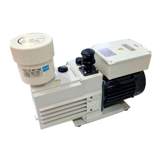
Oil Sealed Rotary Vacuum Pump
Please read this manual thoroughly to ensure safe and effective use of the equipment.
Keep this manual in a place where it can be referred to at any time and look after it
carefully.
The contents of this instruction manual are subject to change without prior notice due
to improvements in performance and the functions of the product.
Instruction Manual
For
Original Instructions
Model
GHD-031A
GHD-031B
Request to Users
ULVAC KIKO, Inc.
No.1000310-2-01-14
Advertisement

Related Manuals for Ulvac GHD-031A


Summary of Contents for Ulvac GHD-031A
- Page 1 Keep this manual in a place where it can be referred to at any time and look after it carefully. The contents of this instruction manual are subject to change without prior notice due to improvements in performance and the functions of the product. ULVAC KIKO, Inc.
-
Page 2: Table Of Contents
Contents 0.Introduction ・・・・・・・・・・01 0.1 Before using the vacuum pump ・・・・・・・・・・01 0.2 Safety symbols ・・・・・・・・・・03 1.For safe operation ・・・・・・・・・・ 1 1.1 Hazards peculiar to the pump and safety measures ・・・・・・・・・・ 1 Danger 1.1.1 Leakage of dangerous gas and material ・・・・・・・・・・ 1 Warning 1.1.2 Electric shock... - Page 3 4.Operation ・・・・・・・・・・16 4.1 Cautions for operation ・・・・・・・・・・16 4.2 Start of operation ・・・・・・・・・・16 4.3 Stopping the operation ・・・・・・・・・・17 4.4 Operation in cold climates ・・・・・・・・・・17 4.5 Thermal protector ・・・・・・・・・・17 4.6 Magnet coupling ・・・・・・・・・・18 4.7 Oil mist trap (Option) ・・・・・・・・・・18 4.8 Restriction on operation when the oil mist trap is installed ・・・・・・・・・・18 5.Pump performance ・・・・・・・・・・19 5.1 Ultimate pressure...
- Page 4 Figures and Tables Figure1. Dimensional drawing of GHD-031 oil sealed rotary vacuum pump・・・・・・・・・ 6 Figure2. Basic piping diagram to the vacuum chamber ・・・・・・・・・・10 Figure3. Electric wiring diagram ・・・・・・・・・・12 Figure4. Inlet (EN60320-1) ・・・・・・・・・・12 Figure5. Change region of the voltage and frequency ・・・・・・・・・・15 Figure6.
-
Page 5: Before Using The Vacuum Pump
0. Introduction Before using the vacuum pump Thank you for purchasing this product. Your custom is very much appreciated. This pump is only for vacuum pumping, and may malfunction or cause accidents if not handled appropriately. Please use instruction manuals after attention enough for check / maintenance / security sides after a reading well. - Page 6 Safety during repair When it is asked us for repair, please inform the use situation of having hazardous substance or not in particular for the safe management of the repair worker. The use situation declines repair in the case of lack of foresight. Confirmation at the time of the unpacking Although the pump is delivered with great care, check the following after unpacking.
-
Page 7: Safety Symbols
Safety symbols In this instruction manual and on warning labels attached to the pump, the following symbols are used so that matters which must be strictly adhered to can be readily understood. These symbols are divided as shown below. Danger When mishandled, there is an imminent danger of the operator suffering a fatal accident or serious injury. - Page 8 Electric shock Always switch off the main power supply before installing electrical wiring or performing any electrical work on the pump. Failure to do so may result in electric shock. The inlet port of the pump The outlet port of the pump Various label putting positional externals -04-...
- Page 9 Table for various labels Label name Label ① Rotation ② Burn caution ③ Electric shock caution ④ Installation caution ⑤ Transportation caution GHD-031A GHD-031B ⑥ Pump -05-...
- Page 10 Label name Label ⑦ Inlet ⑧ Position ⑨ High temperature caution ⑩ Outlet ⑪ Pump oil(R-2) ⑫ Passed ⑬ Warning explosion -06-...
-
Page 11: 1.For Safe Operation
1. For safe operation Hazards peculiar to the pump and safety measures Before operating or inspecting the pump, read this section carefully to fully understand potential hazards and prevention methods. The pump is not to be used with toxic of flammable gases. Danger 1.1.1 Leakage of dangerous gas and material... - Page 12 Warning Explosion 1.1.3 Cause Prevention method and measures Pump inside pressure rises, and the The maximum internal pump pressure is 0.03 level gauge of the pump ejects. MPa (gauge pressure). Measure the pressure at the outlet side and, if the pressure is 0.03 MPa or more (gauge pressure);...
- Page 13 1.1.4 Caution High temperature Cause Prevention method and measures High temperatures caused burns. ①The pump reaches a high temperature during operation. (Temperature increasing) Pump main unit during non-load operation →30K Motor during non-load operation →35K Pump main unit during high-load operation →35K Motor during high-load operation →40K...
-
Page 14: Safety Data Sheet (Sds)
Safety Data Sheet (SDS) The attached “Safety Data Sheet (SDS)” shows chemical materials which may be used or touched when operating the pump. Read the SDS carefully in order to understand the harmful properties of these materials. Contact us before using chemical materials (vacuum pump oil) other than those mentioned in this instruction manual. -
Page 15: 2.Outline Of The Pump
This oil sealed rotary vacuum pump is a rotary vane pump (hereinafter called Gaede type pump) in which the pump is directly driven by the motor. Since the pump is small, light, and quite simply constructed, it is easily maintained and repaired. Table 1.Specification GHD-031A GHD-031B Model Unit... -
Page 16: Dimensional Drawing
Dimensional drawing Figure1. Dimensional drawing of GHD-031 oil sealed rotary vacuum pump. -6-... -
Page 17: 3.Measures Before It Starts
3. Measures before it starts 3.1 Securing of exhaust vent Please remove the oil cap for transportation without fail before starting the pump, and exchange it for the attached exhaust entrance cap. At the unpacking Detaching of oil cap Installation of exhaust entrance cap -7-... - Page 18 Warning This product closes the exhaust vent with the oil cap so that the vacuum pump oil should not leak while transporting it because it ships it by injecting the vacuum pump oil in a regulated amount. Please remove the oil cap for transportation without fail before starting the pump, and exchange it for the attached exhaust entrance cap.
-
Page 19: Installation
Installation The pump should be installed on a level surface in a location with minimal dust, dirt and humidity and be arranged with consideration given to ease of installation, removal, inspection and cleaning. Particular attention should be paid to the ambient temperature when building the pump into equipment. -
Page 20: Vacuum Piping
Vacuum piping (1) Before connecting the pipe to the pump, clean the inner walls of the vacuum chamber, piping and vacuum valve to completely eliminate moisture, fine particles, dust, dirt and rust. (2) Show general exhaust system in figure 2. Between vacuum chamber and the pump, figure 2 please attach , stop valve (A) and leak valve (B). - Page 21 Note If fine particles, dust or dirt, etc are evacuated, the pump may malfunction. If moisture is evacuated, not only does the ultimate pressure increase but also the inside of the pump becomes rusty causing the pump to malfunction. Oil please establish the capacities more than oil countercurrent quantity to the vacuum room side approximately 300mL at the time of a pump stop in a short time between a stop valve (A) which I flow backward, and figure 2 shows to by all means, installation of leak valve (B) or a pump and a vacuum room by any chance when...
-
Page 22: Electric Wiring
Electric wiring Warning Unplug cords for power supply before connecting wires. Otherwise an electric shock occurs. (1)The pump rotates in the clockwise direction as seen from the front of the pump (level gauge side). Figure3. Electric wiring diagrams (2) An inlet is suitable for standards of EN60320-1. Figure4. -
Page 23: A) Power Cable Selection Standards
This vacuum pump single-phase alternating current 100-100V/100-120V (50/60Hz) specifications (model:GHD-031A) or single-phase alternating current 200-240V (50/60Hz) specifications (model:GHD-031B) sticks. The power supply voltage is a model: GHD-031A (100-120V) time and a model: The choice standards of the power supply cord are more different in GHD-031B (200-240V). -
Page 24: B-2) How To Install Unplug-Preventive Hardware
the shape of the power cable. The unplug-preventive hardware allows you to secure the power cable so that the motor may not accidentally have it unplugged. For a procedure for installing the unplug-preventive hardware, refer to “b-2 How to Install Unplug-preventive Hardware.” Warning Whenever you may operate the vacuum pump with the power cable, does not fail to secure it with the unplug-preventive hardware. -
Page 25: Fluctuation In The Power Voltage And Frequency
Fluctuations in the power voltage and frequency Standard: Rotation electricity machine general rulesIEC60034-1:2004. It is assumed the one that it is possible to use it by being able to use by continuously driving the voltage change and the frequency veering in area A in the main rated value without the obstacle on practical use, and driving the voltage change and the frequency veering in area B in the main rated value without the obstacle on practical use. - Page 26 4. Operation 4.1 Cautions for operation Warning There is a risk of explosion. Never block the outlet or operate the pump with equipment mounted at the outlet side which blocks the passage of gas. Otherwise, the internal pump pressure increases causing the pump to explode, the oil level gauge to protrude or the motor to be overloaded.
- Page 27 Stopping the operation To stop operation, close vacuum valve (A), open leak valve (B) quickly, and turn the power switch b off .(see Figure2.) Please close a leak valve (B) and seal a suction side as much as possible, after making a suction side into atmospheric pressure.
- Page 28 Magnet coupling Caution This vacuum pump is use magnet coupling. Malfunction occurs during pump driving in the pump inside. Magnet coupling transmitting the power of the motor comes off. The pump stops, and the driving sound of the motor grows big. The main body of pump stops, but the motor continues turning.
- Page 29 5. Pump perfomance Ultimate pressure The term “ultimate pressure” as employed in the catalogue and in this manual is defined as “the minimum pressure obtained by the pump without the introduction of gas from the pump inlet (i.e. the non-load condition).” For this pump, measurement is performed using the specified pump oil with only a Pirani vacuum gauge installed at the pump inlet port.
-
Page 30: Figure6. Pumping Speed Curve
Pumping speed The pumping speed of the pump depends on the type and pressure of the gas to be evacuated. The pumping speed usually reaches the maximum at a high pressure range, and it gradually decreases as the pressure reduces. The nominal pumping speed of this pump is the maximum pumping speed when dry air is evacuated. -
Page 31: Figure7. Characteristics Of Motor Power
5.3 Power requirement The power required to operate the pump is the total of the power required to overcome the rotational resistance of the pump (mechanical work) and the power required to compress the air (compression work)and reaches a maximum at an inlet evacuation pressure of around 2.7×10 to 4×10 If the inlet evacuation pressure has reduced to 13.3 Pa or less, the compression work... - Page 32 6. Maintenance, Inspection and Repair Maintenance Check the following during operation at least once every three days. Is the amount of the pump oil in the range of the red circle of the oil level gauge? Does not the vacuum pump oil discolor? Is not an abnormal sound done? Is not abnormality found in the value of the current of the motor? Is not there the oil leak?
- Page 33 (2) Inspection of the amount of pump oil Please replenish it with a prescribed pump as the pump oil side is in the range of the red circle of the oil level gauge while driving. (3) Inspection of oil leakage When oil leak was caused by drain plug seal region, the exchange of the part is necessary.
- Page 34 Table 4. Periodic inspection table Frequency Item Measures Details Measures Amount. Refill the oil. Color (Reddish brown, dark blown, Replace the oil. and cloudy white are not good.) Sound Abnormal sound. Check nuts and bolts for looseness. Once/3 days If not clear, contact us. Vibration Abnormal vibration.
- Page 35 6.3 Replacement of the pump oil The pressure of the vacuum device may increase due to the deterioration of the pump oil. In such a case, close the inlet port of the pump and check that the specified ultimate pressure has been reached. If not, replace the pump oil.
- Page 36 Pump oil replacement procedure (see Figure8.) (1) Release the pump inlet port to the atmosphere and operate the pump for five seconds. The oil remaining in the pump is discharged efficiently. (2) Remove the outlet port and drain plug to discharge the pump oil. (3) Mount the drain plug, and add the required amount of the new specified pump oil through the oil inlet port.
-
Page 37: Figure8. Lubrication Of The Oil Sealed Rotary Vacuum Pump
Figure8. Lubrication of the oil sealed rotary vacuum pump Note Do not operate the pump without adding pump oil. If it is operated in oil-less condition, the pump will be damaged. -27-... - Page 38 Trouble check list Table5. Trouble check list Problem Cause Measures Reference ①The pump is not connected to the ①Connect the pump to the power 3.4 The pump does not power supply. supply. rotate. ②The power switch is not turned ②Turn on the power switch. 4.2...
- Page 39 Reference Problem Cause Measures ①The pump is too small for the ①Select another pump. 5.2 The pressure does not decrease. volume of the vacuum chamber. ②The pressure measurement ②Measure the pressure correctly. 5.1 method is not correct. ③The vacuum gauge is not ③Measure with a calibrated 5.1...
- Page 40 Reference Problem Cause Measures ⑥Oil does not circulate, or the oil ⑥Overhaul and clean the oil hole. 6.2 Abnormal sound is generated. hole of the cover is clogged. ⑦ Components inside the pump ⑦Overhaul (replace the damaged 6.2 have burnt out. components).
- Page 41 7. Disposal Follow state law and local government regulations for disposal of the pump. Caution In case a harmful toxic gas has been exhausted by accident, ask a specialist for waste disposal. Not only the pump itself but also the pump oil becomes toxic. For the disposal of pump oil, follow the instructions given under “Cautions for disposal”...
- Page 42 8.Maintenance parts Maintenance parts list Table6. GHD-031 Maintenance parts list Product name Q’ty Parts name Outlet valve Outlet valve spring Check valve Oval ring Air open valve Air open valve spring O ring _S-12 O ring _S-56 O ring _S-60 O ring (Casing)...
-
Page 43: Figure9. Disassembly Drawing Of Ghd-031 Oil Sealed Rotary Vacuum Pump
Disassembly drawing Figure9. Disassembly drawing of GHD-031 oil sealed rotary vacuum pump -33-... - Page 44 Warranty (1) The warranty for this pump (this equipment) extends for a period of one year from the date of shipment. (2) Any malfunctions or defects which occur under normal usage conditions during the warranty period will be repaired free of charge. Note, the warranty stated here is an individual warranty covering the pump.
- Page 45 Usage Status Check Sheet (for use in Instruction Manual) * For the purpose of safety control of repair personnel, fill in within the heavy line frame and attach the sheet to the item of which repair is requested. * In case this sheet were not attached or filled in, your request of repair and service may not be accepted.
Need help?
Do you have a question about the GHD-031A and is the answer not in the manual?
Questions and answers