
Related Manuals for Motorola ST7500


Summary of Contents for Motorola ST7500
- Page 1 Mobile Release 2021.1 ST7500 Product Information Manual MARCH 2021 *MN004527A01* MN004527A01-AG © 2021 Motorola Solutions, Inc. All rights reserved...
-
Page 2: Copyrights
Motorola Solutions, Inc. Furthermore, the purchase of Motorola Solutions products shall not be deemed to grant either directly or by implication, estoppel or otherwise, any license under the copyrights, patents or patent applications of Motorola Solutions, except for the normal non-exclusive, royalty-free license to use that arises by operation of law in the sale of a product. -
Page 3: Table Of Contents
Copyrights........................2 List of Figures......................8 List of Tables....................... 9 Icon Conventions...................... 10 Chapter 1: Product Overview.................11 1.1 ST7500 Overview........................11 1.1.1 ST7500 Specifications..................... 11 1.2 Ordering Options for Radios and Features................14 1.3 Radio Ordering........................14 1.4 Customer Programming Software..................14 Chapter 2: Services and Features................. - Page 4 MN004527A01-AG Contents 2.9.12 Broadcast Call......................26 2.9.13 D-PTT Tone......................26 2.9.14 D-PTT Preempt Group Call..................26 2.9.15 PTT Queue......................27 2.9.16 Talking Party Identification..................27 2.9.17 Call Ownership.......................27 2.9.18 Transmission During Group Call................27 2.9.19 Call Restoration..................... 27 2.9.20 Temporary Group Address..................27 2.9.21 Late Entry.......................28 2.9.22 User Initiated Group Attachment................28 2.10 Private Call..........................
- Page 5 MN004527A01-AG Contents 2.13.4 Predefined Templates (ATS Entry Prompt)............40 2.13.5 SDS Air Interface Aspects..................40 2.13.6 SDS End-to-End Encryption.................. 40 2.13.7 Store and Forward....................42 2.13.8 SDS Receive Failure Notification................42 2.13.9 DMO SDS Transmit Traffic Stealing..............42 2.14 Collaborative Messaging..................... 42 2.15 Security Services.........................
- Page 6 MN004527A01-AG Contents 2.19.3 Registration......................58 2.19.4 Cell Roaming......................58 2.19.5 Seamless Handover....................59 2.19.6 Networks........................ 59 2.19.6.1 Network Selection..................60 2.19.7 Congested Cell Handling..................60 2.19.8 Subscriber Class....................61 2.19.9 Subscriber Class by Talkgroup................61 2.19.10 RF Power Class Toggle..................61 2.19.11 Local Site Trunking....................61 2.19.12 Cell Surveillance and Monitoring Threshold............
- Page 7 MN004527A01-AG Contents 3.1 LED Indications........................80 3.2 Battery Charging Indications....................81 3.3 ST7500 Controls and Indicators.................... 83 3.4 Keypad Lock.......................... 85 3.5 Automatic Keypad Lock......................86 3.6 One-Touch Buttons........................86 3.7 Display........................... 90 3.7.1 Status Icons......................91 3.7.2 Idle Display......................94 3.7.3 Configurable Idle Screen..................94 3.7.4 Languages Supported....................95...
-
Page 8: List Of Figures
Figure 9: SDS Remote Control Overview ....................68 Figure 10: Charger Mode Screen ......................81 Figure 11: Charger Mode Screen ......................82 Figure 12: ST7500 Controls and Indicators ...................83 Figure 13: Default Home Screen with Icons ..................90 Figure 14: Areas to Keep Dry ......................103... -
Page 9: List Of Tables
Table 29: Service Information – Telephone Numbers and Addresses of the Asia and Pacific Motorola Solutions Centers ......................107 Table 30: Service Information – Telephone Numbers and Addresses of Latin America Radio Support Centers ..........................110 Table 31: Service Information – Telephone Numbers and Addresses of Latin America Motorola Solutions Centers ........................... 110... -
Page 10: Icon Conventions
MN004527A01-AG Icon Conventions Icon Conventions The documentation set is designed to give the reader more visual clues. The following graphic icons are used throughout the documentation set. DANGER: The signal word DANGER with the associated safety icon implies information that, if disregarded, will result in death or serious injury. -
Page 11: Chapter 1: Product Overview
The radio delivers premium performance, while combining high-quality audio and enhanced ergonomics with simplified user interface, allowing you to focus on the task at hand. The ST7500 radio is also certified to withstand dust, shock, and drops with IP65, IP67, and MIL-STD 810 D, E, F, G rating. -
Page 12: Table 2: Rf Specification
Bluetooth 2.1 introduces mandatory encryption with Secure Simple Pairing (SSP), easier pairing and preventing sniffing/ hacking. Audio HeadSet Profile, Fast PTT with Motorola Solutions accesso- ries Data Services Serial Port Profile, Dial Up Networking Profile, Discovery Mode, Generic Access Profile, Generic Attributes Profile... -
Page 13: Table 5: Location Services
MN004527A01-AG Chapter 1: Product Overview Parameter Value (GATT), Heart Rate Profile, Battery Service Profile, and De- vices Info Profile. Table 5: Location Services Parameter Value Supported Constellations GPS, BEIDOU, and GLONASS Integrated Internal Antenna Simultaneous Satellites Tracking Sensitivity dBm -161 GPS -156 BEIDOU -155 GLONASS Accuracy (measured at -130 dBm) -
Page 14: Ordering Options For Radios And Features
MN004527A01-AG Chapter 1: Product Overview Ordering Options for Radios and Features TETRA terminals are sold directly to users by Motorola Solutions or are available through accredited channel partners. Software options can be ordered and enabled in two ways: • Enabled at the Distribution Center (DC). -
Page 15: Chapter 2: Services And Features
Services and Features Chapter 2 Services and Features Motorola Solutions offers a wide range of services and features. With this range, you can meet the requirements of mission-critical communications. System Support The radio operates on the Dimetra IP 5.x, 6.x, 7.x and 8.x releases and Dimetra IP Compact. It also operates on previous versions of Dimetra;... -
Page 16: Direct Mode Operation
MN004527A01-AG Chapter 2: Services and Features Figure 2: Trunked Mode Operation Direct Mode Operation Direct Mode Operation (DMO) is a mode of simplex operation where radios communicate directly without the need of a network. NOTICE: For those who use DMO mode, you are recommended to apply DMO SCK for data confidentiality. -
Page 17: Communication Through Repeaters
MN004527A01-AG Chapter 2: Services and Features Radio to radio only The radio initiates communication only on a talkgroup directly and not through a gateway or repeater. Auto gateway The radio can initiate communication on the selected talkgroup directly with another radio. The radio can also initiate communication through any available gateway that is detected as present. -
Page 18: Communication Through Gateways
MN004527A01-AG Chapter 2: Services and Features 2.4.2 Communication Through Gateways Gateway provides connectivity between radios operating in Direct Mode Operation (DMO) and the TETRA network, so that the DMO radios can communicate with the Trunked Mode Operation (TMO) radios. Figure 5: Communication Through Gateways Radio behavior when radio connects to a gateway: •... -
Page 19: Numbering And Addressing
MN004527A01-AG Chapter 2: Services and Features In the second scenario, while the radio receives individual calls and group calls, and replying to individual calls is possible, replying to group calls is not possible. Numbering and Addressing Each radio has an Individual TETRA Subscriber Identity (ITSI) used for addressing the radio over the air interface. -
Page 20: Individual Dialing
MN004527A01-AG Chapter 2: Services and Features 2.6.1 Individual Dialing The Individual Call feature consists of the Telephone Interconnect feature and the Private Call feature. The private ID number is a number of up to 16 digits. If you enter fewer than 16 digits, the Individual Short Subscriber Identity (ISSI) part is added to the full Individual TETRA Subscriber Identity (ITSI) with leading zeros. -
Page 21: Call History
MN004527A01-AG Chapter 2: Services and Features The address book is also accessible through PEI. Using the PEI enables you to read, write, and modify contact list entries using AT commands. Call History A call history list consists of the following items: •... -
Page 22: Talkgroup Folders
MN004527A01-AG Chapter 2: Services and Features The GTSI indicates the talkgroup uniqueness. It is a combination of the GSSI and the network associated to the talkgroup in the given talkgroup folder. The talkgroup folders do not determine the uniqueness of the new talkgroups. 2.9.2 Talkgroup Folders The talkgroups are organized in folders. -
Page 23: Talkgroup Selection
MN004527A01-AG Chapter 2: Services and Features 2.9.3 Talkgroup Selection You can select a talkgroup when the display is turned off or turned on while in the idle screen using the Talkgroup Selector button. Pressing the Talkgroup Selector button backward scrolls the talkgroup list vertically upward. On the contrary, pressing the button Talkgroup Selector button forward scrolls the talkgroup list vertically downward. -
Page 24: Transmission Timeout Timer
MN004527A01-AG Chapter 2: Services and Features 2.9.7 Transmission Timeout Timer The radio limits the time you can continuously talk in a group call without interruption, according to a provisioned value. You are warned a short time before the talk time expires. The timer is provisioned per talkgroup folder. -
Page 25: Priority Monitor
MN004527A01-AG Chapter 2: Services and Features 2.9.10 Priority Monitor While the radio is active in a group call, it may receive a group call setup for a different group. The radio decides whether to ignore the new call or accept it basing on the call priority. If the new call has the higher priority than the current one, the new call may be joined and the current call is dropped. -
Page 26: Broadcast Call
MN004527A01-AG Chapter 2: Services and Features 2.9.12 Broadcast Call Broadcast Call enables the dispatcher to transmit to all radios in the specific area. This call is only available on GMOI network. The radio joins calls received with a communication type broadcast and displays a notification that this call is a broadcast call. -
Page 27: Ptt Queue
MN004527A01-AG Chapter 2: Services and Features 2.9.15 PTT Queue PTT Queue allows you to configure the response to releasing PTT of the call originating radio. This feature also determines how to cancel waiting for the call when the infrastructure is busy and your call is queued. -
Page 28: Late Entry
MN004527A01-AG Chapter 2: Services and Features 2.9.21 Late Entry A radio can join a group call even if it does not participate in it from the beginning. For example, if you turn on your TETRA terminal and select a talkgroup with an ongoing group call, the radio automatically joins the call. -
Page 29: Transmission Timeout Timer
MN004527A01-AG Chapter 2: Services and Features Simplex Call Available in TMO or Direct Mode Operation (DMO). Only one party can speak at a time. In TMO, you can answer a private call in the following methods: Hook (default) When this method is selected, you must answer the call to begin transmission. Direct When this method is selected, the call is automatically answered without any keypress and transmission begins immediately. -
Page 30: Call Modification
MN004527A01-AG Chapter 2: Services and Features 2.10.3 Call Modification Call Modification is a feature that allows your service provider to modify the call to optimize it and adjust to a current situation. Modification can cover: Call priority Modified during call setup. Call type Modified during call setup. -
Page 31: Dmo Individual Only Talkgroups
MN004527A01-AG Chapter 2: Services and Features 2.10.5 DMO Individual Only Talkgroups It is possible to configure some or all Direct Mode Operation (DMO) talkgroups to allow only individual calls. This configuration optimizes the allocation of frequency in DMO. 2.10.6 Private Calls through DMO Gateway NOTICE: This is a Software Selling Feature. -
Page 32: Phone Call Reception
MN004527A01-AG Chapter 2: Services and Features same gateway as phone calls, that is, PSTN gateway configured in the codeplug. If an MSISDN call is placed, two radios can have a simplex or duplex call based on the assigned ISDN number. NOTICE: The Dimetra Infrastructure does not support private calls and Short Data Service (SDS) through MSISDN. -
Page 33: Non-Tactical Emergency
MN004527A01-AG Chapter 2: Services and Features Non-Call Owner If a radio is programmed to terminate a call, the termination procedure is the same as for the call owner in an Emergency Group Call. Otherwise, the radio leaves the group call without informing the SwMI. -
Page 34: Emergency Alarm
MN004527A01-AG Chapter 2: Services and Features 2.12.4 Emergency Alarm The emergency alarm is a special status message sent to the infrastructure while starting the Emergency Operations. The radio may wait for infrastructure acknowledgment for this alarm and attempts retries. Each time the radio enters the Emergency Operation, it sends an emergency alarm. When an emergency alarm is sent successfully, the respective audible tone sounds. -
Page 35: Silent Emergency Mode
MN004527A01-AG Chapter 2: Services and Features • The Back touch icon is pressed (only during the transmission timeslot). NOTICE: When the radio goes out of the service, it enters the receiving mode and the Alternating Hot Microphone is on hold. When the radio is back to the service, the Hot Microphone transmission and the Alternating Hot Microphone resume. -
Page 36: Emergency Destination In Local Site Trunking
MN004527A01-AG Chapter 2: Services and Features using Emergency Operation in critical situations. Critical situations are such as a direct attack on the user. 2.12.10 Emergency Destination in Local Site Trunking NOTICE: This is a Software Selling Feature. This feature allows the radio to send emergency requests to a different destination. This transmission occurs while in local site trunking mode. -
Page 37: Status Messages
MN004527A01-AG Chapter 2: Services and Features 2.13.1 Status Messages You can select from a list of up to 4000 preprogrammed alphanumeric aliases each of which corresponds to a status value. The valid range of uplink status values is a set of provisioned parameters. -
Page 38: Text Messages
MN004527A01-AG Chapter 2: Services and Features Additional Address The Additional Address feature allows the radio to send RMS messages, and Local Information Protocol (LIP) reports to additionally defined recipients. Your service provider defines the default addresses where the radio sends RMS messages and LIP reports. -
Page 39: Buffer Full Overwrite Policy
MN004527A01-AG Chapter 2: Services and Features regardless the delivery status. Whereas, long messages are stored only if delivered (even if only to the store and forward server). NOTICE: Message protection functionality is enabled in the Inbox folder. Users can only delete unprotected messages. -
Page 40: Predefined Templates (Ats Entry Prompt)
MN004527A01-AG Chapter 2: Services and Features When sending long, segmented text messages, a timer is activated. If not all segments of the message are received before the timer expires, the whole sending process is considered as failed. The service provider sets the value of the timer. 2.13.4 Predefined Templates (ATS Entry Prompt) This feature assists the radio in sending formatted messages with a predefined destination address... -
Page 41: Figure 7: Sds End-To-End Encryption
MN004527A01-AG Chapter 2: Services and Features This entire path encryption is called E2EE. The source and the destinations are supplied with the mechanism for encrypting and decrypting. NOTICE: The 260–275 MHz radios do not support the SDS end-to-end encryption. In air interface encryption, the receiving Base Station decrypts data which travels clear within the system domain. -
Page 42: Store And Forward
MN004527A01-AG Chapter 2: Services and Features The radio selects the E2EE mode for the outgoing text message in accordance to the address association and requirements for the E2EE High Security Mode. Depending on codeplug settings, you can override the address association and select using the MMI menu whether an SDS is sent to clear or encrypted contact (Group or Private Number). -
Page 43: Security Services
MN004527A01-AG Chapter 2: Services and Features external device can be connected to the radio using either Bluetooth connection or wired cable connection. It includes the following functions: • Inbox/Outbox synchronization. • Notification on message status, or user action synchronization between the external device and the radio. -
Page 44: Authentication
MN004527A01-AG Chapter 2: Services and Features 2.15.3 Authentication Authentication establishes a level of a trust between a radio and SwMI. It is a challenge-response result protocol between two parties based on their common knowledge of a secret key (K) to verify the identity of each party. -
Page 45: Clear Radios (Class 1)
MN004527A01-AG Chapter 2: Services and Features Mode Security Feature Security Security Security Security Class 1 Class 2 Class 3 Class 3G GCK AIE Mandatory NOTICE: In the current release, the radio does not support the following security features: • Radio initiated authentication. •... -
Page 46: Group Cipher Keys Encryption (Class 3G)
MN004527A01-AG Chapter 2: Services and Features signaling and group communication traffic encryption using CCKs as well as encryption of uplink and down link individually addressed signaling messages and individual call traffic (private or phone) using its DCKs. The radios support Over the Air Re-keying (OTAR) of the CCK by the system. A clear radio can transmit and receive from encrypted radios. -
Page 47: Encryption Mobility
MN004527A01-AG Chapter 2: Services and Features radio supports the complement to functionality required for supporting the superset of different SwMI behaviors, for example: • Individual OTAR (using KSO) of SCK and GCK. • Group OTAR (using GSKO) of SCK and GCK. •... -
Page 48: Encryption Mmi
MN004527A01-AG Chapter 2: Services and Features 2.15.4.7 Encryption MMI A Class 2 or Class 3 radio that is involved in a clear communication provides visual and audible indications. If enabled by the service provider, these indications indicate that the communication is not encrypted. -
Page 49: Sim Security
The Motorola Advanced Crypto Engine (MACE), located in the radio, carries out voice encryption. The crypto engine takes the voice stream and encrypts this stream using a set of keys. Likewise, the crypto engine takes encrypted voice stream and using the same keys decrypts back into clear voice. -
Page 50: Radio Disable Or Enable
MN004527A01-AG Chapter 2: Services and Features • TETRA authentication algorithm based on K key on the SIM • Key management for E2EE keys • SIM interface encryption and authentication using the AES The filing system holds the following items: • Network access parameters as Individual Tetra Subscriber Identity (ITSI) •... -
Page 51: Radio Permanent Disable V2
If you have the software selling dongle, you can read the codeplug and clear the permanent disable flag. NOTICE: To restore a radio that is disabled using the permanent disable v2, see TETRA Terminals CPS Start-up User Guide (Motorola Solutions Part Number: 6802974C10). 2.15.11 High Assurance Boot The radio has a facility that ensures that the code and data flashed in the radio is authentic and has not been altered. -
Page 52: Covert Solution
MN004527A01-AG Chapter 2: Services and Features 2.15.12 Covert Solution NOTICE: This is a Software Selling Feature. Covert Solution enables you to completely shut down all visible and audible alerts and notifications, making the radio unnoticeable even in a silent and dark environment. The Covert Solution is only available through One-touch button. -
Page 53: Packet Data
MN004527A01-AG Chapter 2: Services and Features • Enable or disable Transmit Inhibit (TXI) Mode 2.16 Packet Data In Trunked Mode Operation (TMO), the radio provides a TETRA bearer service for applications that use the IP protocol. This service is available to external applications by connecting using the PEI. The radio operates on the packet data channel with single-slot. -
Page 54: Voice And Data Support
MN004527A01-AG Chapter 2: Services and Features 2.16.1 Voice and Data Support The radio can alternate voice and packet data service. However, voice and data running in parallel are not supported. This behavior corresponds to Packet Data Type B - IP dual mode. If the SwMI rejects the context activation due to PD MS type not supported, the radio re-initiates context activation indicating that supports Type C. -
Page 55: Packet Data User Authentication
MN004527A01-AG Chapter 2: Services and Features Addressing Description Mode Mobile Terminal applications use this address as the source address in IP packets delivered to the infrastructure. Local IP Address By default both Terminal Equipment and the radio have their own IP address- es. -
Page 56: Tetra Network Protocol 1 Ip Addressing
MN004527A01-AG Chapter 2: Services and Features • External Equipment (TE) ←→ Network (through radio). The radio supports IP version 4 packet. TNP1 services can use one of two Point-to-Point Protocol (PPP) methods to connect from the terminal equipment to the radio, local mode, and wide mode. The TNP1 should be used in wide-mode wherever possible, to allow the parallel operation of TNP1-SDS services and packet data services over a common PPP link. -
Page 57: Mobility Services
MN004527A01-AG Chapter 2: Services and Features 2.19 Mobility Services Terminal mobility is the ability of terminals to acquire, register, and operate on an appropriate TETRA network. If required, terminals can change cells with minimum interruption to services. 2.19.1 Main Control Channel Frequencies The radio can find a wide range of main control channels. -
Page 58: Registration
MN004527A01-AG Chapter 2: Services and Features 2.19.3 Registration On camping on a cell, the radio sends a registration request PDU to the SwMI, which includes a request to attach to the selected talkgroup. If the registration and attachment succeed, the radio begins normal operation on the cell. If the registration attempt times out, or the SwMI rejects the registration for a temporary reason, another registration attempt is made. -
Page 59: Seamless Handover
MN004527A01-AG Chapter 2: Services and Features 1 System Wide Services available (Local or Wide Trunking) 2 Valid or Invalid Subscriber Class 3 Relinquishing criteria 4 Preferred MNI criteria 5 Congestion level 6 Security Class 7 Subscriber Class 8 Quadrature Amplitude Modulation (QAM) availability 9 Home Location Area (Home Location area) 10 Location Area (LA) Boundary 11 Cell Load... -
Page 60: Network Selection
MN004527A01-AG Chapter 2: Services and Features ITSI Attach The radio registers to the network using regular Individual TETRA Subscriber Identity (ITSI) attachment. The radio operates in all networks similar to its operation in the home network, with some behavior configurable using the CPS. All group calls are placed using Short Subscriber Identity (SSI) addresses. It is the responsibility of the Switching and Management Infrastructure (SwMI) to reject calls for groups that the local system cannot reach, or connect the calls to another foreign system. -
Page 61: Subscriber Class
MN004527A01-AG Chapter 2: Services and Features 2.19.8 Subscriber Class When the radio powers up, or whenever it performs registration or roaming, it always uses its provisioned Subscriber Class (SC). When the radio registers on a cell that does not support any of its SCs, it is active only in services that have the emergency priority. -
Page 62: Cell Surveillance And Monitoring Threshold
MN004527A01-AG Chapter 2: Services and Features Local Site Trunking (LST) is a feature enabling a Base Station to operate stand-alone. The Base Station may enter the mode when the link from the local cell to the central switch has gone down. The radio limits functionality when the cell is in this mode. - Page 63 MN004527A01-AG Chapter 2: Services and Features When a DGNA request to add a talkgroup is received, the radio adds the group in the first available spot in the talkgroup list in the codeplug. Then you can scroll to the talkgroup to select the group. The codeplug determines which DGNA operations are allowed for a group.
-
Page 64: Ambience Listening
MN004527A01-AG Chapter 2: Services and Features If DGNA user notification is provisioned, the user is notified once the DGNA operation is successful. For example, when a group is added or deleted. The notification is displayed until you confirm the operation. In case you receive a call, the message continues displaying until you confirm it. The radio supports the reception of a DGNA Assignment that is addressed to its selected talkgroup as a supergroup of the selected group. -
Page 65: Auto Power-On
MN004527A01-AG Chapter 2: Services and Features 2.20.4 Auto Power-On The radio can be configured to turn on automatically after inserting the battery. This functionality is configurable using CPS. If the emergency mode was active before removing the battery, the radio enters this mode when the power-off period is shorter than approximately 3 seconds. -
Page 66: Calling Line Identification Presentation
MN004527A01-AG Chapter 2: Services and Features You can deactivate the mode by selecting Menu/OK→Networks→TXI Mode→Deactivate, or implicitly when initiating an Emergency Call. NOTICE: RF Transmissions from the radio are prevented under the following conditions: • TXI Mode is activated. • Battery is removed. -
Page 67: Man Down
MN004527A01-AG Chapter 2: Services and Features Also, as the internal clock is not maintained after a power loss event, the time is not displayed until either these events occur. The feature is enabled or disabled and the default configuration can be set for the radio using the Customer Programming Software (CPS) or radio MMI. -
Page 68: Vibrate Mode
MN004527A01-AG Chapter 2: Services and Features 2.22 Vibrate Mode The vibrate menu allows you to determine if the radio vibrates, rings, or vibrates, and then rings when receiving a call. You can assign five vibration patterns using CPS, and apply the setting according to the user profile. 2.23 SDS Remote Control NOTICE: This is a Software Selling Feature. -
Page 69: Status Remote Control
MN004527A01-AG Chapter 2: Services and Features • Reading and setting the scanning state using the +CTSCAN AT command. • Collecting Network Information from individual radio - Network Registration Status and Cell Signal Quality using respectively the +CREG and +CSQ AT commands. •... - Page 70 MN004527A01-AG Chapter 2: Services and Features The types of Call-Out alerts are: Normal An alert message sent by a dispatcher either to a single radio or to a group of radios. Storm Plan An alert message sent by a dispatcher to a group of radios. To raise its reliability, it is sent several times.
-
Page 71: Call-Out Interactions
MN004527A01-AG Chapter 2: Services and Features Alert Phase You receive the alert with the associated messages that you can respond to. These messages provide all the important information about an incident. A special tone is played when the alert is coming in. -
Page 72: Call-Out Templates
MN004527A01-AG Chapter 2: Services and Features You can configure the storm plan severity to either Severity 0 or Severity 15 using the CPS. 2.25.2 Call-Out Templates The Call-Out template is a special type of the user-defined template. Call-Out templates enable responding to more Call-Out messages. - Page 73 - TL), either the European Telecommunications Standards Institute (ETSI) Location Information Protocol (LIP) or Motorola Solutions Location Request/Response Protocol (LRRP) GPS Location Protocol is used. The LRRP GPS protocol either use SDS - TL (for added reliability) or Simple GPS with no SDS - TL (for saving air interface resources).
-
Page 74: Global Navigation Satellite System (Gnss) Over Packet Data
MN004527A01-AG Chapter 2: Services and Features The radio supports GNSS triggers functions, using LIP or LRRP, to report GNSS positions when the radio meets a set of criteria. Your service provider can set up the following triggers, together with their specific parameters: Table 12: GNSS Triggers Trigger Type... -
Page 75: Gnss Gps Accuracy
MN004527A01-AG Chapter 2: Services and Features When the GNSS over Packet Data is enabled, sending or receiving triggers and location information during Direct Mode Operation (DMO) or Emergency Mode is not possible. If a Packet Data connection cannot be established, the radio is not able to send or receive GNSS data. 2.26.2 GNSS GPS Accuracy The GNSS GPS Location Service accuracy depends on the GNSS GPS coverage and the selected... -
Page 76: Bluetooth
MN004527A01-AG Chapter 2: Services and Features 2.27 Bluetooth Bluetooth is a wireless technology used to create personal networks operating in the 2.4 GHz unlicensed band with a range of up to 10 m. The radio supports Bluetooth 2.1 + EDR, 4.1, and Bluetooth Smart (BTLE). The radio supports Bluetooth 2.1 and Bluetooth 4.1. -
Page 77: Bluetooth Restrictions
In summary, it is possible to have one Motorola Solutions PTT device, one BT audio device, one OPP device, one DUN device, and three SPP devices connected at the same time. -
Page 78: Bluetooth Smart Proximity Pairing
MN004527A01-AG Chapter 2: Services and Features Heart Rate Sensor If a heart rate sensor with the Energy Expended feature is paired and connected to the radio, two values are displayed: • Heart Rate in bpm • Energy Expended in kJ Sensor Alarm A radio paired with appropriate sensors increases the security of the radio user by making the user more aware of their surroundings. - Page 79 MN004527A01-AG Chapter 2: Services and Features Your radio also supports Outdoor Global Positioning System and Indoor Location concurrently, configurable through the CPS. This configuration allows you to move between indoors and outdoors without losing location data. NOTICE: Indoor Location is suspended when you initiate Bluetooth Smart Proximity Pairing. When the pairing is completed, Indoor Location resumes.
-
Page 80: Chapter 3: Man-Machine Interface
Chapter 3 Man-Machine Interface LED Indications NOTICE: LED Coverage Indicator and LED Power Indicator are differentiated on the radio. See ST7500 Controls and Indicators on page 83 for the positions of the two LED. Table 13: LED Status Indications Indication... -
Page 81: Battery Charging Indications
MN004527A01-AG Chapter 3: Man-Machine Interface Indication Status Blinking orange Battery is waiting to charge NOTICE: When you charge your radio in a multi-unit charger and the battery is at the 90–100% charge level, the LED indicators on the radio and on the multi-unit charger differs: •... -
Page 82: Figure 11: Charger Mode Screen
MN004527A01-AG Chapter 3: Man-Machine Interface Figure 11: Charger Mode Screen Charging: Table 15: Battery Icons Battery Capacity 80%– 0%–5% 5%–15% 15%–25% 25%–40% 40%–60% 60%–80% 100% Battery Charge Progress 80%– 0%–5% 5%–15% 15%–25% 25%–40% 40%–60% 60%–80% 100% Table 16: Battery Icons Battery Capacity 0%–5% 5%–15%... -
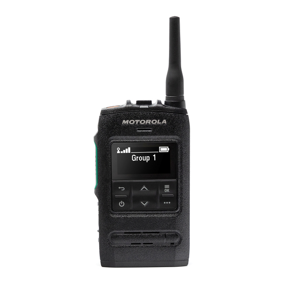
Page 83: St7500 Controls And Indicators
MN004527A01-AG Chapter 3: Man-Machine Interface ST7500 Controls and Indicators The simple-to-use controls and indicators of ST7500 allow you to quickly read and respond to alerts received on the radio. Figure 12: ST7500 Controls and Indicators Table 17: ST7500 Controls and Indicators... - Page 84 MN004527A01-AG Chapter 3: Man-Machine Interface Annotation Description Emergency Button Used to start the Emergency Operations, even when the radio is turned off. P1 Programmable Button Supports the One-Touch Button feature. Push-to-Talk (PTT) button Used to initiate a simplex call. NOTICE: Pressing PTT activates the display for three seconds. Volume button Increases or decreases the volume by pressing + or -.
-
Page 85: Keypad Lock
MN004527A01-AG Chapter 3: Man-Machine Interface Annotation Description PMOLED Display The 1.54-inch screen features a monochrome display with a resolution of 128 x 64 pixels. The screen consists of a two-line display area with the top line showing radio icons and the bottom line showing text. Earpiece The Earpiece is active during low-audio simplex or duplex calls. -
Page 86: Automatic Keypad Lock
MN004527A01-AG Chapter 3: Man-Machine Interface Automatic Keypad Lock The automatic keypad lock is a feature enabling the radio to lock its keypad automatically after a defined period. The radio allows activating or deactivating the feature using the MMI. If the feature is enabled, after a defined time of inactivity the keypad locks automatically. Any user activity restarts the Automatic Keypad Lock timer. - Page 87 MN004527A01-AG Chapter 3: Man-Machine Interface Feature Description Display Operational-Tacti- Displays the OPTA. cal Address (OPTA) Display Time Displays universal time on the home screen. DMO Pre-emptive Short Sends the next DMO SDS or status message with elevated priority. Data Service (SDS) Enable/Disable Howling Enables or disables Howling Suppression.
- Page 88 MN004527A01-AG Chapter 3: Man-Machine Interface Feature Description Select Talkgroup Network Displays the Select Talkgroup Network menu. Shortcut Selecting Audio Profiles Changes the audio profile of the radio. Send Double Push PTT Sends the D-PTT tone to the currently used talkgroup. Tone (D-PTT) Send Predefined Template Sends a predefined message to a dedicated address.
- Page 89 MN004527A01-AG Chapter 3: Man-Machine Interface Feature Description Toggle Hi or Low Audio Toggles audio between the external earpiece and the main speaker. Hi or Low Audio is the default function for the lower Side button. NOTICE: This feature is supported in emergency Full Du- plex Private Calls (FDPC) mode.
-
Page 90: Display
MN004527A01-AG Chapter 3: Man-Machine Interface Display This section presents the default home screen elements of the radio. Figure 13: Default Home Screen with Icons Home Mode Network Range TalkGroup 13/04/20 13:37 Options Contacts Test Group Table 19: Display Annotation Description Status icon area Text display area Soft key area... -
Page 91: Status Icons
MN004527A01-AG Chapter 3: Man-Machine Interface 3.7.1 Status Icons Status icons appear when your radio is engaged in certain activities or when you have activated certain features. Table 21: Trunked Mode Operation (TMO) Icons Icon Description In Service No Service Signal Strength The more bars, the stronger the signal. -
Page 92: Table 23: General Icons
MN004527A01-AG Chapter 3: Man-Machine Interface Icon Description No icon During a radio-to-radio and gateway call. Table 23: General Icons Icon Description Low Audio Audio mode is changed to low. High Audio Audio mode is changed to high. Earpiece Connected Earpiece is connected to the radio. Battery Strength Indicates the charge of the battery. - Page 93 MN004527A01-AG Chapter 3: Man-Machine Interface Icon Description Indoor Location Suspended Indicates that Indoor Location operation is temporarily suspended. New Message Has Arrived Indicates that a new message has arrived. Normal Call-Out Alert Indicates Normal Call-Out alert. Normal Call-Out Alert Accepted Indicates that Normal Call-Out alert has been accepted.
-
Page 94: Idle Display
MN004527A01-AG Chapter 3: Man-Machine Interface Icon Description SIM End-to-End Encryption (E2EE) Solid – Indicates that the SIM Card E2EE is enabled in DMO Mode. Num- bers 1 and 2 point to the type of DMO Encryption keys that has been se- lected. -
Page 95: Languages Supported
NOTICE: If the Favorite Talkgroup is selected, an icon preceding it denotes it as TMO or DMO. • Time and Date Order and visibility of these items are also subject of the Configurable Idle Screen settings. 3.7.4 Languages Supported Table 24: Languages Supported Language ST7500 English Arabic Chinese (traditional) Croatian Danish Dutch Finnish French... -
Page 96: Tones
MN004527A01-AG Chapter 3: Man-Machine Interface Language ST7500 European Spanish Latin American Spanish Swedish Tones NOTICE: The radio has two tone packs which are the default Classic Tones and New Tones. Your service provider decides which tone pack is enabled. To listen to the audio signal tones... -
Page 97: Description Of Tones
(when there is no received or transmitted speech) dependent on its category and the features interaction. The ‘right’ tone or event loudness is an objective matter. Motorola Solutions TETRA terminal tones architecture is highly flexible and allows you to adjust the level of every tone-event (such as valid key- press) individually and at the same time to adjust the level of all events associated with a tone- category. -
Page 98: Dual Microphones
MN004527A01-AG Chapter 3: Man-Machine Interface be louder, softer, or at speech level. This option is available both for in idle (when there is no received or transmitted speech) and in-call (during received or transmitted speech). 3.10 Dual Microphones Each radio has two microphones. One at the top of the unit for dispatch (simplex) operation, and another at the bottom of the unit for duplex calls. -
Page 99: Audio Features
MN004527A01-AG Chapter 3: Man-Machine Interface The Accry Setup menu contains the supported accessories, represented by their Model Number as defined by the related Audio Device Descriptor (ADD). ADD is a set of parameters in the radio that defines the audio settings, such as gains and filters settings, for each accessory. IMPORTANT: Do not connect RSMs to both connectors at the same time. - Page 100 MN004527A01-AG Chapter 3: Man-Machine Interface EquipID – TETRA Equipment Identity (TEI). LLS version – Local Language Package version. Antenna Frequency Band Flashtrap Ver UCM Ver • Addresses Home MNI – country identification code, network code. Group ID – number of the currently selected talkgroup. Own ISSI –...
-
Page 101: Radio Info
Individual Short Subscriber Identity (ISSI) – the ISSI that is in use. • TETRA Equipment Identity (TEI) – the TEI is displayed as a hexadecimal number. • Serial number – Motorola Solutions serial number is displayed only on radios distributed under Motorola Solutions trademark. 3.17 Hardware Test This mode allows performing basic hardware tests and share the results immediately on the display. -
Page 102: Appendix A: Maintenance
IMPORTANT: To avoid compromising the ingression protection of IP67, do not remove the seal label at the side of the radio. See ST7500 Controls and Indicators on page NOTICE: To ensure optimum ingression protection of IP65 and IP67, you are recommended to change the battery cover after two years of usage. -
Page 103: Figure 14: Areas To Keep Dry
You can also clean and protect the contacts with a CAIG DeoxIT GOLD G100P Pen Applicator Motorola Solutions recommends the pen-based package for better cleaning action and access to contacts. The CAIG DeoxIT GOLD G100P Pen Applicator is available at numerous electronics suppliers... - Page 104 MN004527A01-AG Appendix A: Maintenance Before applying the lubricant/cleaner, wipe the contacts with lint-free swabs to remove any dirt or foreign material. Then, clean the bottom connector contact as per the instructions from the DeoxIT GOLD manufacturer.
-
Page 105: Appendix B: Service Information - Emea
Customer Information Desk and obtain a Return Material Authorization number. Unless advised otherwise, the equipment should then be shipped to the following address: Motorola Solutions Systems Polska Sp.z o.o ul. Czerwone Maki 82, 30-392 Krakow, Poland. E-mail: escc.admin@motorolasolutions.com. - Page 106 Fax: +49 (0) 6128 951046 Latest Versions of Manuals To download the latest versions of technical manuals, see http://emeaonline.motorolasolutions.com. Submit Your Comments If you have any comments or would like to report a problem regarding Motorola Solutions publications, send an e-mail to: escc.admin@motorolasolutions.com.
-
Page 107: Appendix C: Service Information For Apac
If a unit requires further complete testing, knowledge and/or details of component level troubleshooting or service than is customarily performed at the basic level, send the radio to a Motorola Solutions Service Center as listed in the following table: Table 29: Service Information –... - Page 108 3220 Sukhumvit Road, Klongtoey, Bangkok 10110 Contact: Nitas Vatanasupapon E-mail: Nitas@motorolasolutions.com India +91-9844218850 Motorola Solutions India Pvt. Ltd. C/o Communication Test Design India Private Limited, #4, 5 Maruthi Industrial Estate, Rajapalya, Hoodi Village, Bangalore - 560048, India Contact: K. Umamaheswari E-mail: umamaheshwari@motorolasolutions.com...
- Page 109 Some replacement parts, spare parts, and/or product information can be ordered directly. If a complete Motorola Solutions part number is assigned to the part, it is available from Motorola Solutions Service Organization. If no part number is assigned, the part is not normally available from Motorola Solutions.
-
Page 110: Appendix D: Service Information - Americas
Motorola Solutions. If the part number is appended with an asterisk, the part is serviceable by Motorola Solutions Depot only. If a list of parts is not included, that means that no user-serviceable parts are available for that kit or assembly. - Page 111 Piso 11, San Isidro Lima 27 954-723-8959 Motorola Solutions, Inc. Latin American Countries Region 789 International Parkway Sunrise, FL 33325 Venezuela 58212-901-4600 Motorola Solutions de Los Andes C.A. Ave. Francisco de Miranda Centro Lido, Torre A Piso 15, El Rosal Caracas, 1060...
-
Page 112: Glossary
MN004527A01-AG Glossary Glossary Air Interface (AI) Class The radio-based Class. communication data transmitted over the air Synonym:Security Class between the mobile and the active base station. See also: Class 1 Air Interface Encryption (AIE) No encryption, may use Provides authentication. confidentiality on the radio link over the air. - Page 113 MN004527A01-AG Downlink Direct Mode Operation (DMO) Direct Flashing Writing a software image file to a communications between two or more radios without the use of any infrastructure. radio. Group Call A call addressed to talkgroups or Downlink The radio frequency multigroups.
- Page 114 MN004527A01-AG Location Request/Response Protocol Local Site Trunking (LST) Modified Group Cipher Key (MGCK) When a system fails or many of the sites lose connection Used to encrypt group addressed downlink to the Central Network Equipment (CNE), the signaling. sites are designed to go into a fall back situation See also: known as Local Site Trunking (LST).
- Page 115 MN004527A01-AG Public Switched Telephone Network information to be passed from TETRA Switching and Management Infrastructure (SwMI) to the Remote Flashing Programming the external network user and from the external transceiver through the control head. network user to the TETRA SwMI in accordance with the TETRA Call Control (CC) procedures.
- Page 116 MN004527A01-AG Talkgroup components excluding the mobile equipment that is the CNE and all the remote site equipment. Synonym:Fixed Network Equipment Talkgroup A uniquely named group of radios that can share calls and messages. A talkgroup’s normal communications do not require interfacing with other talkgroups.