Advertisement
Quick Links
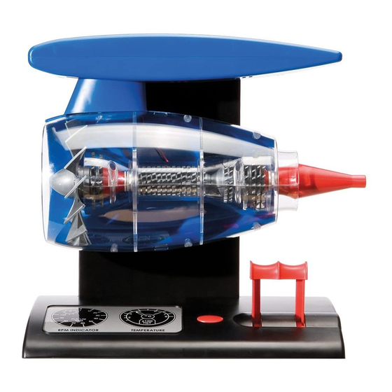
A20005
Jet Engine
Batteries required:
4 x 1.5 V - (Not included)
Please retain these instructions and the address for future reference
A
Product
Hornby Hobbies Limited, Margate, Kent CT9 4JX UK Tel:+44(0)1843 233525 www.airfix.com
Hornby Hobbies 4/A20005A - R1 0610
Advertisement

Summary of Contents for AIRFIX A20005
- Page 1 A20005 Jet Engine Batteries required: 4 x 1.5 V - (Not included) Please retain these instructions and the address for future reference Product Hornby Hobbies Limited, Margate, Kent CT9 4JX UK Tel:+44(0)1843 233525 www.airfix.com Hornby Hobbies 4/A20005A - R1 0610...
- Page 2 Battery Safety Guidelines Kit Parts - Engine Fan Blades Identify all the component parts Used correctly, domestic batteries are a safe and dependable source of portable and study the assembly sequences power. Problems can occur if they are misused or abused – resulting in leakage thoroughly before comencing or, in extreme cases, fire or explosion.
- Page 3 jet engine Kit Parts - Circuit board and voltage regulator, power switch and fan motor Assembly sequence 64 Note: Batteries are not supplied Four batteries,1.5 volt - size C, are required to operate the completed Jet Engine model To ensure a power suppy to the motor, the batteries must be correctly installed into the battery compartment as indicated...
- Page 4 jet engine Assembly sequence 58 Assembly sequence 1 Assemble the engine turbine/ Locate the push button into the top compressor blades unit into the cover with the cut-out positioned outer engine casing half. to the top of the push button Assembly sequence 59 Assembly sequence 2 Assemble the inner engine casing...
- Page 5 jet engine Assembly sequence 7 Position the lever arms, voltage Assembly sequence 52 regulator and circuit board into the base unit Assemble the 1st stage compressor blades, numbers 1 and 2, the cone, spacer and spindle washer onto the spindle as indicated. Please make sure that you assemble the correct size blades (SHORT).
- Page 6 jet engine Assembly sequence 13 Assembly sequence 46 Slide the shrink sleeve over folded exposed cable ends Push the air directional tubing through the lower aerofoil half and BLACK position the motor housing onto its cradle Assembly sequence 14 Assembly sequence 47 Apply heat using a hair dryer to secure the shrink sleeve in position Motor housing and air directional...
- Page 7 jet engine Assembly sequence 19 Assembly sequence 40 Push the collar of the air directional The battery cover securing nut and tubing onto the fan motor housing blanking plug are positioned into unit. the aperture as indicated in assembly sequences 20 and 21 Note: The collar is recessed to fit onto the motor housing.
- Page 8 jet engine Assembly sequence 25 Assembly sequence 34 Secure the pylon to the lower Locate the top cover and support aerofoil half using two screws with unit onto the base unit and place integral washers the control levers through the holes in the top cover Assembly sequence 35 Assembly sequence 26...
- Page 9 jet engine Assembly sequence 28 Assembly sequence 31 Secure pylon halves using two Thread the motor electric cables screws through the hole in the top of the upright support unit Assembly sequence 29 Assembly sequence 32 Position and secure the upright Thread the electric cables through support rear cover onto the upright the lower aerofoil as indicated...
- Page 10 jet engine Assembly sequence 22 Assembly sequence 37 Push the location pins to the upright Assemble the fan blower air support, into the top cover location directional tubing as indicated holes Ensure the vertical down tube with Note: Ensure the pins to the upright locating notch (clear solid plastic) support are the correct way around engages with the cut-out in the...
- Page 11 jet engine Assembly sequence 16 Assembly sequence 43 Push the exposed cable end Connect the exposed cable ends to through the hole in the battery the wires from the motor housing by terminal post twisting them together as indicated Red to Red and Black to Black BLACK Assembly sequence 17 Assembly sequence 44...
- Page 12 jet engine Assembly sequence 10 Assembly sequence 49 Twist the exposed cable ends Secure the aerofoil halves together together using four screws BLACK Assembly sequence 11 Assembly sequence 50 Cut a length of shrink sleeve and Assemble the large front fan slide over the cables engine blades Assembly sequence 12...
- Page 13 jet engine Assembly sequence 4 Assembly sequence 55 Insert the battery terminals inside Push the tailcone halves together the battery aperture as indicated Ensure the terminals with connection posts are pushed firmly into their location slots with their posts protruding through the box cover Assembly sequence 5 Assembly sequence 56...
- Page 14 jet engine Assembly sequence 61 Kit Parts - Engine casings, air ducting elbow and down tube Assemble the turbine blade and engine casing into the inner engine nacelle locating the casing lug into the nacelle notch. Note: Secure the electric cabling with adhesive tape into the engine nacelle as indicated Kit Parts - Turbine blade spindle, shrink sleeve...
- Page 15 jet engine Kit Parts - Lower and Upper Aerofoils Assembly sequence 67 Using a cross head screw driver,tighten the bolt to secure the cover plate to the base Kit Parts - Base and Cover Assembled kit To operate the Jet Engine, press the button to start the motor and then rotate the lever handle to increase or decrease the power to...
- Page 16 Notes jet engine The Jet Engine the front of the engine through the forward compressor. As the gases rush out of the jet engine developed engine this causes the engine to move for- simultaneously by Great Britain and Germany ward, this is based on the famous scientist in the 1930s.
Need help?
Do you have a question about the A20005 and is the answer not in the manual?
Questions and answers