Table of Contents
Advertisement
Model No.: XG1136224169002
Owner's Manual
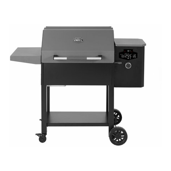
Expert Grill Commodore
A MAJOR CAUSE OF FIRES IS FAILURE TO MAINTAIN
REQUIRED CLEARANCES (AIR SPACES) TO
COMBUSTIBLE MATERIALS. IT IS OF UTMOST
IMPORTANCE THAT THIS PRODUCT BE INSTALLED ONLY
IN ACCORDANCE WITH THESE INSTRUCTIONS.
READ ALL INSTRUCTIONS BEFORE INSTALLING AND USING THE APPLIANCE
Failure to follow these instructions could result in property damage, bodily injury or even death.
Contact local building or fire officials about restrictions and installation inspection requirements in your area.
SAVE THESE INSTRUCTIONS
For Outdoor Use Only
If you have any questions or problems, you can contact our customer service at 855-256-2160 or
expertgrill@grillservices.net from 8 AM – 4:30 PM Eastern Time, Monday to Friday
- 1 -
Advertisement
Table of Contents

Related Manuals for EXPERT GRILL Commodore


Summary of Contents for EXPERT GRILL Commodore
- Page 1 Model No.: XG1136224169002 Owner’s Manual Expert Grill Commodore A MAJOR CAUSE OF FIRES IS FAILURE TO MAINTAIN REQUIRED CLEARANCES (AIR SPACES) TO COMBUSTIBLE MATERIALS. IT IS OF UTMOST IMPORTANCE THAT THIS PRODUCT BE INSTALLED ONLY IN ACCORDANCE WITH THESE INSTRUCTIONS.
-
Page 2: Table Of Contents
Table of Contents WARNING....................- 1 - Parts Diagram....................- 3 - Assembly Steps..................- 5 - Use of the Pellet Grill................- 15 - Placement of the Device..............- 15 - Outdoor Cooking Pellets..............- 15 - Confirmation before Powering on.............- 15 - Button Function Description............. -
Page 3: Warning
※Use Only Wood Pellet Fuel Specified By EXPERT GRILL. Do Not Use Pellet Fuel Labeled As Having Additives. ※Remove pots and pans while the operating appliance is unattended, to reduce the risk of fire. - Page 4 ※When grease or creosote has accumulated , it should be removed to reduce risk of fire. ※Do not burn for a long time to prevent the product from overheating. ※Remove the POP labels before using the grill. WARNING When installed, must be electrically grounded in accordance with local codes or, in the absence of local codes, with the National Electrical Code, ANSI/NFPA 70, or the Canadian Electrical Code, Part I, CSA C22.1.
-
Page 5: Parts Diagram
Parts Diagram - 3 -... - Page 6 - 4 -...
-
Page 7: Assembly Steps
Hardware Tools required for assembly Philips Head Screwdriver (not included). Assembly Steps Parts Required: Locking Caster (Part #14) x2 Left Front Leg (Part #12) x1 Left Rear Leg (Part #13) x1 Installation: Insert Locking Caster (Part #14) stem into bottom of Left Front Leg (Part #12). - Page 8 Parts / Hardware Required: Left Front Leg (Part #12) x1 Left Rear Leg (Part #13) x1 Firebox Body (Part #2) x1 (Hardware B) x4 (Hardware C) x4 Installation: Insert the Left Front Leg (Part #12) and Left Rear Leg (Part #13) into Firebox Body (Part Use 4 screws (Hardware B) and...
- Page 9 Parts / Hardware Required: Bottom Shelf (Part #11) x1 (Hardware B) x4 Installation: Attach Bottom Shelf (Part #11) to legs using 4 screws (Hardware B) from underside of shelf. Parts / Hardware Required: Wheel Axle (Part #8) x1 ...
- Page 10 Hardware Required: (Hardware B) x4 (Hardware C) x4 Installation: Open the Hood. Use 4 screws (Hardware B) and 4 washers (Hardware C) as shown. Note: The washers concave side down when install. Parts / Hardware Required: Hood Handle (Part #1) x1 ...
- Page 11 Parts / Hardware Required: Grease Tray Bracket (Part #22) x2 (Hardware A) x4 Installation: Mount Grease Tray Bracket (Part #22) Use 4 screws (Hardware A) Parts Required: Grease Tray (Part #19) x1 Foil Liner (Part #20) x1 ...
- Page 12 Parts / Hardware Required: Grease Guide Assembly (Part #18) x1 (Hardware A) x2 Installation: Mount Grease Guide Assembly (Part #18) Use 2 screws (Hardware A) Parts / Hardware Required: Side Shelf (Part #17) x1 (Hardware B) x4 ...
- Page 13 Parts Required: Ash Clean-out Cover (Part #21) x1 Installation: There are two ears on the back side of Ash Clean-out Cover (Part #21). Put this cover into the hole, with 2 ears at orientation shown, then turn 90 degree as shown. Parts Required: Flame Tamer (Part #3) x1 ...
- Page 14 Parts Required: Grease Drain Pan (Part #4) Installation: Mount Grease Drain Pan (Part #4) on the firebox. The tab should be placed as shown. Parts Required: Searing Station Pull Handle (Part #6) x1 Installation: Insert Searing Station Pull ...
- Page 15 Parts Required: Warming Rack (Part #16) x2 Cooking Grid (Part #15) x2 Parts / Hardware Required: Power Cord Bracket (Part #23) x2 (Hardware F) x2 Installation: Insert Power Cord Bracket (Part #23) through slots in backside of Hopper Assembly.
- Page 16 Parts Required: Meat Probe (Part #5) x1 Installation: Plug the end of meat probe into P1 or P2 port under hopper cap. When a meat probe is connected, the temperature is displayed on the PID screen. When not in use, unplug the meat probe from the connection port.
-
Page 17: Use Of The Pellet Grill
Use of the Pellet Grill Placement of the Device Pellet grills should be placed outdoors in an open and ventilated place with a minimum distance of 2FT on the sides and back. And this clearance must be maintained while the grill is operational. This appliance must not be placed under overhead combustible ceiling or overhang. -
Page 18: Button Function Description
When a meat probe is connected, the temperature is displayed on the PID screen. When not in use, unplug the meat probe from the connection port. There are two (2) connection port(s). Compatible with EXPERT GRILL® branded meat probes only. Additional meat probe(s) sold separately. - Page 19 Press and turn the control knob (When "SET" selected as shown ) to select your desired temperatures, between 180 F~450 ° ° This Bluetooth icon will flash after the grill is turn on. It will stop flashing when the device is connected with your phone. This icon will always light after the grill is turn on.
-
Page 20: Ignition Instructions
Ignition Instructions Before powering on the device, you should re-confirm the safety of surrounding power environment, and there is no damp or bare wire in the socket and plug. Open the pellet hood, check the fire pot to ensure there is no obstruction for proper ignition. Before each ignition, please clean up the residual ash in the fire pot. -
Page 21: Cooking Instructions
Cooking Instructions Breaking In the Grill Before cooking on your grill for the first time, it is important to start the grill and operate at 350 ° for half an hour to season the grill. Cooking Once the grill is ignited, you can begin cooking by selecting any of the cooking temperatures. Cooking should be done with the hood closed only. -
Page 22: Ashes Clean-Out
Ashes Clean-out Before each time to use grill or after used (must let grill cool down completely), remove cooking grids, grease drain pan and flame tamer successively. Fire Pot Ashes Clean-out 1. Loosen the buckles of fire pot. 2. Take out the fire pot and discard the ashes. WARNING: Before disposing of Ashes, make sure the ash is completely free of hot embers to prevent possible fire. -
Page 23: Pellet Hopper Clean-Out
Pellet Hopper Clean-out If grill will be left un-attended for a long period of time, we recommend you remove unused pellets. Always store wood pellets away from heat and in a dry location. 1. lift Clean-out handle Lock 2. Open Hopper Clean-out door Note: Make sure to hold a pail or bag in place before emptying pellets. -
Page 24: Connection Of The App
Connection of the App 1. Search " Expert Grill" in iOS store or Play store to download the APP. 2. After download the APP, initiate Bluetooth function of your phone, on PID screen will stop flashing when the device is connected with your phone, and click the APP to search the devices. - Page 25 5. Functions on main interface Turn on/off This button can switch between Celsius and Fahrenheit. Push this button can start the forced feeding. The PID screen "Prime" will become red. These are not touchable icons, they will display same status as on PID screen.
-
Page 26: Troubleshooting
Troubleshooting WARNING:Before troubleshooting, make sure the power is turn off, the grill in turn off. Problem Cause Solution PID Screen Grill is not Ensure all wire connections are Not Turn ON properly plugged firmly connected. Ensure grill is plugged into a working GFCI outlet. - Page 27 “ErL” Insufficient or Check and remove fire pot ash poor pellets build-up, obstructions and that it is seated properly in the firebox. Ensure igniter is heating up and positioned correctly. Check fans to confirm operation and speed. ...
- Page 28 Frequent Cooking Set the temperature lower. Flare- ups temperature Grease does have a flash point, is too high keep the temperature under 350°F when cooking highly greasy food. Excess Check and clean the interior grease grilling area.
- Page 29 Input Voltage :AC110V ~ AC120V 60HZ Max power :250W Power of auger :25W ±10% Power of fan :25W ±10% Power of fire rod :200W ±10% Probe type :PT1000 Display : Wiring diagram : Red white(auger),yellow white(fan),purple white(fire rod),black white(power cord) - 27 -...
-
Page 30: Warranty
Warranty Two-Year Full Warranty If this grill fails due to a defecting material or workmanship within one year from the date of purchase, call 855-256-2160 to arrange for free repair (or replacement if repair proves impossible). All warranty coverage excludes ignitor and grill part paint loss, discoloration, or rusting, which are either expendable parts that can wear out from normal use within the warranty period, or are conditions that can be the result or normal use, accident, or improper maintenance.
Need help?
Do you have a question about the Commodore and is the answer not in the manual?
Questions and answers