
Related Manuals for Riken Keiki SD-1EC


Summary of Contents for Riken Keiki SD-1EC
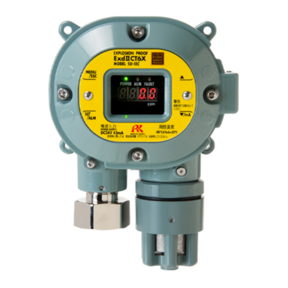
- Page 1 PT2E-17610 Smart Transmitter/Gas Detector Head SD-1EC Operating Manual (PT2E-176) (PT2-176)
- Page 2 Operating Precautions This detector is a gas detector that detects toxic gases in the air and triggers a gas alarm. The gas detector is a safety unit, not an analyzer or densitometer which performs quantitative/qualitative analysis/measurement for gases. Please fully understand the following points before using it, so that it can be used properly. 1.
-
Page 3: Table Of Contents
<Contents> 1 Outline of the Product ......................2 1-1. Preface ..........................2 1-2. Purpose of use ........................2 1-3. Definition of DANGER, WARNING, CAUTION, and NOTE ..........2 1-4. Method of confirmation for Standards and Explosion proof specification ......3 2 Important Notices on Safety.................... -
Page 4: Outline Of The Product
Outline of the Product 1-1. Preface Thank you for choosing our smart transmitter/gas detector head SD-1EC. Please check that the model number of the product you purchased is included in the specifications on this manual. This manual explains how to use the detector and its specifications. It contains information required for using the gas detector properly. -
Page 5: Method Of Confirmation For Standards And Explosion Proof Specification
1 Outline of the Product 1-4. Method of confirmation for Standards and Explosion proof specification 1-4. Method of confirmation for Standards and Explosion proof specification This instrument has some specification depends on standard and explosion proof certificate. Please confirm the detector specification before using. Please refer Declaration of Conformity that is at the end of this manual if you have CE marking type. -
Page 6: Important Notices On Safety
“10-1. List of specifications” for details.) Do not replace parts at your sole discretion but contact RIKEN KEIKI if the transparent window has a crack or the explosion-proof joint surface is abnormal, or the clamping screw or bolt is changed, lost etc. -
Page 7: Warning Cases
2 Important Notices on Safety 2-2. Warning cases 2-2. Warning cases WARNING Power supply Before turning on the detector, always check that the voltage is properly applied. Do not use an unstable power supply because it may cause malfunctions. Need of grounding circuit Do not cut the grounding circuit or disconnect the wire from the grounding terminal. -
Page 8: Precautions
2 Important Notices on Safety 2-3. Precautions 2-3. Precautions CAUTION Do not use a transceiver near the detector. Radio wave from a transceiver or other radio wave transmitting device near the detector or its cables may disturb readings. If a transceiver or other radio wave transmitting device is used, it must be used in a place where it disturbs nothing. -
Page 9: Safety Information
Necessary information for explosion proof construction of Model SD-1EC. The Model SD-1EC is a fixed mount, continuous-monitoring detector head and provides a 4-20mA signal which indicates the target gas reading for use by a gas monitoring controller, recording device, or programmable controller. - Page 10 2 Important Notices on Safety 2-4. Safety Information <TIIS Specifications> Technical Data (Protection Method) Flameproof enclosure (Explosion-proof class) Ex d llC T6 X (Ambient Temperature)* -20C to +53C (Electrical Data) Supply voltage: DC24V±10% 45mA Detecting element output signal: DC0.5V 0.5mA Analog signal output: DC24V 22mA Contact output (Contact capacity): AC250V 0.5A (Load resistance) DC30V 0.5A (Load resistance)
-
Page 11: Product Components
3 Product Components 3-1. Gas detector and standard accessories Product Components 3-1. Gas detector and standard accessories <Main Unit> (including a cable gland or an adapter) 【ATEX/IECEx Specifications】 Adapter (NPT 1/2 ) 【TIIS Specifications】 - 9 -... -
Page 12: Names And Functions For Each Part
3 Product Components 3-2. Names and functions for each part <Standard Accessories> Operating manual・・・・・・・・・・・・・・・・・・ one Dedicated handling lever ・・・・・・・・・・・ one Dedicated control key・・・・・・・・ The supplied quantity depends on the number of units to be delivered. 1 to 10 units 11 to 20 units 21 to 50 units three over 51 units... -
Page 13: Block Diagram
3 Product Components 3-3. Block diagram 3-3. Block diagram <Electric Diagram> Power supply part POWER INPUT (24 VDC) Display (POWER) (ALARM) (FAULT) Controller Seven-segment LED Alarm contact controller (CPU) (four-digit) 1. Gas alarm contact (ALARM) Magnetic operation part 2. Fault contact (FAULT) (MENU/ESC) (▲) (▼) (SET) 3. -
Page 14: How To Use
4 How to Use 4-1. Before using the detector How to Use 4-1. Before using the detector Not only the first-time users but also the users who have already used the detector must follow the operating precautions. Ignoring the precautions may damage the gas detector, resulting in inaccurate gas detection. 4-2. -
Page 15: Precautions For System Designing
4 How to Use 4-3. Precautions for system designing Do not install the detector in a place where maintenance of the detector cannot be performed or where handling the detector involves dangers. Regular maintenance of the detector must be performed. Do not install the detector in a place where the machinery must be stopped when maintenance is performed in its inside, where parts of the machinery must be removed to perform maintenance, or where the detector cannot be removed because tubes or racks prevent access to it. - Page 16 It may be recommended that the surge absorbing part should be attached to the contact for certain load conditions. It must be attached to an appropriate position by checking how the load is activated. SD-1EC Power Power supply supply...
-
Page 17: How To Install
When closing the lid of the detector, make sure that there is no dust on screw, surfaces of the main body and lid. Then apply grease as specified by RIKEN KEIKI. CAUTION Do not install the detector in a place where maintenance of the detector cannot be performed or where handling the detector involves dangers. - Page 18 ・Hexagon socket head cap bolt with strength class "A2-70" are used. When you lost or replace it, we recommend that you ask our local sales office nearest you. ・Grease specified by RIKEN KEIKI : BARRIERTA JFE 552 (manufactured by NOK KLUBER) If you can not prepare the specified grease, use one that meets the following requirements.
-
Page 19: Installation Procedure
Adapter A (NPT1/2) 【TIIS Specifications】 Cable gland, Rubber seal, Washer and Eccentric washer are mounted on SD-1EC main body as shown below. Attach the parts : Pass a Cable (e.g. CVVS) through the Cable gland, Eccentric washier, Washer, and Rubber seal, and drawn into detector inside. - Page 20 4-5. Installation procedure WARNING Do not replace parts at your sole discretion but contact RIKEN KEIKI if the transparent window has a crack or the explosion-proof joint surface is abnormal, or the clamping screw or bolt is changed, lost etc.
-
Page 21: How To Wire
4 How to Use 4-6. How to wire 4-6. How to wire CAUTION Be careful not to damage the internal electronic circuit when wiring. In addition, be careful not to apply stresses on the detector when (overweight) cables are installed. ... - Page 22 4 How to Use 4-6. How to wire <Figure of Terminal Plate> 24 VDC - (Common) 4 - 20 mA Sig+ Contact Contact Grounding terminal <Specifications of Terminal Plate> Specifications of terminal plate Rated voltage: 250 VAC Rated current: 12 A However, it depends on cables to be used.
- Page 23 4 How to Use 4-6. How to wire CAUTION The specified bare wire length must be observed when the wire insulation is peeled off. Improper clamping of the wire due to a shorter bare wire length may cause defective electric conduction or heating.
- Page 24 Use ring terminals to connect the grounding terminal with the ground and use the grounding wire with cross-sectional area of 4 mm or more for the external grounding terminal. <Wiring Example> Connecting to the indicator SD-1EC 2 3 4 5 RM-5003 etc. +24 V Connecting to the upper unit (DCS, PLC)
-
Page 25: How To Operate
5 How to Operate 5-1. Preparation for start-up How to Operate 5-1. Preparation for start-up Before connecting a power supply, read and understand the following precautions. Ignoring these precautions may cause an electric shock or damage the detector. Connect the detector to a grounding circuit. ... -
Page 26: How To Start The Detector
5 How to Operate 5-3. How to start the detector WARNING When the detector enters other mode from the detection mode while an alarm is activated, the alarm is reset. 5-3. How to start the detector Before supplying power (24 VDC) to the detector, check that the detector is installed properly. ... - Page 27 5 How to Operate 5-4. Modes 5-4. Modes Details on each mode are provided as follows. CAUTION Do not change the settings if not necessary. Changing the settings without understanding the specifications may cause malfunctions. Mode Item Details display Detection Mode concentr Normal state...
-
Page 28: Maintenance Mode (User)
5 How to Operate 5-5. Maintenance mode (User) 5-5. Maintenance mode (User) WARNING After the adjustment is completed, never fail to press MENU/ESC key to return to the detection mode. (If the detector remains in the user mode, it automatically returns to the detection mode in ten hours.) Detection Mode Press the MENU/ESC key for... - Page 29 5 How to Operate 5-5. Maintenance mode (User) <Zero Adjustment "1-1"> This is used to perform the zero adjustment. Press SET key. Current Concentration Value Display Press the SET key to perform the zero adjustment. Under Zero Adjustment (CAL. is displayed) Wait for a while until the adjustment is completed.
-
Page 30: How To Exit
5 How to Operate 5-6. How to exit <Setting Display "1-2"> Display various setting values. 1-2. Press SET key. Alarm Setpoint Display Alarm Delay Time Display (seconds) Zero Suppression Value Display : The contact is activated due to the Alarm Contact Specification gas alarm. -
Page 31: Operations And Functions
6 Operations and Functions 6-1. Gas alarm activation Operations and Functions 6-1. Gas alarm activation Gas alarm: Activated when the concentration of detected gas reaches or exceeds the alarm setpoint value. <<Auto-Reset Operation>> NOTE The alarm setpoint is factory-set. Although the alarm delay time (standard: 2 seconds) works in the detector to prevent a false activation, it can be cancelled if not needed. -
Page 32: Fault Alarm Activation
After the detector is successfully returned from the fault, it restarts with the process normally performed right after it is turned on (initial clear). If the detector has problems and is repeatedly malfunctioning, contact RIKEN KEIKI immediately. <Display Operation> Fault Detail Display Display a message indicating the fault detail. -
Page 33: External Output Operation
6 Operations and Functions 6-3. External output operation 6-3. External output operation Signal Transmission System Electric current transmission (non-isolated) 4 – 20 mA Transmission Path CVVS Transmission Distance CVVS 1.25 mm : Maximum 1.25 km CVVS 2.0 mm : Maximum 2.0 km Connection Load Resistance Below 300 Ω... -
Page 34: Other Functions
6 Operations and Functions 6-4. Other functions 6-4. Other functions <Suppression Function> The sensors used with the detector are influenced by environmental changes (temperature, humidity and other characteristics) or interference gases (interference characteristics) in no small measure, which affects the reading. Therefore, the reading might be fluctuated around zero even in a normal environment. This function obscures influences by environmental changes and interference gases around zero that have no meaning for your management rules of gas alarm. -
Page 35: Maintenance
7 Maintenance 7-1. Maintenance intervals and items Maintenance The gas detector is an important instrument for the purpose of safety. To maintain the performance of the gas detector and improve the reliability of safety, perform a regular maintenance. 7-1. Maintenance intervals and items ... - Page 36 7 Maintenance 7-1. Maintenance intervals and items Main Services Power Supply Checks the power supply voltage. Check Verifies that the power lamp lights up. (Verifies that relevant points can be identified on the system.) (When a UPS (uninterruptible power system) is used, checks the operation with the UPS.) Concentration Verifies that the concentration display value is zero by using the zero gas.
-
Page 37: Maintenance Mode(Regular Maintenance)
7 Maintenance 7-2. Maintenance Mode(Regular maintenance) 7-2. Maintenance Mode(Regular maintenance) WARNING After the adjustment is completed, never fail to press MENU/ESC key to return to the detection mode. (If the detector remains in the regular maintenance mode, it automatically returns to the detection mode in ten hours.) Mode Item... - Page 38 7 Maintenance 7-2. Maintenance Mode(Regular maintenance) 2-1. Zero Adjustment Zero Adjustment => P42 Perform the zero adjustment. Span Adjustment => P44 2-2. Span Adjustment Perform the span adjustment. 2-3. Zero/Span Initialization Initialize the zero/span adjustment after the sensor is replaced. Environmental Setting 2-4.
- Page 39 7 Maintenance 7-2. Maintenance Mode(Regular maintenance) <Test Mode "2-0"> Press SET key. 2-0.0 Gas Test Gas Test => P38 2-0.1 Alarm Test Alarm Test => P38 2-0.2 Fault Test Fault Test => P39 2-0.3 LED Test LED Test => P39 2-0.4 Memory Test Memory Test =>...
- Page 40 7 Maintenance 7-2. Maintenance Mode(Regular maintenance) <Gas Test "2-0.0"> 2-0.0 Press SET key. Introduce the test gas and perform the gas test. Stop introducing the test gas. When the reading drops, press the MENU/ESC key to cancel the test and to go back to the original state.
- Page 41 7 Maintenance 7-2. Maintenance Mode(Regular maintenance) <Fault Test "2-0.2"> 2-0.2 Press SET key. Fault Test ON/OFF Select either ON/OFF. Switch ON and press the SET key to trigger the fault alarm. Return to OFF and press the SET key to cancel the test.
- Page 42 7 Maintenance 7-2. Maintenance Mode(Regular maintenance) <Memory Test "2-0.4"> 2-0.4 Press SET key. When StA. is displayed, press the SET key again. When CAL. is displayed, the memory diagnosis is performed. When memory is correct as a result of the diagnosis, PASS is displayed.
- Page 43 7 Maintenance 7-2. Maintenance Mode(Regular maintenance) <Environmental Setting "2-4"> Set various operations and functions in the environmental setting. <<Environmental Setting 1>> 2-4. Environmental Setting Press SET key. 2-4.0 They are factory-set and not typically used by the user. 2-4.1 INHIBIT Setting Set Inhibit.
-
Page 44: Calibration Method
7 Maintenance 7-3. Calibration method 7-3. Calibration method Perform a calibration in each mode (zero adjustment mode and span adjustment mode) <SD-1EC> using the calibration gas. Zero adjustment gas Calibration gas (collected in a gas sampling bag) ... - Page 45 7 Maintenance 7-3. Calibration method Press SET key. Current Concentration Value Display Press the SET key to perform the zero adjustment. Under Zero Adjustment (CAL. is displayed) Wait for a while until the adjustment is completed. Zero Adjustment Completed It automatically returns to 2-1 after PASS is displayed.
- Page 46 If there are mistakes, perform the span adjustment again. If the span adjustment cannot be performed even when there is no mistake or after recalibration, the gas sensor life might have expired. After turning off the power supply, please contact RIKEN KEIKI. - 44 -...
-
Page 47: Parts Replacement
7 Maintenance 7-4. Parts replacement 7-4. Parts replacement <Sensor Replacement> Gas sensor replacement is according to the following procedures. (1) Turn off the power supply (24VDC) to the detector. (2) After loosened hexagon socket set screw(2 places) by hex wrench (nominal size 2), remove and turning sensor guard. - Page 48 The operation must be checked after replacement by a qualified service engineer. For the stable operation of the unit and safety, ask a qualified service engineer to take care of replacement of the parts that operation must be checked. Request RIKEN KEIKI for operation check. NOTE ...
-
Page 49: Storage, Relocation And Disposal
When using a relocated or stopped/stored detector again, never fail to perform a calibration. For information on readjustment including a calibration, please contact RIKEN KEIKI. 8-3. Disposal of products When the detector is disposed of, it must be treated properly as an industrial waste in accordance with the local regulations. -
Page 50: Troubleshooting
9 Troubleshooting Troubleshooting The Troubleshooting does not explain the causes of all the malfunctions which occur on the detector. This simply helps to find the causes of malfunctions which frequently occur. If the detector shows a symptom which is not explained in this manual, or still has malfunctions even though remedial actions are taken, please contact our overseas sales department or local representatives. - Page 51 9 Troubleshooting <Abnormalities of Readings> Symptoms Causes Actions Drifting of sensor Perform zero adjustment. output Presence of Disturbances by interference gases, such as solvents, interference gas cannot be eliminated completely. The reading rises (drops) A very small amount of the gas to be detected may be and it remains so.
-
Page 52: Product Specifications
10 Product Specifications 10-1. List of specifications Product Specifications 10-1. List of specifications <ATEX/IECEx Specifications> Model SD-1EC Detection principle Electrochemical method Detectable gas H2S/CO Gas concentration display LED(4digits・7segments) H2S:0 - 30ppm or 0 - 50ppm or 0 - 100ppm Measuring range CO:0 - 75ppm or 0 - 150ppm or 0 - 200ppm or 0 - 250ppm or 0 - 300ppm... - Page 53 10 Product Specifications 10-1. List of specifications Outline Drawings Adapter A (NPT 1/2 ) - 51 -...
- Page 54 10 Product Specifications 10-1. List of specifications <TIIS Specifications> Model SD-1EC Detection principle Electrochemical method Detectable gas H2S/CO Gas concentration display LED(4digits・7segments) Measuring range H2S:0 - 30ppm or 0 - 50ppm or 0 - 100ppm CO:0 - 75ppm or 0 - 150ppm or 0 - 200ppm or 0 - 250ppm or 0 - 300ppm...
- Page 55 10 Product Specifications 10-1. List of specifications Outline Drawings Cable gland (G3/4) - 53 -...
-
Page 56: Detection Principle
10 Product Specifications 10-2. Detection principle 10-2. Detection principle [Detection principle] An electrochemical type sensor electrolyzes a gas directly while maintaining the interface between electrode and electrolyte at a constant potential (bias voltage). A gas is electrolyzed by an electrolysis cell to which a certain potential (bias voltage) is applied, and the gas is detected from the electrolytic current generated at that time. -
Page 57: Definition Of Terms
11 Definition of Terms Definition of Terms Electrochemical This is a principle of the sensor installed in the detector head. type See "10-2. Detection principle" for details. Output from the detector head fluctuates for a while after turning on the power. Initial clear This is a function to prevent triggering alarm during that time.
Need help?
Do you have a question about the SD-1EC and is the answer not in the manual?
Questions and answers