Aulisa Guardian Angel GA1000 Series Instructions For Use Manual
Digital vital sign monitoring system
Hide thumbs
Also See for Guardian Angel GA1000 Series:
- Instructions for use manual (32 pages) ,
- Instructions for use manual (32 pages) ,
- Instructions for use manual (49 pages)

Related Manuals for Aulisa Guardian Angel GA1000 Series


Summary of Contents for Aulisa Guardian Angel GA1000 Series
- Page 1 Guardian Angel ® GA1000 Series Digital Vital Sign Monitoring System Instructions For Use ____________________________________________________________ 7MN00026-01...
-
Page 2: Disclaimer
Technologies, Inc. reserves the right to make changes and improvements to this manual and the products described within at any time, without notice or obligation. References to “Aulisa” in this manual shall imply Taiwan Aulisa Medical Devices Technologies, Inc. Aulisa is a registered trademark of Taiwan Aulisa Medical Devices Technologies, Inc. -
Page 3: Table Of Contents
Device Setting Up ......................14 Device Pairing ....................... 15 Automatic Pairing ....................15 Pairing with a new Aulisa sensor module ............15 Device Verification ....................... 16 Verify the device function ..................16 Verify the alarm function BEFORE each use ............16 Device Power Off...................... -
Page 4: Guide To Symbols
Guide to Symbols... -
Page 6: Welcome
Welcome This manual will help you get started with monitoring using Aulisa Guardian Angel ® GA1000 Series Digital Vital Sign Monitoring System (“GA1000S”) by introducing the Display Unit which is intended for use in conjunction with a variety of wearable Aulisa sensor modules. -
Page 7: Ga1000S Function
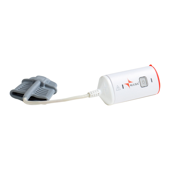
Aulisa sensor module(s) Display unit The Aulisa sensor module(s) is a wearable device intended for vital signs detection and physiological data transmission to the Display Unit via Bluetooth technology. The Display Unit receives and displays physiological data as well as generates alarms for technical errors or physiological events. -
Page 8: Precautions For Use
Precautions for Use Use this device only within its designated range (approximately 32.8 feet (10 meters)— spherical radius— from Aulisa sensor module(s) to this device). Moving outside this range may cause missing, lost, and/or inaccurate data. This device readings may be affected by the use of an electrosurgical unit. -
Page 9: Device Components
Device Components Display Unit with Aulisa application software Display Unit Stand Display Unit Charging Adapter (Type-C) -
Page 10: Device Overview
Device Overview The Display Unit features a 10 1" LCD multi-touch display with Bluetooth technology. The Display Unit displays real-time vital signs measured by Aulisa sensor module(s). The Display Unit will display informational text messages, alarm text messages, and beep made audible upon an alarm condition trigger event. - Page 11 Display Unit No data shows dashes “- - -” in each of the vital sign windows. This icon displays whether the Aulisa sensor module(s) and the Bluetooth Display Unit are connected via Connection Status Bluetooth. It will turn blue once the pairing succeeds.
- Page 12 Display Unit when the Display Unit battery level is low. These icons signify the battery level of Aulisa sensor module(s) Battery Level of at Full, Medium, or Low. Aulisa sensor A medium priority system alarm...
- Page 13 Brightness the display. In the Setting menu, tap on this button to adjust the alarm limits for each Aulisa sensor module. Set Alarm Limits NOTE: The alarm limits are adjustable only when the wireless connection is established.
- Page 14 Aulisa sensor module(s) to manually pair with the Display Unit. This button appears when an alarm is triggered. Tap on the button to temporarily silence Pause Alarm Audio the alarm audio of the current triggered alarm event for 2 minutes.
-
Page 15: Device Setting Up
Do not plug the adaptor into a switched outlet to prevent accidental switching power off. Step 4: Wait for the wireless connection between the Display Unit and the Aulisa sensor module(s) to be established. Once connected, the vital signs and the Aulisa sensor module(s) status information will appear on the MAIN screen. -
Page 16: Device Pairing
Step 1: In the Setting menu, select “PAIRING". Step 2: Scan the QR Code or key in the serial number located on the Aulisa sensor module(s). Step 3: Press “CONFIRM” if the serial number (SN) displayed matches with the one on the Aulisa sensor module(s). -
Page 17: Device Verification
Step 1: Set up the system. Refer to the Aulisa sensor module(s) Instructions for Use for setting up instructions. Step 2: Make sure Aulisa sensor module(s) is worn on or attached to the right place firmly. Step 3: Verify that the Bluetooth connection status icon on the Display Unit is blue and the status indicator on Aulisa sensor module(s) is blinking green. -
Page 18: Device Power Off
Step 1: Plug the Type-C end of the charging adaptor into the Display Unit. Step 2: Attach the wall adaptor to a power outlet. Step 3: Place the Display Unit on the stand provided. CAUTION!!! Only use adaptors supplied or manufactured by Taiwan Aulisa Medical Devices Technologies, Inc. -
Page 19: Alarms And Limits
Alarms and Limits Alarm Features The Display Unit provides high and medium priority audible and visual alarms. The visual alarm is indicated by the alarm window on the screen of the Display Unit. Audio alarms will sound from the speakers on the Display Unit. NOTE: The volume for audio alarms cannot be adjusted. - Page 20 High priority audio alarms are: 3 beeps, short pause, 2 beeps, short pause, 3 beeps, short pause, 2 beeps, and 5-second pause. This sequence repeats until the alarm is cleared or silenced. Tap on ʻʻPAUSE AUDIOʼʼ button to pause the alarm audio for 2 minutes. Tap on ʻʻAUDIO OFFʼʼ...
- Page 21 NOTE: The following table describes alarm conditions and visual indicators. Alarm Condition Visual Indicator (Medium Priority Alarm) Oximeter Sensor Probe Detached from the Finger The Oximeter Module blinks yellow along with blinking Oximeter Module Battery Low yellow displays and alarm text Oximeter Sensor Cable Detached message on the Display Unit.
- Page 22 Multiple Alarms When there are high and medium priority alarms triggered simultaneously, the system will display all the alarm text messages but will only sound the high priority alarm. CAUTION!!! Silencing alarms does not mean the situation has been resolved. CAUTION!!! Tapping on “AUDIO OFF”...
-
Page 23: Alarm Limits
Follow the instructions below to review or set alarm limits. Step 1: Ensure the Bluetooth connection is established. (See “Device Pairing” section.) Step 2: Tap on "SETTING" button on the MAIN screen, and then tap on “ALARM LIMITS” button. Select the designated Aulisa sensor module. - Page 24 NOTE: Alarm limits can be adjusted only when the Aulisa sensor module(s) is paired with the Display Unit. NOTE: In an alarm event, ʻʻALARM LIMITSʼʼ button will appear after you select "AUDIO PAUSE" button or "AUDIO OFF" button. Step 3: To turn alarms on or off, tap on ʻʻON/OFFʼʼ button. (Turn on the alarm before adjusting the value.)
- Page 25 NOTE: max limit is turned off by default. NOTE: There is no alarm setting for pulse amplitude. NOTE: TEMP min limit is turned off by default. NOTE: Select designated Unit of TEMP, °C or °F, before adjusting the alarm limits. CAUTION!!! A potential hazard exists if different alarm presets are used for the same or similar equipment in any single area.
- Page 26 NOTE: The minimum alarm limit cannot exceed the maximum alarm limit, even if the maximum alarm limit is turned off. For example, if the maximum SpO limit is turned off but was previously set at 90%, the minimum SpO limit cannot be set higher than 90%.
-
Page 27: Alarm Delay Feature (For Oximeter Module Only)
Alarm Delay Feature (for Oximeter Module only) In the traditional alarm management system, upper and lower alarm limits are set so alarms are issued at specific SpO levels. When the SpO level fluctuates near an alarm limit, each breach will trigger an alarm. This system monitors the gradient, the depth and the duration of SpO reduction as the factors to determine the alarm triggering delay. -
Page 28: Care And Maintenance
Opening the Display Unit will cause damage and void the warranty. If the Display Unit is not functioning properly, see “Troubleshooting” section for more information. For care and maintenance of Aulisa sensor module(s), refer to the Aulisa sensor module(s) Instructions for Use for additional instructions. -
Page 29: Troubleshooting
Aulisa by going online at www.aulisa.com under "Contact Us". CAUTION!!! This system is a precision electronic instrument and must be repaired by knowledgeable and specially trained Aulisa personnel only. Do not attempt to open the case or repair the electronics. -
Page 30: Fcc Compliance
FCC Compliance Declaration of Conformity with FCC for Electromagnetic Compatibility This device complies with Part 15 of the FCC Rules. Operation is subject to the following two conditions: (1) this device may not cause harmful interference, and (2) this device must accept any interference received, including interference that may cause undesignated operation. - Page 31 methods and procedures specified in OET Bulletin 65 Supplement C. The highest reported SAR for the device is 0.116 W/kg. When suing IEEE 802.11a wireless LAN, this product is restricted to indoor use, due to its operation in the 5.15 to 5.25GHz frequency range. The FCC requires this product to be used indoors for the frequency range of 5.15 to 5.25GHz to reduce the potential for harmful interference to co channel mobile satellite systems.
-
Page 32: Service, Support, And Warranty
Aulisa's place of repair as designated by Aulisa, and Aulisa is responsible for the cost of delivery back to the purchaser. Aulisa reserves the right to charge a fee for a warranty repair request on an Aulisa product that is found to be within... -
Page 33: Privacy Policy
Our Policy This privacy policy applies to personal information collected by Taiwan Aulisa Medical Devices Technologies, Inc. (“Aulisa”, “we”, “us” and/or “our”) from users of the Aulisa remote monitoring devices (the “Devices”). “Personal Information” includes any information that can be used on its own or with other information to identify or contact a single person or to identify an individual in context. -
Page 34: Changes
NOT USE THE DEVICES AND DO NOT SUBMIT ANY INFORMATION TO US. Access to and use of the Devices by a Provider who is an Aulisa customer (a “Customer”) and such Customer's authorized users is subject to and governed by the agreement between Aulisa and the applicable Customer executed by authorized representatives of each party (the “Customer Agreement”). - Page 35 Devices. Support Information If you contact Aulisa for support or to lodge a complaint, we may collect technical or other information from you. Such information will be used for the purposes of troubleshooting, customer support, software updates, and improvement of the Devices in accordance with this Privacy Policy.
- Page 36 Personal Information we collect from you and the other information provided to us. This research may be compiled and analyzed on an aggregate basis, and Aulisa may share this research and related information in aggregated, de-identified and/or anonymized format with its affiliates, agents and other healthcare research and services entities, including without limitation insurance and pharmaceutical companies.
- Page 37 With Related Companies: We may also share Personal Information with Aulisa Related Companies for purposes consistent with this Privacy Policy. With Our Agents, Consultants and Related Third Parties: Aulisa, like many businesses, sometimes hires other companies to perform certain business-related functions.
- Page 38 NEVER respond to any e-mail requesting such information. If you receive such an e-mail purportedly from Aulisa, DO NOT RESPOND to the e-mail and DO NOT CLICK on any links and/or open any attachments in the e-mail, and notify Aulisa support at information@aulisa.com.
- Page 39 Where our processing of your Personal Information is based on consent, you have the right to withdraw that consent without detriment at any time by contacting us at information@aulisa.com. You can also exercise the rights listed above at any time by contacting us at information@aulisa.com.
- Page 40 How Can I Contact Aulisa? If you have any questions or comments about this Privacy Policy, our practices, or our Devices, please feel free to e-mail us at information@aulisa.com.
-
Page 41: Specifications
Specifications Display panel 10.1” IPS Touch Panel Power Requirements Mains 100-240V AC 50-60 Hz DC Input 5V DC/AC adaptor Internal Power Battery Type 3.8V battery Battery Life 2 hours of continuous operation Dimensions 7.04” x 10.35” x 0.46” (179mm x 263mm x 11.8mm) Weight 21.87 oz (620g) Alarm Sound Pressure... -
Page 42: Parts And Accessories
GA-DU0003 Display Unit Stand GA-SD0002 Charging Adaptor GA-CD0004 Refer to the Aulisa sensor module(s) Instructions for Use for more Aulisa sensor module(s) information. You may also contact your distributor or contact Aulisa by going online at www.aulisa.com under "Contact Us".
Need help?
Do you have a question about the Guardian Angel GA1000 Series and is the answer not in the manual?
Questions and answers