Advertisement
Quick Links
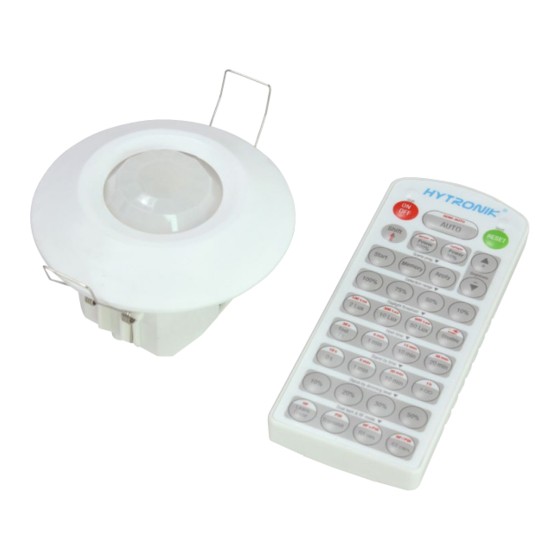
Flush Mount PIR Motion Sensor
HIR24
Tri-level Control for Independent DALI
Mechanical Structure
70mm
4
3
1
Infrared receiver
Rotary switch preset
2
Technical Data
Input Characteristics
Model No.
Operating voltage
Stand-by power
Switched power
Warming-up
Safety and EMC
EMC standard (EMC)
Safety standard (LVD)
Certi cation
www.hytronik.com
PIR
64.7
(1) Sensor inset
(2) Lens pluggable
(3) Protection cover (covers the
Photocell
high-voltage terminals).
LED indicator
(4) Ceiling (drill hole
PIR
Note: the blind can be plugged to the cover for
reducing detection angle if necessary.
HIR24
220~240VAC 50/60Hz
<1W
Max. 20pcs devices, 40mA
30s
EN55015, EN61000
EN60669-1, EN60669-2-1
Semko, CB, CE , EMC, LVD, RCM
Ø
70mm).
Blind
Rotary Switch
Programing
Sensor Data
Model No.
Sensor principle
Detection range
Detection angle
Mounting height
Environment
Operation temperature
IP rating
Intelligent
One-Key
Photocell
Commissioning
Detection Pattern
TX
0
5
Ambient daylight
synchronization
threshold
control
3
HIR24
PIR detection
(O x H) 10m x 3m
360
O
5m (maximum)
Ta: -20
O
C ~ +50
O
C
IP20
IP20
Hytronik PIR motion sensor
362
Advertisement

Related Manuals for Hytronik HIR24


Summary of Contents for Hytronik HIR24
- Page 1 5m (maximum) Environment Safety and EMC Operation temperature Ta: -20 C ~ +50 EMC standard (EMC) EN55015, EN61000 IP rating IP20 Safety standard (LVD) EN60669-1, EN60669-2-1 Certi cation Semko, CB, CE , EMC, LVD, RCM IP20 Hytronik PIR motion sensor www.hytronik.com...
-
Page 2: Functions And Features
ON in the presence, and dims down in the absence, then switches off in the long absence. Note: end-user can choose either function or function for application. Default function is manual override. Hytronik PIR motion sensor www.hytronik.com... - Page 3 Synchronisation Function By connecting the “SYNC” terminals in parallel (see wiring diagram), no matter which sensor detects motion, all HIR24 in the group will turn on the lights when surrounding natural light is below the daylight threshold. The detection area could be widely enlarged in this way.
- Page 4 Note: 1. Make sure the light level measurement covers the night time. 2. The xture will go into sensor mode after the measurement, all sensor settings remain unchanged. Dual tech & RF mode All buttons are disabled. Hytronik PIR motion sensor www.hytronik.com...
- Page 5 HRC-11. The last action controls. 100% 30min 400Lux +∞ 100% 100Lux Wiring Diagram P N L P N L P N L DALI driver DALI driver DALI driver HIR24 HIR24 HIR24 DALI DALI DALI Detection Pattern Hytronik PIR motion sensor www.hytronik.com...
Need help?
Do you have a question about the HIR24 and is the answer not in the manual?
Questions and answers