Bionet BM7Vet Pro Operation Manual
Veterinary patient monitor
Hide thumbs
Also See for BM7Vet Pro:
- Operation manual (226 pages) ,
- Instructions for use manual (215 pages)

Related Manuals for Bionet BM7Vet Pro


Summary of Contents for Bionet BM7Vet Pro
- Page 1 BM7Vet Pro User’s Manual BM7Vet Operation Manual Veterinary Patient Monitor Rev. 3.1 2020.02.06 Warning To ensure proper use of this medical equipment, you must read and comply with this user manual.
- Page 2 Reproduction in any manner, in whole or in part, except for brief excerpts in reviews and scientific papers, is prohibited without prior written permission of Bionet Co., Ltd. Before using Bionet devices, read all the manuals that are provided with your device carefully. Veterinary patient monitoring equipment, however sophisticated, should never be used as a substitute for the human care, attention, and critical judgement that only trained health care professionals can provide.
-
Page 3: Table Of Contents
BM7Vet Pro User’s Manual Table of Contents CONTENTS Intended Use ............................... 9 General Description ............................9 Animal Classification ............................ 10 Functional Safety ............................10 Warning, Caution, Note ..........................11 Define Groups ..............................12 General Precaution On Environment ....................13 Electromagnetic Compatibility ....................... 14 1. - Page 4 BM7Vet Pro User’s Manual 3. Network ................................42 Overview ................................ 42 Network connection ..........................42 IT Network connection .......................... 43 LAN Network ............................... 43 VLAN Network ............................44 If you use an inappropriate network ..................... 44 Display Mode .............................. 46 4.
- Page 5 BM7Vet Pro User’s Manual ECG Precaution ............................65 Animal Preparation ..........................68 ECG Lead ................................ 69 ECG Signal Processing and Display ....................71 ST Signal Processing and Display ....................71 Alarm and Alarm Status ........................72 Display ................................72 ECG Settings ..............................72 Trouble shooting ............................
- Page 6 Sampling method ........................... 111 Display................................112 EtCO Setup ..............................113 Status Message ............................117 14. Temperature ............................120 Overview ..............................120 Display................................121 Temperature Settings ........................... 122 15. Multi-Gas Monitoring ........................123 Overview ..............................123 BMGA(Bionet Multi-Gas Analyzer, Bionet) ................132 Display................................146...
- Page 7 BM7Vet Pro User’s Manual Multi-gas Settings ..........................147 Multi-gas Maintenance ........................150 16. Dual-Gas Monitoring ......................... 155 Overview ..............................155 Display................................159 Multi-gas Settings ..........................160 17. Printer ................................ 163 Overview ..............................163 Printer settings ............................164 Thermal Paper Storage ........................165 Paper Change ............................
- Page 8 BM7Vet Pro User’s Manual Monitor and Peripherals ........................174 20. Technical Specification ........................178 Overview ..............................178 EMC Compatibility (EMC) ........................178 Manufacturer’s declaration - electromagnetic immunity ..........180 Guidance and manufacturer’s declaration - electromagnetic immunity ....186 System Specification ..........................188 Product Configuration..........................
-
Page 9: Intended Use
BM7Vet Pro User’s Manual Intended Use The BM7Vet Pro monitor is for multi-parameter veterinary monitoring. The BM7Vet Pro monitor generates visual and audio alarms when various measured physiological parameters exceed preset limits and times. This equipment is connected to the BM Vet Central System (BT-Link, B-Link). -
Page 10: Animal Classification
Animal Classification BM7Vet Pro monitors are designed for use on animals. At this time, ST segment analysis and arrhythmia should be used for veterinary only. Functional Safety... -
Page 11: Warning, Caution, Note
BM7Vet Pro User’s Manual Warning, Caution, Note The following terms are defined in the User Guide to emphasize the agreement as follows: The user must follow all warnings and precautions. The specifications and functions shown in this manual are subject to change without prior notice. -
Page 12: Define Groups
BM7Vet Pro User’s Manual Define Groups The defined groups for this product are users, service personnel, and experts. Defined groups should read the user manual before using the product and be trained in the use, installation, reprocessing, maintenance and repair of the product. -
Page 13: General Precaution On Environment
BM7Vet Pro User’s Manual General Precaution On Environment Do not keep or operate the equipment in the environment listed below. Avoid placing in an area exposed to moisture. Avoid exposure to Do not touch the direct sunlight equipment with wet hands. -
Page 14: Electromagnetic Compatibility
EMI from external sources. To reduce possible problems caused by electromagnetic interference, we recommend the following: Use only Bionet approved accessories. Otherwise, this equipment may not work ⚫ correctly. Ensure that other products used in areas where veterinary patient monitoring ⚫... -
Page 15: Basic
Please check the following before using the product. 1. Be sure that AC power supply line is appropriate to use. (AC100 - 240V) 2. Be sure that the power source is the one supplied from Bionet. (DC18V, 2.8A, BPM050S18F02 Made by BridgePower Co., Ltd.) 3. - Page 16 BM7Vet Pro User’s Manual Caution The Equipment should be placed far from generator, X-ray equipment, broadcasting equipment or transmitting wires, so as to prevent electrical noises from being generated during the operation, When these devices are near the Equipment, it can produce inaccurate measurements.
-
Page 17: Biocompatibility
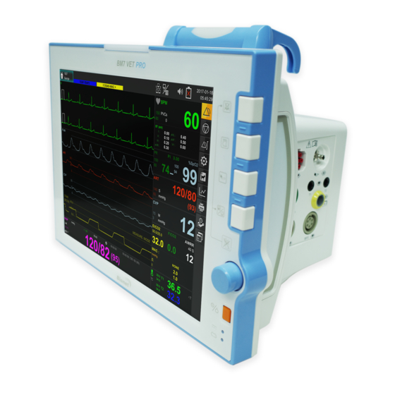
If you have questions about this matter, please contact Bionet or its representatives. Product Configuration 1. Main body of BM7 Vet Pro Monitor 2. -
Page 18: Optional Products
18. Sidestream Multigas Nomo Extension 19. Sidestream Multigas T-Adapter 20. Mainstream Multigas IRMA Airway Adapter (Large/ Medium) 21. Mainstream Multigas IRMA Airway Adapter (Small) 22. Bionet Dual Gas Module Set 23. Water Trap 24. Sample Line Luer Lock (8”) 25. Airway Adapter (Straight) - Page 19 Warning In order to avoid electrical shock, do not open the cover. Disassembling of the equipment should be done only by the service personnel authorized by Bionet. Warning Users must pay attention on connection any auxiliary device via LAN port or nurse calling.
-
Page 20: Basic Unit
BM7Vet Pro User’s Manual Basic Unit Alarm lamp handle Alarm control key Printer key Blood-pressure measurement key Home key Rotary knob key Power ON/OFF Key Battery status indicator Front alarm lamp... - Page 21 BM7Vet Pro User’s Manual ECG connector Blood pressure hose connector connector Temperature connector EtCO connector IBP connector (IBP 3 & 4 not included in USA Model)
- Page 22 BM7Vet Pro User’s Manual Printer USB / SD CARD slot connector (USB 2.0 5Vdc / Max. 500mA) Extended battery connector...
- Page 23 BM7Vet Pro User’s Manual Potential equivalent NURSE CALL connector USB connector (USB 2.0 5Vdc / Max. 500mA) DC input Service Port connector Network connector Video output (HDMI)
- Page 24 BM7Vet Pro User’s Manual Warning USB Compatibility The BM7Vet Pro is compatible with external USB memory drives up to 64GB. ⚫ We recommend products by the following brands: San Disk, PNY, Transcend, ⚫ Samsung. When using a product with high power consumption, such as an external hard ⚫...
-
Page 25: Device Markings
BM7Vet Pro User’s Manual Device Markings Caution :Consult accompanying Ground terminal documents TYPE CF APPLIED PART TYPE BF APPLIED PART Printer Auxiliary Port LAN port HDMI HDMI external port DC Input Indicator USB port Battery Operation indicator DC input connector... -
Page 26: Power
BM7Vet Pro User’s Manual Power The BM7Vet Pro monitor uses a DC adapter (100-240 VAC / 18VDC 2.8A). In the event of a power outage or cable shortage, the monitor automatically switches to battery power to continue veterinary patient monitoring without data loss. - Page 27 BM7Vet Pro User’s Manual (5% -> 25% -> 50% -> 75% -> 100%) 4. When discharging, the battery image is displayed in Red. Battery Type: BM7_ICR18650 22F-032PpTC(10.8V/ 4300mA, Li-ion) or 6BL335-BIO-S(10.8V/6700mA, Li-ion) The Lithium-Ion battery is a rechargeable battery containing Lithium-Ion cells. Each battery contains an integrated electronic fuel gauge and a safety protection circuit.
- Page 28 To maximize the charge for transport, keep the monitor connected until you are ⚫ ready to transport the animal. Reconnect the monitor immediately after transport. Bionet recommends replacing the lithium-ion battery after 24 months of use. ⚫ Battery life depends on usage. If battery life continues, battery life will decrease ⚫...
- Page 29 Warning Be careful of the polarity when replacing the battery. We strongly recommend that you use the battery supplied by BIONET. Using unauthorized batteries may damage the equipment. 5. Presence of battery: When the battery is disconnected from the equipment and it malfunctions, it displays an 'X' as shown below.
-
Page 30: How To Replace The Battery
BM7Vet Pro User’s Manual How To Replace The Battery Please assemble and replace as shown below. The Extra Lithium-Ion Battery Information and How to replace An additional battery module is available as an option, as shown below for extended battery life. - Page 31 BM7Vet Pro User’s Manual 1. Open the battery cover screws using (+) 2. While pressing the battery cover, slide back screwdriver on the left side of BM7 Vet Pro and open cover. 3. Connect the connector located on the inside 4.
- Page 32 12 months. Bionet recommends that you remove the battery and store it near the monitor until it is needed for transport.
-
Page 33: Getting Started
BM7Vet Pro User’s Manual Getting Started Starting the monitor: Press the power key (O) at the bottom right of the monitor front panel. The power light on the monitor lights up, the alarm bar lights up, the screen lights up, and the main screen is displayed after running the self-test. - Page 34 BM7Vet Pro User’s Manual the upper left corner of the screen. The top right of the screen displays the time, network, and device management status. Using Rotary Knob Switch The rotary knob switch allows the user to navigate menus, select settings, and perform menu functions.
- Page 35 BM7Vet Pro User’s Manual Function Key On the right side of the monitor's front panel, the touch screen icon on the touch screen allows you to perform frequently used functions. Fixed key Description Fixed key Description Opens a table where you can...
-
Page 36: Setup
BM7Vet Pro User’s Manual 2. Setup Overview This chapter describes how to configure your monitor and how to upgrade your software. Monitor Configuration Setup Menu Tree Parameter Menu Tree... -
Page 37: Main Menu Setup
BM7Vet Pro User’s Manual Main menu setup The Setup menu allows the user to access submenus, display screens, and perform specific monitor setup functions. 1. To display the Settings menu, click the Settings icon to open the submenu. 2. Click the desired setting to access the submenu that performs the desired function or goes one step further down. - Page 38 BM7Vet Pro User’s Manual A-2-5. Gas Pressure Unit Gas measurement unit mmHg kPa, vol% A-2-6. USE ONE GAS UNIT select whether to set the ON/OFF pressure unit for each gas type. When ON, the unit setting menu for each gas type is displayed.
- Page 39 BM7Vet Pro User’s Manual A-5-5. Gateway IP GATEWAY setting menu XXX.XXX.XXX.XXX A-5-6. Network Interface A-6. Export BM Vet Central Setup Menu (BT-LINK &B-LINK) A-6-1. BT-LINK Protocol Version Network protocol menu 1.3.0 Remote Communication A-6-2. BT-LINK Transmission ON/OFF menu A-6-3. BT-LINK Host IP Remote phone &...
- Page 40 BM7Vet Pro User’s Manual A-10-2. Address 1 Address information 1 A-10-3. Address 2 Address information 2 A-10-4. Postal Code Set postal Code A-10-5. Doctor Name Set Doctor Name B. Biosignal Calibration Set calibration menu B-1. ECG & RESP B-1-1. ECG Calibration...
- Page 41 BM7Vet Pro User’s Manual Parameter Color Parameter Basic color Selectable colors Green, light blue, yellow, magenta, blue, sky blue, gray, white, scarlet, purple, pale green, orange, pink, pale yellow ECG (ST) Green Light Blue RESP Yellow NIBP Magenta TEMP Green...
-
Page 42: Network
BM7Vet Pro User’s Manual 3. Network Overview When you connect the monitor to the network, you can access animal information from another monitor or central station connected to the network. These devices provide main screen information for remote viewing from each other. -
Page 43: Network Connection
BM7Vet Pro User’s Manual and appropriate action must be taken. Subsequent changes to the network example: Network configuration change Removing a device from the network Adding new devices to the network Upgrading or updating devices connected to the network Warning... -
Page 44: Vlan Network
BM7Vet Pro User’s Manual configured on the network switch. Bionet equipment must be configured to make the network settings compatible with the specifications of the operating organization. This device exchanges data with other medical devices over a LAN network. The network supports... - Page 45 BM7Vet Pro User’s Manual Overloading this unit due to very high network loading (e.g. denial of service attacks) can cause interface deactivation. The interface can only be used again after the device is restarted. Rarely, booting may be slow or repeated reboots may occur Remote View—B2B...
-
Page 46: Display Mode
BM7Vet Pro User’s Manual CONNECT Monitor connection menu for remote connection Display Mode Wave and Numeric Mode Numeric Mode... - Page 47 BM7Vet Pro User’s Manual MENU Description Available settings A-1 SELECT WAVE Waveform selection menu The waveform selection menu for ECG, SPO2, IBP1, IBP2, A-1-1. TRACE I TRACE I in the B2B View window RESP, ETCO2, MULTIGAS The waveform selection menu for ECG, SPO2, IBP1, IBP2, A-1-2.
-
Page 48: Animal Information
BM7Vet Pro User’s Manual 4. Animal Information Overview The Animal Inpatient Menu allows the user to enter and edit individual animal information (ID, Animal and Guardian Name, Animal Type, Gender, Weight). You can hospitalize animals on a monitor, or you can be hospitalized on a central station where your monitor is networked. - Page 49 BM7Vet Pro User’s Manual How to discharge an animal. Press the animal icon button. 2. Press Discharge. 2. Check a discharge confirmation message. 3. Press the Yes button. The discharge process is in progress. The monitor displays a Discharge message and a Discharge image in the upper left corner.
- Page 50 BM7Vet Pro User’s Manual Registration of Animal ID Using Barcode This product can input the ANIMAL ID in barcode format to the device using USB barcode scanner. First, connect the barcode scanner to the USB HOST connector on the left as shown in the figure below.
-
Page 51: Alarm
BM7Vet Pro User’s Manual 5. Alarm Overview The monitor displays the alarm limit (parameter threshold) and can be configured by the user to raise an alarm if exceeded. Limits are displayed both in the alarm limits table and in the parameter box. - Page 52 BM7Vet Pro User’s Manual Alarm Priority Alarm Sound Alarm Color Alarm Printer Front Alarm Handle Alarm Lamp Lamp HIGH Every 2 2 times 2 times seconds Blinking a Blinking a Blinking second second MEDIUM Every 2 Every 2 seconds seconds...
- Page 53 BM7Vet Pro User’s Manual Alarm management You can use the lock key on the front of the monitor to hold the alarm. To change Alarm Mode: A short press of the alarm control key circulates through the Normal / Audio_Paused / Alarm_Paused alarm modes. Press and hold the key for more than 3 seconds to...
-
Page 54: Alarm Settings
BM7Vet Pro User’s Manual Note Audio Paused and Audio Off modes only stop the audible alarm sound and touch or key ⚫ sound is activated always. To adjust the Touch or Key Sound, use the Key Sound menu in Setup. -
Page 55: Alarm Event (Physiological Alarm Review)
BM7Vet Pro User’s Manual One time A-5-3. Duration Nurse call duration setup menu Continue Cycling A-5-4. Level Alarm level setup menu Low / Medium / High Alarm Event (Physiological Alarm Review) -
Page 56: Trend
BM7Vet Pro User’s Manual 6. Trend Overview The monitor stores trend data for all connected signals. Users can request trend recording and can also print the screen of trends displayed. The triggered alarm event is displayed in red inverted triangle on the Event List and Timeline. - Page 57 BM7Vet Pro User’s Manual B-1-3. Display Group Configure the bio signal to be shown in Graphic trend window B-1-4. Print Graphic trend print output C. Tabular Trend menu C-1. Tabular Trend C-1-1. Event List Selectable alarm list is displayed C-1-2. Time Period...
-
Page 58: Graphical Trend
BM7Vet Pro User’s Manual Graphical Trend Trend graph shows saved trend data as individual graph type for each parameter. These graphs show that the displayed parameters are active over a significant period of time and can display up to five channels at a time. Confirmation color, scale meter labels and numbers are displayed on the left side of the trend channel. -
Page 59: Tabular Trend
BM7Vet Pro User’s Manual ⑧ Trend interval setting menu ⑨ Parameter selection slider ⑩ Printer menu ⑪ Parameter window selection menu Tabular Trend The Trends table displays the trend data in an easy-to-read table format. Up to six are displayed, updated every minute. -
Page 60: File Export
BM7Vet Pro User’s Manual Event previous/next menu ④ Animal ID ⑤ ⑥ Numeric Parameter window ⑦ Selection Navigation window ⑧ Trend interval setting menu Parameter selection slider ⑨ Printer menu ⑩ Parameter window selection menu ⑪ File Export The file export function can transfer trend data to a file using USB memory. - Page 61 BM7Vet Pro User’s Manual Warning USB Compatibility ⚫ The BM7Vet Pro is compatible with external USB memory drives up to 64GB. ⚫ We recommend products by the following brands: San Disk, PNY, Transcend, Samsung. ⚫ When using a product with high power consumption, such as an external hard drive, be sure to use the provided adapter for suitable power supply.
-
Page 62: Pop-Up Trend
BM7Vet Pro User’s Manual Pop-up Trend The user can continue to monitor the main screen waveform and parameter box while displaying trend data for up to 7 parameters for up to 6 hours. The pop-up Trend Graph follows the display order indicated by each parameter in the Trend Setup and is updated with new trend data every 60 seconds. - Page 63 BM7Vet Pro User’s Manual Pop-up ST Window Pop-up Enlarge Trend Window You can change the size of the popup menu by pressing and releasing the center of the popup menu for at least 1 second.
-
Page 64: Ecg
BM7Vet Pro User’s Manual 7. ECG Overview The monitor can calculate heart rate, detect arrhythmia, and display ECG data. The electrocardiogram screen provides 1 channel, 2 channel, and 7 channel displays. It calculates the heart rate by detecting the electrocardiogram signal of the animal and alarms according to the set upper and lower limit of the alarm. -
Page 65: Ecg Precaution
BM7Vet Pro User’s Manual Note Make sure that the contact area of the disposable electrode is not dry to maintain a ⚫ good connection between the electrode and the skin. If you suspect that the disposable electrode is in poor contact, replace it immediately ⚫... - Page 66 BM7Vet Pro User’s Manual of the neutral electrode and ground. DEFIBRILLATION — Do not come into contact with animals during defibrillation. Otherwise serious injury or death could result. To avoid the risk of serious electrical burn, shock, or other injury during defibrillation, all persons must keep clear of the bed and must not touch the animal or any equipment connected to the animal.
- Page 67 BM7Vet Pro User’s Manual ESU, RF interference may affect the monitor operation. Locate the monitor as far as possible from the ESU. Locate them on opposite sides of ✓ the operating table, if possible. Connect the monitor and ESU to different AC outlets located as far as possible from ✓...
-
Page 68: Animal Preparation
There are a variety of reusable and disposable electrodes available. Choose the electrode that best fits your monitoring situation. Bionet recommends Ag / AgCl disposable electrodes. If you are using an electrode with a gel beforehand, make sure that the electrode is sufficiently gelled. -
Page 69: Ecg Lead
BM7Vet Pro User’s Manual ECG Lead 5 Positions of 5 Lead Placement... - Page 70 BM7Vet Pro User’s Manual 3 Positions of 3 Lead Placement ECG Cable color AHA:American Heart Association (U.S.A.) IEC:International Electrotechnical Commission (Europe) 3LEAD / 5LEAD Lead wire Color code Label Color code Label Right arm White Left arm Black Yellow Right leg...
-
Page 71: Ecg Signal Processing And Display
BM7Vet Pro User’s Manual ECG Signal Processing and Display The monitor displays QRS Complex for an amplitude of 0.4 to 5.0 mV (0.2 -5.0 mV for scale settings below 0.5 mV / cm) and a QRS width of 70 to 120 ms for large animals (also for small animals with 40 to 100 ms). -
Page 72: Alarm And Alarm Status
BM7Vet Pro User’s Manual Alarm and Alarm Status High P-wave and T-wave, Long P-wave or T-wave with high amplitude duration can be detected by QRS Complex. Place the leads on the ECG1 channel with the highest R-wave (compare to T- wave and / or P-wave) to allow the monitor to properly detect low heart rate conditions in this situation. - Page 73 BM7Vet Pro User’s Manual A. ECG menu MENU Description Available settings A-1. Alarm ECG alarm setting menu A-1-1. PARAMETER ALARM HR, ST, PVC parameter alarm limits, LIMIT level, activation setup menu. A-1-2. TECHNICAL ALARM ECG-CABLEOFF CONDITION ECG-LEADFAULT ECG-CHECKELECTRODE ECG-HR-SEARCH A-2.
- Page 74 BM7Vet Pro User’s Manual When selecting 1CH, ECG waveform of 1CH is displayed in two lines. 3LEAD: Only 1CH is displayed 5LEAD: 1CH, 2CH, 7CH display The ECG channel is selectable from I to I, II, III, aVR, aVL, aVF, When using the 3 lead cable selection, A-3-6.
-
Page 75: Trouble Shooting
BM7Vet Pro User’s Manual Trouble shooting Problem: Inaccurate heart rate and/or false asystole. Solution: Check ECG signal from patient: 1. Check and adjust the electrode placement. 2. Check the electrode attachment to the skin and attach it correctly. 3. Check the condition of the electrode and replace it if necessary. - Page 76 BM7Vet Pro User’s Manual Problem: Inaccurate pacemaker detection Solution: Use pacemaker processing: 1. Select ECG parameter label. 2. Display the lead of ECG with the greatest amplitude in the top waveform position. 3. Select Pace Maker. 4. SELECT PACE MAKER ON.
-
Page 77: Arrhythmia Monitoring
BM7Vet Pro User’s Manual 8. Arrhythmia Monitoring Overview Arrhythmia monitoring is available for animals only. The selected mode (Full, Lethal or OFF) determines which events are processed. The monitor compares the received beats to the reference beats that have been recorded and stored in the reference template. Through this process, the monitor can identify the occurrence of an arrhythmia event, classify it, and then draw clinically useful conclusions based on the frequency and type of the signal. -
Page 78: Arrhythmia Settings
BM7Vet Pro User’s Manual detected and has non-ventricular beats before and after. R ON T: Occurs when a ventricular complex is detected within the repolarization period of a non- ventricular beat. TRIGEMINY: Occurs when two or more trigeminal cycles (a ventricular beat followed by two non- ventricular beats) are detected. - Page 79 BM7Vet Pro User’s Manual Warning Display Heart Beat Equipment Signal Heart Beat equipment signal displays when the PACE mode is. the signal appears series form. The signal size or form are meaningless clinically Number Of Heart Beat Attention to the animal with heart beat equipment. The heart beat equipment can show heart beat even during arrhythmia continuously.
-
Page 80: Spo
The accuracy of SpO2 monitoring is largely dependent on the strength and quality of the SpO2 signal. Install a sensor at the tip of the animal's tongue for the SpO2 measurement. Only use sensors provided by Bionet and apply them according to manufacturer's recommendations on a per-sensor basis. - Page 81 BM7Vet Pro User’s Manual with the opaque body is covered. 1. Select the sensor type and size that best suits your animal. 2. If the sensor can be reused, please wash it before use for each animal. 3. Position the sensor correctly and attach it to the animal.
-
Page 82: Display
BM7Vet Pro User’s Manual Note The signal input is a high-insulation port and it is defibrillator proof. The insulated input ensures animal safety and protects the device during defibrillation and electro surgery. Display ② ① ③ ④ ⑤ ⑥ SpO2 pulse rate display ①... - Page 83 BM7Vet Pro User’s Manual Note WAVE SIZE changes automatically. Signal and Data Validity It is extremely important to determine that the probe is attached to the animal correctly and the data is verifiable. To make this determination, three indications from the monitor are of assistance—signal strength bar, quality of the SPO...
- Page 84 BM7Vet Pro User’s Manual Waveform with Artifact Stability of SPO Values The stability of the displayed SPO values can also be used as an indication of signal validity. Messages are provided in the SPO values window to aid you in successful SPO monitoring.
-
Page 85: Spo 2 Settings
BM7Vet Pro User’s Manual Settings A. SPO menu MENU Description Available Settings A-1. Alarm Alarm setup menu A-1-1. PARAMETER ALARM PERCENT, PR parameter alarm , level , LIMIT activate setup menu A-1-2.TECHNICAL ALARM SPO2-PROBEOFF CONDITION SPO2-CHECKPROBE SPO2-POORSIGNAL SPO2-LOSTPULSE SPO2-ARTIFACT SPO2-PULSESEARCH A-2. - Page 86 BM7Vet Pro User’s Manual Detection by the monitor of a repeatable pulse has ceased. Check the animal and the probe site. POOR SIGNAL The SPO signal is too low and no SPO data is displayed. This can be due to a low veterinary animal pulse, animal motion, or some other interference.
-
Page 87: Respiration
Impedance breath monitoring should not be considered the only way to detect a stop in ⚫ breathing. Bionet recommends monitoring of additional parameters, such as EtCO , that indicates the animal's oxygen supply status. If you use an ESU block or cable, the impedance breathing monitor may not function and ⚫... - Page 88 BM7Vet Pro User’s Manual Respiration Connector and Measurement Cable Respiration connector Respiration cable Note Respiration Rate measured by the cable and connector will be used as the ECG and common.
-
Page 89: Display
BM7Vet Pro User’s Manual Display ① ② ③ ④ Breath indicator: Indicates the detected breath ① Breathing number: Displays the number of respirations per minute ② Respiration alarm limit: Indicates respiration limits ③ Apnea Limit Setting: Apnea limit sign ④... - Page 90 BM7Vet Pro User’s Manual A-2-1. Sweep Speed A menu to setup Wave Display of 6.25mm/s, speed 12.5mm/s, 25mm/s, A-2-2. Size A menu to setup Wave Display 2, 4, 6, 8, 10 A-2-3. Lead Select This is for changing the reference...
-
Page 91: Nibp
BM7Vet Pro User’s Manual 11. NIBP Overview The monitor can acquire and process non-invasive blood pressure (NIBP) signals and display the numerical values. NIBP can also be used during electrosurgery Blood pressure measurements are determined by the oscillometric method and are equivalent to... - Page 92 BM7Vet Pro User’s Manual Cuff (For USA Only) POSITION OF CUFF (DOG) The hose should line up with the vessel that trying measure. When using a leg, this is on the underside (backside) of the leg. Note: The cuff must be at the same level as the patient’s heart for best...
-
Page 93: Display
BM7Vet Pro User’s Manual Note As the value of NIBP can vary according to the age and sex of an animal, the user needs to set correct data in the Parameter Menu before measurement. Display ① ② ③ ④ ⑤... -
Page 94: Nibp Settings
BM7Vet Pro User’s Manual NIBP Settings A. NIBP menu Menu Description Available Settings A-1. Alarm NIBP Alarm setup menu A-1-1. Parameter Alarm Limit SYS, MEAN, DIA Parameter alarm limit, level, activation setup A-1-2. TECHNICAL ALARM NIBP-OVER PRESSURE CONDITION NIBP-OVERTIME PRESSURE... - Page 95 BM7Vet Pro User’s Manual SMALL: 60-140mmHg MEDIUM: 80- 140mmHg LARGE: 120-250mmHg A-4. SETTING TIME How to apply pressure value setting. Once, Once: When the blood pressure is Every Time measured for the first time, the pressure is set to the set pressure...
-
Page 96: Safety Considerations
The quality of NIBP monitoring depends largely on the quality of the signals received by the monitor. For this reason, it is important to select the correct cuff size for your animal. Cuff sizes are clearly marked on the cuff. Measure the circumference of your animal’s limb. Use only Bionet provided cuffs with your monitor. -
Page 97: Status Messages
BM7Vet Pro User’s Manual Status Messages An error message is displayed in the following situations If the cuff hose is not connected properly → INFLATION FAILURE CHECK CUFF When the cuff pressure is excessive → OVER PRESSURE When the cuff breaks and cannot exhaust →... -
Page 98: Invasive Blood Pressure
BM7Vet Pro User’s Manual 12. Invasive Blood Pressure Overview IBP has an alarm function based on the maximum & minimum alarm values configured by measuring the systolic, diastolic and mean blood pressure values with signal processing of electric signals which are transformed from changes in impedance components according to the changes of blood flow in vessels. - Page 99 BM7Vet Pro User’s Manual IBP CONNECTOR Reusable Pressure Transducers Cartridges and Monitoring kit Model number Description MX9604A Logical® 60°(152㎝) single monitoring kit MX9602A Logical® double monitoring kit MX960 Logical® transducer mounting plate...
- Page 100 BM7Vet Pro User’s Manual MX261 Logical® clamp for transducer bracket MX262 Logical® bracket for two transducer mounting plates Disposable Pressure Transducers Cartridges and Monitoring kit Model number Description MX9504T TranStar® 60° single line monitoring kit...
- Page 101 BM7Vet Pro User’s Manual MX800 Modular transducer mounting plate MX240 Pole clamp for mounting a transducer plate MX4810 C-fuser® 1000ml Pressure Infuser complete unit with squeeze bulb and pressure gauge...
-
Page 102: Precautions
BM7Vet Pro User’s Manual Precautions The following precautions apply to IBP procedures. See the hospital's clinical guidelines for details. Warning All parts, except the Transducer, should not be conductive. Otherwise, discharge ⚫ energy may induce a shock to operators during cardioversion. -
Page 103: Display
BM7Vet Pro User’s Manual Display ① ② ③ ⑦ ④ ⑤ ⑥ ① ② ⑤ ⑥ ① Measuring Position: Position of blood pressure measurement ② Systolic Blood Pressure: Indicating maximum blood pressure value ③ Diastolic Blood Pressure: Indicating minimum blood pressure value ④... -
Page 104: Ibp Settings
BM7Vet Pro User’s Manual IBP Settings A. IBP menu Menu Description Available settings A-1. Alarm IBP Alarm settings menu A-1-1. Parameter Alarm Limit IBP-SYS, MEAN, DIA, PR parameter alarm, level, activate setup A-2. BP Filter Menu to set the filter to be applied... - Page 105 BM7Vet Pro User’s Manual 1) Close the transducer stopcock on the animal’s side. 2) Open the venting stopcock on the air side. 3) Press the knob switch on the monitor panel. 4) Draw a line with the current input data in IBP area of WAVE WINDOW according to the Wave Base Line.
-
Page 106: Etco
BM7Vet Pro User’s Manual 13. EtCO Overview The BM Series monitor measures concentrations of end-tidal CO (EtCO ) when this option is enabled and the EtCO module is connected to your monitor. The EtCO module can perform mainstream measurements in all monitoring modes and as well as... - Page 107 BM7Vet Pro User’s Manual Sidestream EtCO Accessories Intubation accessories Airway Adapter Kit w/ Intended for use when Dehumidification monitoring Large animals 3473ADU-00 Tubing (Cat / Dog / Horse) with ETTube sizes > 4.0 mm Airway Adapter Kit w/ Intended for use when...
- Page 108 BM7Vet Pro User’s Manual EtCO Placements and Accessories (Mainstream, Respironics) EtCO connector CAPNOSTAT 5 mainstream CO sensor and connector Mainstream connector Mainstream sensor...
- Page 109 BM7Vet Pro User’s Manual Mainstream EtCO Accessories Intubation animal Airway adaptor Model Picture Description Large animals (Cat / Dog / Horse) 6063-00 (Disposable) Small animals (Puppy) 6312-00 (Disposable)
-
Page 110: Precaution
BM7Vet Pro User’s Manual Precaution Warning Animal monitors that measure CO , anesthetics, and/or respiratory mechanics ⚫ cannot be used as apnea monitoring and/or recording equipment. While these products provide an apnea alarm, the alarm condition begins with the elapsed time from when the last breath was detected. -
Page 111: Sampling Method
BM7Vet Pro User’s Manual Sampling method Connecting the CAPNOSTAT® 5 CO Sensor to the Host System 1. Insert the CAPNOSTAT 5 CO Sensor connector into the receptacle of the host monitor as shown in Figure 1. 2. Make sure the arrows on the connector are at the top of the connector and line up the two keys of the connector with the receptacle and insert. -
Page 112: Display
BM7Vet Pro User’s Manual How to connect a sidestream accessory: 1. The sample cell of the sampling kit must be inserted into the sample cell receptacle of the LoFlo CO Module as shown in Figure 1. A “click” will be heard when the sample cell is properly inserted. -
Page 113: Etco 2 Setup
BM7Vet Pro User’s Manual EtCO concentration alarm upper and lower limit value display ① Apnea alarm set time in seconds ② Display CO concentration value at exhalation ③ Display the carbon dioxide concentration value at inhalation ④ Show respiratory rate per minute ⑤... - Page 114 BM7Vet Pro User’s Manual A-2-1. SWEEP SPEED Waveform sweep speed setup 6.25mm/s, 12.5mm/s, 25mm/s A-2-2. SCALE Display waveform scale setup. 40mmHg(5.3vol%) The selectable value is the maximum 50mmHg(6.6 vol%) pressure range shown in the waveform. 60mmHg(7.9 vol%) When you select a range value, the 80mmHg(10.5 vol%)
- Page 115 BM7Vet Pro User’s Manual with the sensor in service since the last zero. A-4-7. PUMP TOTAL TIME This is the total time the pump has Min. display been on. (LoFlo only) A-4-8. PUMP MAX TIME This value indicates the maximum Min.
- Page 116 BM7Vet Pro User’s Manual A-5-5. GAS TEMPERATURE This setting is used to set temperature 35.0 °C of the gas mixture. This setting is useful when bench testing using static gasses where the temperature is often room temperature or below. A-5-6.
-
Page 117: Status Message
BM7Vet Pro User’s Manual 40seconds. The typical time for a zero is 15~20seconds. C-1. MODULE RESET EtCO MODULE initializing. Note For best result, connect the CAPNOSTAT 5 CO Sensor to an adapter and wait 2 minutes before performing the Adapter Zero procedure. - Page 118 BM7Vet Pro User’s Manual - Cause: Zero Required, Zero Error - Solution: To clear, check airway adapter and clean if necessary. If this does not correct the error, perform an adapter zero. If you must zero more than once, a possible hardware error may exist.
- Page 119 BM7Vet Pro User’s Manual EtCO measurement failure EtCO value is not output, or numerical error. Troubleshoot procedure 1. Check the connection between the main unit and the module 2. Check the module line connection with the filter line or airway 3.
-
Page 120: Temperature
BM7Vet Pro User’s Manual 14. Temperature Overview This function is used to indicate the changes of resistance generated by the changes of temperature in numbers. The function involves the process of translating the changes into electric signals. Temperature Connector and Measuring Cable... -
Page 121: Display
BM7Vet Pro User’s Manual Warning The temperature sensor must be connected in the correct position and secured so as not to be separated from the animal. The temperature cable should be attached to the monitor. Note The minimum measuring time required to obtain accurate readings at the specific body site is at least 3 minutes. -
Page 122: Temperature Settings
BM7Vet Pro User’s Manual Temperature difference value display ③ Temperature unit display ④ Temperature Settings A. Temp menu MENU Description Available Settings A-1. Alarm Temp Alarm Settings menu A-1-1. PARAMETER ALARM TEMP1, TEMP2, DELTA TEMP Parameter LIMIT Alarm level, Action setup menu Settings range from 0℃... -
Page 123: Multi-Gas Monitoring
Enflurane, Sevoflurane and Desflurane) as well as O2 concentration (optional) in respiratory gases. All measured values as well as derived values are passed to the monitor. BIONET offers the following Multi(Dual)-Gas modules. ISA Mainstream Analyzer (Masimo) ⚫ ISA Sidestream Analyzer (Masimo) ⚫... - Page 124 BM7Vet Pro User’s Manual Accessory ISA Analyzers Product Description Catalog ISA CO 800101 ISA CO Module 700101 ISA AX+ O, 5 AA, AA ID 800601 ISA AX+ Module O, 5 AA, AA ID 700601 ISA OR+ O, 5 AA, AA ID...
- Page 125 BM7Vet Pro User’s Manual (thus requires no calibration after assembly) Tubing, Y-connector and cable for connection between the Pm1116 and ISA AX+ Module. ISA OR+ Sprint Module Includes the following: 700402 One 700601 ISA AX+ Module One 100836 Servomex Paracube Sprint O...
- Page 126 BM7Vet Pro User’s Manual T-adapter, Box of 25 Straight airway adapter with female luer lock connector. 108250 Single animal use. Connects to Nomoline and Nomo Extension. Accessories Product Description Catalog ISA Analyzer Clamp Adapter Adapter for mounting a “plug-in and measure”...
- Page 127 BM7Vet Pro User’s Manual To connect the reference gas inlet fitting to the ISA build-in module, "ISA Module Tubing" 100801 could be used. ISA Reference Gas Inlet Comes in pack of 25. For ISA built-in modules 100805 only. The filter should be used in combination Filter with the “ISA Reference Gas Inlet Fitting”...
- Page 128 BM7Vet Pro User’s Manual The ISA sidestream analyzers are available as stand-alone “plug-in and measure” analyzers or build-in modules. ISA CO The ISA CO analyzers are low flow sidestream gas analyzers, designed for routine clinical use in environments that place special demands on the product’s ruggedness. Its low power...
- Page 129 BM7Vet Pro User’s Manual The Nomoline Family To overcome the shortfalls of current gas sampling solutions, the Nomoline Family sampling lines have been developed for the ISA sidestream gas analyzers. Unlike traditional solutions that remove water vapor and collect water in a container, the Nomoline Family sampling lines incorporates a unique water separation (no moisture) section, which removes condensed water.
- Page 130 BM7Vet Pro User’s Manual with male Luer Lock connector and the Nomoline Adapter with female Luer Lock connector. The Nomoline Airway Adapter Set with integrated airway adapter can be used with intubated animals. The Nomoline with a male Luer Lock type connector is compatible with any normal configuration that uses a female Luer Lock connector.
- Page 131 BM7Vet Pro User’s Manual Multi-gas connector position and accessory (Mainstream, Masimo Sweden AB) Connector The entire IRMA Mainstream Analyzer, weighing only 25 grams, is as small as a pulse oximeter sensor. It is designed using the latest advances in miniaturized components and microprocessor technology to provide a complete mainstream monitoring system with unique versatility and design.
-
Page 132: Bmga(Bionet Multi-Gas Analyzer, Bionet)
BM7Vet Pro User’s Manual BMGA(Bionet Multi-Gas Analyzer, Bionet) The Binet Multi-Gas Analyzer (BMGA) is a multi-gas analyzer for analyzing respiratory gases during anesthesia and intensive care. Respiratory gases analyzed are carbon dioxide (CO2), nitrous oxide (N2O), and five anesthetic agents (HAL, ENF, ISO, SEV, DES). The BMGA can analyze oxygen (Oxygen: O2) when combined with a compact, low-power, optional electrochemical oxygen sensor. - Page 133 BM7Vet Pro User’s Manual Water Trap Fastening Button: Slide button to fasten the water trap Gas Inlet: A tube into which gas is injected from a sampling line into a multigas analyzer for gas measurement Water Trap: Apparatus for removing moisture that may affect the analysis of respiratory...
- Page 134 BM7Vet Pro User’s Manual Rear view Electro-chemical Oxygen Sensor Cover: Open / close the screw when replacing the oxygen sensor Power Line: A wire to connect power and communication from a host device Electrochemical oxygen sensor. In addition to non-dispersive infrared absorption (NDIR) optical multi-gas measurement, BMGA...
- Page 135 The following points illustrate the electrochemical oxygen sensor technology. The operating principle of oxygen sensor applied to Bionet is galvanic cell method. When oxygen flows from the outside of the sensor to the inside of the sensor, a current that is proportional to the oxygen...
- Page 136 BM7Vet Pro User’s Manual Replace electrochemical oxygen sensor. Assemble and replace as shown below. BMGA Body Electrochemical Oxygen Sensor oxygen sensor cover screws (M3 * 3)
- Page 137 BM7Vet Pro User’s Manual 1. Use a screwdriver to loosen the screw on the 2. Open the cover and there are spaces for oxygen sensor cover on the back of the BMGA. oxygen sensor and oxygen sensor connector. 3. Connect the oxygen sensor after turning it 4.
- Page 138 BM7Vet Pro User’s Manual Water trap Mindray®'s DRYLINE ™ II water trap is a system that protects contaminants, including moisture, from secretions, dust and bacterial contamination from multi-gas analyzers. The system allows you to constantly monitor the state of anesthesia.
- Page 139 BM7Vet Pro User’s Manual Replace water trap information. Assemble and replace as shown below. Water Trap (DRYLINE™ II) Water Trap Coupling (DRYLINE™ II Receptacle)
- Page 140 BM7Vet Pro User’s Manual 2. Attach the water trap to the water trap 1. Prepare the water trap. coupler on the front of the BMGA. 3. Insert the water trap so that the slide button 4. When the slide button is down, the water on the top of the mating portion rises up.
- Page 141 BM7Vet Pro User’s Manual Sample Collection Method. BMGA, a sidestream multigas analyzer, continuously extracts some gas samples from the respiratory circuit, such as the nasal cannula, the respiratory mask, or the Y tube of an intubated animal. Gas samples are supplied via sampling lines.
- Page 142 BM7Vet Pro User’s Manual Gas sampling connection in Y-piece. A gas circuit is constructed by connecting the gas supply line and the Y-type pipe. Fasten the sampling line to the male type connector on the top of the HME unit (head and moisture...
- Page 143 BM7Vet Pro User’s Manual Trouble Shooting and Solutions When the measurement density error is high during operation ① Check the connection of sampling line and water trap and reconnect. ② Check the connection between the water trap and the water trap holder and reconnect them.
- Page 144 BM7Vet Pro User’s Manual General maintenance setup. Install for maintenance as shown below ② Flow meter ④ T-piece ③ Sampling line Water trap ⑤ BMGAPati ⑥ ① Calibration Calibration gases (N2O, O2, CO2, Agents) T-piece Flow meter for 200 ml/min...
- Page 145 BM7Vet Pro User’s Manual Caution The calibration gas must be used in the concentration (%) range shown below Nitrous oxide (N2O)> 30% ◼ Carbon dioxide (CO2)> 2.5% ◼ Oxygen: O2> 40% ◼ Agents> 1% ◼ Caution The calibration gas must use gas with balance N2. (Eg 21% O 2, bal. N 2). After the...
-
Page 146: Display
BM7Vet Pro User’s Manual Display ① ② ③ ④ ⑤ ⑥ ⑦ ⑧ EtCO alarm limits display ① EtCO value display ② FiCO value display ③ Respiration rate value display ④ Apnea alarm setting time in seconds ⑤ Multi-gas unit display ⑥... -
Page 147: Multi-Gas Settings
BM7Vet Pro User’s Manual Multi-gas Settings A. Multi-gas menu Menu Description Available Settings A-1. DUALGAS Parameters A-1-1. ALARM Multi-gas Alarm setting menu A-1-2. PARAMETER ALARM The default setting range of alarm set LIMIT values of EtCO , FiCO , AWRR, APNEA,... - Page 148 BM7Vet Pro User’s Manual menu A-2-1. SWEEP SPEED Sweep speed setup 6.25mm/s, 12.5mm/s, 25mm/s A-2-2. SCALE Waveform display scale setup. 40.0 mmHg (5.3 vol%), 50.0 mmHg The selectable value is the maximum (6.6 vol%), 60.0 pressure range shown in the waveform.
- Page 149 BM7Vet Pro User’s Manual selection A-2-10. N O Unit Displayed when USE ONE GAS UNIT is mmHg/kPa/vol% OFF. N2O gas measurement unit selection A-2-11. O Unit Displayed when USE ONE GAS UNIT is mmHg/kPa/vol% OFF. O2 gas measurement unit selection A-2-12.
-
Page 150: Multi-Gas Maintenance
BM7Vet Pro User’s Manual O2 Sensor type setup menu (default: Galvanic A-4-12. O2 TYPE SERVOMEX) Servomex A-4-13. IR O2 Delay In seconds A-4-14. O2 OPTION O2 function available setup menu ON/OFF A-5. MODULE INFORMATION Module Information Menu A-5-1. SENSOR SN... - Page 151 BM7Vet Pro User’s Manual 4.0 to 11.0 % 30 to 100 % 2.0 to 12.0 % 45 to 100 % Accuracy for all gases: ± 0.03 vol% or ± (0.02 vol% + 0.1% of reading), whichever is greatest. Maintenance tasks PHASEIN Gas Master can be used to complete the maintenance task.
- Page 152 BM7Vet Pro User’s Manual 8. If the cuvette pressure value changes more, troubleshoot tubing and fittings. If the problem persists, return the analyzer to PHASEIN. Note: In step 5, if the cuvette pressure is less than 15 kPa below atmospheric pressure, repeat steps 1 to 3 blocking the exhaust port quicker.
- Page 153 BM7Vet Pro User’s Manual values are set (if applicable for your gas analyzer model) correctly to match the corresponding calibration gas. Span calibration can be performed using gases within the ranges: 4.0% ≤ CO ≤ 11.0% 45% ≤ O ≤ 100% - for ISA Multi-gas with Servomex only 30% ≤...
- Page 154 BM7Vet Pro User’s Manual 7. Verify the gas readings. Note: If the calibration process fails, the flag SPAN_ERR is set, and will stay active until the next successful calibration is passed...
-
Page 155: Dual-Gas Monitoring
All measured values as well as derived values are passed to the Veterinary patient monitor. BIONET offers the following D-GAS modules. BDGA Sidestream Analyzer (Bionet). Dual gas connector position and accessory... - Page 156 BM7Vet Pro User’s Manual Accessories Bionet Dual Gas Module...
- Page 157 BM7Vet Pro User’s Manual The Dual Gas module is a sidestream multi-gas analyzer measuring end-tidal carbon dioxide (EtCO2) and one of five anesthetic agents (isoflurane, sevoflurane, enflurane, halothane and desflurane) with manual selection of the specific agent type. The Dual Gas parameter window shows the concentration of EtCO2 and an anesthetic gas, respiration rate, and MAC (Minimum Alveolar Concentration).
- Page 158 BM7Vet Pro User’s Manual Feature Specification 0 – 100 mmHg; 0 – 13.3 kPa; 0-10% CO2 STPD (standard - Range temperature and pressure dry) - Accuracy ± (0.2 vol% + 4% relative) - Rise Time 400 ms (average) Anesthetic Agents...
-
Page 159: Display
BM7Vet Pro User’s Manual Display ① ② ③④ ⑤ ⑥ ⑦ ⑧ ① EtCO2 alarm high / low limit display EtCO2 Exhales CO2 values. ② FiCO2 Inhalation CO2 value display ③ Display respiratory rate value ④ Apnea alarm Set time in seconds ⑤... -
Page 160: Multi-Gas Settings
BM7Vet Pro User’s Manual Multi-gas Settings A. Multi-gas menu Menu Description Available Settings D-1. Alarm Multi-gas Alarm setting menu D-1-1.PARAMETER ALARM The default setting range of alarm set LIMIT values of EtCO , FiCO , AWRR, APNEA, AG-E, AG-I, N... - Page 161 BM7Vet Pro User’s Manual D-2-1. SWEEP SPEED Sweep speed setup 6.25mm/s, 12.5mm/s, 25mm/s D-2-2. SCALE Waveform display scale setup. 40.0 mmHg (5.3 vol%), 50.0 mmHg The selectable value is the maximum (6.6 vol%), 60.0 pressure range shown in the waveform.
- Page 162 BM7Vet Pro User’s Manual selection D-3. APNEA DETECT Displayed when USE ONE GAS UNIT is mmHg/kPa/vol% OFF. N2O gas measurement unit selection D-4.MODULE SETUP Module Setup Menu D-4-1. AGENT ID1 Primary Agent ID setup D-4-2. GAS MODE Gas status setup...
-
Page 163: Printer
BM7Vet Pro User’s Manual 17. Printer Overview The monitor allows the user to print out monitoring data, including trends and alarm data. Recordings of waveforms are either timed or continuous and print at a recording speed of 25mm/s. All recordings are identified by the animal’s name, ID as well as the date and time of the recording request. -
Page 164: Printer Settings
BM7Vet Pro User’s Manual Printer settings Main menu Sub menu A. Print Setup A-1. Printer Setup Menu Description Available settings A. Print Setup menu A-1. Printer Setup A-1-1. Use Of Printer PRINTER activation menu ON / OFF A-1-2. Printer Speed... -
Page 165: Thermal Paper Storage
BM7Vet Pro User’s Manual Thermal Paper Storage To avoid print quality degradation or attenuation of printouts, follow these precautions: Note These precautions apply to both unused paper as well as paper that has already been run through the printer. • Store in cool, dark locations. Temperature must be below 27°C (80°F). Relative humidity must be between 40% and 65%. -
Page 166: Paper Change
BM7Vet Pro User’s Manual when properly imaged and stored for about 3-5 years. If your retention requirements exceed these guidelines, we recommend you consider alternate image storage techniques. Paper Change Open the window of the printer. Insert the paper roll offered with the product into the printing unit. -
Page 167: Maintenance And Troubleshooting
BM7Vet Pro User’s Manual Maintenance And Troubleshooting Noise in ECG - Make sure your filter settings are appropriate - Make sure the electrode is attached - Make sure the gel on the electrode is not dry. The Patient’s skin Apply ECG gel or water to the area of... -
Page 168: Spo 2 Malfunction
BM7Vet Pro User’s Manual Malfunction - If the connectors of the equipment are in bad condition The extension cables Replace extension cables Are disconnected The finger probe is Replace the finger probe in bad condition? Repair the ECG B/D Temperature malfunction... -
Page 169: Nibp Malfunction
BM7Vet Pro User’s Manual NIBP Malfunction - Confirm that the hose is normally connected Are leaks from the hose Replace the hose of cuff Connector of cuff Repair the NIBP B/D Abnormality In NIBP Measurements Make sure the patient stay... -
Page 170: Multi-Gas & Dual Gas Malfunction
BM7Vet Pro User’s Manual Multi-gas & Dual Gas Malfunction The extension cables Replace extension cables Are disconnected The module is Replace the module in bad condition? Repair the adaptor EtCO Malfunction The extension cables Replace extension cables Are disconnected The module is... -
Page 171: Failure In Battery Recharge
BM7Vet Pro User’s Manual Failure In Battery Recharge (the battery does not fully recharge in 6 hours or more) Replace the adapter The output voltage of (the battery will not be changed the adapter is 18V at the rate lower than 17V) -
Page 172: Data Storage Failure
BM7Vet Pro User’s Manual Data storage failure Execute the "admit" function "Admit" has been selected in the menu (No data will be stored during battery discharge) The Digital B/D(Digi) Replace the battery (3volt) Battery has been lower than 3V Repair the Digi B/D... -
Page 173: Print Failure
BM7Vet Pro User’s Manual Print failure Shut the cover tight The paper tray cover is properly shut The printing face of paper Reverse the paper face has been reversed Repair the printer and printer B/D... -
Page 174: Clean And Care
We recommend the following cleaning solution and procedures. To avoid contamination and unnecessary damage to the equipment, follow the instructions below. Bionet does not claim the right to the following chemical efficacy, disinfectant method, the ability of the drug to inhibit bacterial infection, environmental impact, safe handling or precautions related to use. - Page 175 BM7Vet Pro User’s Manual Patient’s Cable Clean the patient cables with a gauze pad moistened with a soap solution. ⚫ To disinfect patient cables, wipe the cables with a gauze moistened with diluted alcohol ⚫ or a glutaraldehyde-based dis-infectant. Ethylene oxide is suitable for intensive disinfection (almost sterilization), but it shows that ⚫...
- Page 176 BM7Vet Pro User’s Manual internal wires. Clean the probes with a 3% hydrogen peroxide or 70% alcohol. ⚫ Quickly immerse the cables in a detergent solution. ⚫ Make sure the probe’s tip is firmly connected. ⚫ CAUTION Never boil or autoclave the cable. Vinyl withstands temperatures up to 100°C but begins to soften at around 90°C.
- Page 177 BM7Vet Pro User’s Manual Caution Do not dispose of the disposable probe in a potentially hazardous area. Always be careful about environmental pollution. Caution There is a backup battery inside the system. When disposing of the battery, dispose of it in an appropriate place for environmental protection.
-
Page 178: Technical Specification
The information contained in this section (such as separation distance) is generally information about the Bionet Veterinary patient monitor detailed above. The numbers provided here are not guaranteed, but are provided with reasonable assurance of error- free operation. - Page 179 2.4 GHz frequency band may interfere with the wireless communication of the veterinary patient monitor. For more information on wireless deployment, please contact your Bionet representative. Low amplitude signals such as EEG and ECG are particularly sensitive to interference from electromagnetic energy.
-
Page 180: Manufacturer's Declaration - Electromagnetic Immunity
BM7Vet Pro User’s Manual Manufacturer’s declaration - electromagnetic immunity The BM7 Vet Pro system is intended for use in the electromagnetic environment specified below The customer or the user of the BM7 Vet Pro system should assure that it is used in such an... - Page 181 BM7Vet Pro User’s Manual Voltage dips, sh <5% Uт (>95% dip in Uт) <5% Uт (>95% dip in Uт Mains power quality sh ould be that of a typic for 0.5cycle al commercial or hospit Interruptions an for 0.5cycle al environment. If the u ser of the BM7 Vet Pro 40% Uт...
- Page 182 BM7Vet Pro User’s Manual The BM7 Vet Pro system is intended for use in the electromagnetic environment specified belo The customer or the user of the BM7 Vet Pro system should assure that it is used in such an environment...
- Page 183 BM7Vet Pro User’s Manual Radiated RF 3 V/m 3 V/m Recommended separation distance 80.0 MHz to 2.5 G 80.0 MHz to 2.5 G IEC 61000-4-3 Where P is the maximum output po wer rating of the transmitter in watt s (W) according to the transmitter...
- Page 184 BM7Vet Pro User’s Manual Note 1) Uт is the A.C. mains voltage prior to application of the test level. Note 2) At 80 MHz and 800 MHz, the higher frequency range applies. Note 3) These guidelines may not apply in all situations. Electromagnetic propagation is affec ted by absorption and reflection from structures, objects and people.
- Page 185 BM7Vet Pro User’s Manual 3.70 3.70 7.37 11.70 23.30 11.70 For transmitters rated at a maximum output power not listed above, the recommended separ ation distance (d) in meters (m) can be estimated using the equation applicable to the frequ ency of the transmitter, where P is the maximum output power rating of the transmitter in w atts (W) according to the transmitter manufacturer.
-
Page 186: Guidance And Manufacturer's Declaration - Electromagnetic Immunity
BM7Vet Pro User’s Manual Guidance and manufacturer’s declaration - electromagnetic immunity The BM7 Vet Pro system is intended for use in the electromagnetic environment specified bel The customer or the user of the BM7 Vet Pro system should assure that it is used in such an... - Page 187 BM7Vet Pro User’s Manual a- Field strengths from fixed transmitters, such as base stations for radio (cellular/cordless) t elephones and land mobile radios, amateur radio, AM and FM radio broadcast and TV broad cast cannot be predicted theoretically with accuracy. To assess the electromagnetic environme nt due to fixed RF transmitters, an electromagnetic site survey should be considered.
-
Page 188: System Specification
BM7Vet Pro User’s Manual System Specification Physical Dimension (H x W x D) 245 x 322 x 224 mm Weight Approx. 4.5kg (without Battery pack) Indicator 3 LED Cooling Air flow Interface RJ45, USB, HDMI Power AC 100-240V (50/60Hz) Adapter 18 V, 2.8 A Power consumption <... - Page 189 BM7Vet Pro User’s Manual Indicator Categorized alarms (3 priority levels), Visual alarm lamp handle pulse pitch tone, Battery status, External power LED Interface DC input connector: 18VDC, 2.8A LAN digital output for transferring data, Nurse call system connection DC output: 5VDC, 1A Max...
- Page 190 BM7Vet Pro User’s Manual Arrhythmia analysis ASYSTOLE, VTACH, VFIB, BIGEMINY, ACCVENT, COUPLET, IRREGULAR, PAUSE, PVC, RONT, TRIGEMINY, VBRADY, SHORTRUN Pacemaker Detection Indicator on waveform display (user selectable) Mode Protection Against electrosurgical interference and defibrillation Respiration Performance Method Thoracic impedance Channel selection...
- Page 191 BM7Vet Pro User’s Manual IBP Performance (Option) Channels Measurement range -50 to 300mmHg Accuracy <100mmHg :±1mmHg >=100mmHg :±1% of reading Pulse rate measurement 0 to 300bpm range Zero balancing Range :±200mmHg Accuracy :±1mmHg Drift :±1mmHg over 24hours Transducer sensitivity 5µV/mmHg...
-
Page 192: Product Configuration
BM7Vet Pro User’s Manual Iso accuracy mode: 45s Full accuracy mode: 60s Side stream (ISA OR+/ AX+) :<20s Sample flow rate 50 ± 10 ml/min (for ISA OR+/AX+) Measuring Range CO2: 0 ~ 15 % N2O: 0 ~ 100% Hal/Iso/Enf: 0 ~ 8%... - Page 193 19. Sidestream Multigas Nomo Extension 20. Sidestream Multigas T-Adapter 21. Mainstream Multigas IRMA Airway Adapter (Large/ Medium) 22. Mainstream Multigas IRMA Airway Adapter (Small) 23. Bionet Dual Gas Module Set 24. Water Trap 25. Sample Line Luer Lock (8”) 26. Airway Adapter (Straight) 27.
- Page 194 BM7Vet Pro User’s Manual Arrhythmia Alarm Level and Alarm Detection On/Off Alarm Level Alarm On/Off Type Arrythmia High Medium Messge ASYSTOL ● ● VTAC ● ● VTACVFIB ● ● BIGEMINY ● ● TRIGEMINY ● ● ACCVENT ● ● COUPLET ●...
- Page 195 BM7Vet Pro User’s Manual BIGEMINY ● ● TRIGEMINY ● ● ACCVENT ● ● COUPLET ● ● IRREGULAR ● ● PAUSE ● ● RONT ● ● VBRADY ● ● SHORTRUN ● ● ● ●...
- Page 196 BM7Vet Pro User’s Manual Biosignal Level and Alarm Detection On/Off Biosignal Alarm Level Alarm On/Off Alarm Biosignal Animal Position Class Type Mediu Messg (IBP Alarm High ONLY) ● ● PUPPY ● ● ● ● ● ● ● ● ● ●...
- Page 197 BM7Vet Pro User’s Manual RR-APNEA ● ● NIBP-S ● ● NIBP-M ● ● PUPPY NIBP-D ● ● NIBP-PR ● ● NIBP-S ● ● NIBP-M ● ● NIBP-D ● ● NIBP-PR ● ● NIBP NIBP-S ● ● NIBP-M ● ● NIBP-D ●...
- Page 198 BM7Vet Pro User’s Manual IBP-M ● ● IBP-D ● ● IBP-PR ● ● IBP-S ● ● IBP-M ● ● IBP-D ● ● IBP-PR ● ● IBP-S ● ● IBP-M ● ● IBP-D ● ● ONLY) IBP-PR ● ● IBP-S ●...
- Page 199 BM7Vet Pro User’s Manual IBP-PR ● ● IBP-S ● ● IBP-M ● ● IBP-D ● ● IBP-PR ● ● IBP-S ● ● IBP-M ● ● IBP-D ● ● IBP-PR ● ● IBP-S ● ● IBP-M ● ● IBP-D ● ●...
- Page 200 BM7Vet Pro User’s Manual IBP-M ● ● ONLY) IBP-D ● ● IBP-PR ● ● IBP-S ● ● IBP-M ● ● USER IBP-D ● ● IBP-PR ● ● IBP-S ● ● IBP-M ● ● IBP-D ● ● IBP-PR ● ● IBP-S ●...
- Page 201 BM7Vet Pro User’s Manual IBP-PR ● ● IBP-S ● ● IBP-M ● ● IBP-D ● ● ONLY) IBP-PR ● ● IBP-S ● ● IBP-M ● ● IBP-D ● ● ONLY) IBP-PR ● ● IBP-S ● ● IBP-M ● ● USER IBP-D ●...
- Page 202 BM7Vet Pro User’s Manual IBP-M ● ● IBP-D ● ● IBP-PR ● ● IBP-S ● ● IBP-M ● ● IBP-D ● ● ONLY) IBP-PR ● ● IBP-S ● ● IBP-M ● ● IBP-D ● ● ONLY) IBP-PR ● ● IBP-S ●...
- Page 203 BM7Vet Pro User’s Manual APNEA ● ● ETCO2 ● ● FICO2 ● ● AWRR ● ● APNEA ● ● N2OE ● ● N2OI ● ● ● ● ● ● AG1E-DES ● ● AG1I-DES ● ● AG1E-ENF ● ● AG1I-ENF ●...
- Page 204 BM7Vet Pro User’s Manual N2OI ● ● ● ● ● ● AG1E-DES ● ● AG1I-DES ● ● AG1E-ENF ● ● AG1I-ENF ● ● AG1E-HAL ● ● AG1I-HAL ● ● AG1E-ISO ● ● AG1I-ISO ● ● AG1E-SEV ● ● AG1I-SEV ●...
- Page 205 BM7Vet Pro User’s Manual AG1I-ENF ● ● AG1E-HAL ● ● AG1I-HAL ● ● AG1E-ISO ● ● AG1I-ISO ● ● AG1E-SEV ● ● AG1I-SEV ● ● AG2E-DES ● ● AG2I-DES ● ● AG2E-ENF ● ● AG2I-ENF ● ● AG2E-HAL ● ●...
- Page 206 BM7Vet Pro User’s Manual AG1I-SEV ● ● AG2E-DES ● ● AG2I-DES ● ● AG2E-ENF ● ● AG2I-ENF ● ● AG2E-HAL ● ● AG2I-HAL ● ● AG2E-ISO ● ● AG2I-ISO ● ● AG2E-SEV ● ● AG2I-SEV ● ● Biosignal Alarm Limits and Min/Max setting Value...
- Page 207 BM7Vet Pro User’s Manual -0.4 -2.0 20.0 99.0 SPO2 90.0 100.0 100.0 PUPPY SPO2-RATE 90.0 180.0 20.0 250.0 SPO2 90.0 100.0 100.0 SPO2-RATE 90.0 200.0 20.0 250.0 SPO2 SPO2 90.0 100.0 100.0 SPO2-RATE 60.0 150.0 20.0 250.0 SPO2 90.0 100.0 100.0...
- Page 208 BM7Vet Pro User’s Manual 36.0 39.4 50.0 PUPPY 36.0 39.4 50.0 T-DT 50.0 36.0 39.4 50.0 36.0 39.4 50.0 T-DT 50.0 TEMP 36.0 39.4 50.0 36.0 39.4 50.0 T-DT 50.0 30.0 41.7 50.0 HORS 30.0 41.7 50.0 T-DT 11.7 50.0 IBP-S 40.0...
- Page 209 BM7Vet Pro User’s Manual IBP-D 20.0 50.0 -50.0 300.0 IBP-PR 50.0 170.0 20.0 300.0 IBP-S 300.0 -50.0 300.0 IBP-M 15.0 -50.0 300.0 IBP-D 300.0 -50.0 300.0 ONLY) IBP-PR 50.0 170.0 20.0 300.0 IBP-S 300.0 -50.0 300.0 IBP-M 15.0 -50.0 300.0 IBP-D 300.0...
- Page 210 BM7Vet Pro User’s Manual IBP-S 300.0 -50.0 300.0 IBP-M 15.0 -50.0 300.0 IBP-D 300.0 -50.0 300.0 ONLY) IBP-PR 50.0 170.0 20.0 300.0 IBP-S 70.0 150.0 -50.0 300.0 IBP-M 50.0 115.0 -50.0 300.0 IBP-D 40.0 100.0 -50.0 300.0 IBP-PR 50.0 150.0 20.0...
- Page 211 BM7Vet Pro User’s Manual IBP-D 30.0 -50.0 300.0 IBP-PR 50.0 150.0 20.0 300.0 IBP-S 300.0 -50.0 300.0 IBP-M 15.0 -50.0 300.0 IBP-D 300.0 -50.0 300.0 ONLY) IBP-PR 50.0 170.0 20.0 300.0 IBP-S 300.0 -50.0 300.0 IBP-M 15.0 -50.0 300.0 IBP-D 300.0...
- Page 212 BM7Vet Pro User’s Manual IBP-S 70.0 150.0 -50.0 300.0 IBP-M 50.0 115.0 -50.0 300.0 IBP-D 40.0 100.0 -50.0 300.0 IBP-PR 50.0 150.0 20.0 300.0 IBP-S 20.0 50.0 -50.0 300.0 IBP-M 10.0 40.0 -50.0 300.0 IBP-D 30.0 -50.0 300.0 IBP-PR 50.0 150.0...
- Page 213 BM7Vet Pro User’s Manual IBP-D 20.0 120.0 -50.0 300.0 IBP-PR 50.0 150.0 20.0 300.0 ETCO2 25.0 50.0 100.0 FICO2 20.0 PUPPY AWRR 10.0 30.0 150.0 APNEA 10.0 40.0 10.0 60.0 ETCO2 25.0 50.0 100.0 FICO2 20.0 AWRR 10.0 30.0 150.0 APNEA 10.0...
- Page 214 BM7Vet Pro User’s Manual AG1E-SEV 244.0 AG1I-SEV 244.0 AG2E-DES 20.0 244.0 AG2I-DES 20.0 244.0 AG2E-ENF 244.0 AG2I-ENF 244.0 AG2E-HAL 244.0 AG2I-HAL 244.0 AG2E-ISO 244.0 AG2I-ISO 244.0 AG2E-SEV 244.0 AG2I-SEV 244.0 ETCO2 25.0 50.0 244.0 FICO2 244.0 AWRR 10.0 30.0 150.0 APNEA 20.0...
- Page 215 BM7Vet Pro User’s Manual AG2E-HAL 244.0 AG2I-HAL 244.0 AG2E-ISO 244.0 AG2I-ISO 244.0 AG2E-SEV 244.0 AG2I-SEV 244.0 ETCO2 25.0 50.0 244.0 FICO2 244.0 AWRR 10.0 30.0 150.0 APNEA 20.0 40.0 20.0 60.0 N2OE 100.0 1122.0 N2OI 82.0 1122.0 10.0 100.0 1122.0 18.0...
- Page 216 BM7Vet Pro User’s Manual ETCO2 25.0 50.0 244.0 FICO2 244.0 AWRR 10.0 30.0 150.0 APNEA 20.0 20.0 20.0 60.0 N2OE 100.0 1122.0 N2OI 82.0 1122.0 10.0 100.0 1122.0 18.0 100.0 1122.0 AG1E-DES 20.0 244.0 AG1I-DES 20.0 244.0 AG1E-ENF 244.0 AG1I-ENF 244.0...
- Page 217 BM7Vet Pro User’s Manual Technical Alarm Level and Alarm Detection On/Off Alarm Level Alarm On/Off Biosignal Biosignal Name Medi Mess Class High CABLEOFF ● ● LEADFAULT ● ● CHECKELECTRODE ● ● HRSEARCH ● ● PROBEOFF ● ● NOFINGER ● ●...
- Page 218 BM7Vet Pro User’s Manual TEMP-1-PROBEOFF ● ● TEMP TEMP-2-PROBEOFF ● ● CABLEOFF ● ● DISCONNECT ● ● ZEROING ● ● IMBALANCE ● ● MODULEOFF ● ● CHECKADAPTER ● ● CHECKLINE ● ● CHECKLINEDISCONNECT ● ● CO2INVALID ● ● ETCO2 OVERRANGE ●...
- Page 219 BM7Vet Pro User’s Manual SYSTEM LOWBATTERY ● ●...
-
Page 220: Abbreviations And Symbols
BM7Vet Pro User’s Manual Abbreviations and Symbols Abbreviations and symbols are alphabetized by reference, which can be referenced while reading the manual or using the equipment. Abbreviations amps alternating current adult ARRYTHM arrhythmia ASYS asystole Auto, AUTO automatic Auxiliary left foot augmented lead... - Page 221 BM7Vet Pro User’s Manual diastolic direct current DEFIB, Defib defibrillator diastolic electrocardiograph electromagnetic compatibility electromagnetic interference electrosurgical cautery unit Fahrenheit gram heart rate, hour hertz...
- Page 222 BM7Vet Pro User’s Manual intensive care unit incorporated kg, KG kilogram kilopascal liter, left left arm, left atrial pounds liquid crystal display light emitting diode left leg M mean, minute meter MIN, minute, minimum MM, mm millimeters MM/S millimeters per second...
- Page 223 BM7Vet Pro User’s Manual NIBP non-invasive blood pressure NEO, Neo neonatal operating room pediatric premature ventricular complex interval of ventricular depolarization right arm, right atrial RESP respiration right leg respiration rate systolic second...
- Page 224 BM7Vet Pro User’s Manual arterial oxygen saturation from pulse oximetry SYNC, Sync synchronization systolic Temp, TEMP temperature precordial lead volt V-Fib, VFIB ventricular fibrillation VTAC ventricular tachycardia multiplier when used with a number (2X) Symbols & ° degree(s) > greater than...
- Page 225 BM7Vet Pro User’s Manual < less than – minus number percent ± plus or minus...
-
Page 226: Product Warranty
Phone: Sales Agency Manufacturer * Thank you for purchasing BM7Vet Pro * The product is manufactured and passed through strict quality control and thorough inspection. * Compensation standards concerning repair, replacement, or refund of the product complies with “Consumer’s Protection Law” noticed by Korea Fair Trade Commission. -
Page 227: International Sales & Service Contact
BM7Vet Pro User’s Manual International Sales & service Contact Bionet Co., Ltd.: #5F, 61 Digital-ro 31 gil, Guro-gu, Seoul, REPUBLIC OF KOREA Tel: +82-2-6300-6418 / Fax: +82-2-6300-6454 / e-mail: sales@ebionet.com Website: www.eBionet.com U.S.A sales & service representative Bionet America, Inc.: 2691 Dow Ave, Suite B Tustin, CA 92780 U.S.A.
Need help?
Do you have a question about the BM7Vet Pro and is the answer not in the manual?
Questions and answers