Table of Contents
Advertisement
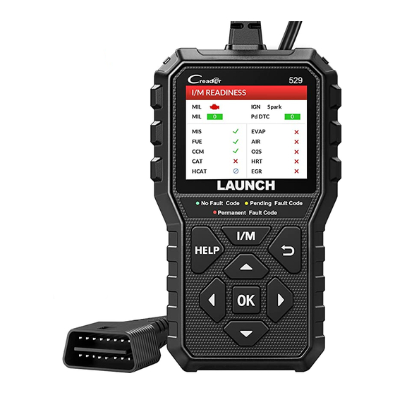
LAUNCH
529 OBD II Scanner User's Manual
Revised date: Sept. 10, 2019
Version: V1.00.000
LAUNCH owns the complete intellectual property rights for the software used by this
product. For any reverse engineering or cracking actions against the software, LAUNCH
will block the use of this product and reserve the right to pursue their legal liabilities.
I
Advertisement
Table of Contents

Related Manuals for Launch Creader 529


Summary of Contents for Launch Creader 529
- Page 1 Revised date: Sept. 10, 2019 Version: V1.00.000 LAUNCH owns the complete intellectual property rights for the software used by this product. For any reverse engineering or cracking actions against the software, LAUNCH will block the use of this product and reserve the right to pursue their legal liabilities.
- Page 2 529 OBD II Scanner User’s Manual Copyright Information Copyright © 2019 by LAUNCH TECH CO., LTD. All rights reserved. No part of this publication may be reproduced, stored in a retrieval system, or transmitted in any form or by any means, electronic, mechanical, photocopying, recording or otherwise, without the prior written permission of LAUNCH.
- Page 3 The right is reserved to make change at any time without notice. • Neither LAUNCH nor its affiliates shall be liable to the purchaser of this unit or third parties for damages, losses, costs or expenses incurred by...
- Page 4 LAUNCH 529 OBD II Scanner User’s Manual unattended while running tests. • Use extreme caution when working around the ignition coil, distributor cap, ignition wires and spark plugs. These components create hazardous voltages when the engine is running. • Put the transmission in P (for A/T) or N (for M/T) and make sure the parking brake is engaged.
-
Page 5: Table Of Contents
LAUNCH 529 OBD II Scanner User’s Manual Table of Contents 1. Introduction ..................1 2. General Information-About OBD II/EOBD ......... 3 2.1 On-Board Diagnostics (OBD) I ..............3 2.2 On-Board Diagnostics (OBD) II ..............3 2.3 Diagnostic Trouble Codes (DTCs) .............. 5 2.4 Location of the Data Link Connector (DLC).......... - Page 6 LAUNCH 529 OBD II Scanner User’s Manual 5.7.3 Beeper ....................41 5.8 Info......................41 6. Upgrade ....................42 7. FAQ ..................... 45...
-
Page 7: Introduction
529 OBD II Scanner User’s Manual 1. Introduction Creader 529 OBD II Scanner is developed by LAUNCH, especially for the DIY users and the servicemen of small service workshop. It supports read/clear DTCs and read data stream. With built-in help menus and code definitions,... - Page 8 LAUNCH 529 OBD II Scanner User’s Manual Note: Some 1994 and 1995 vehicles have 16-pin connectors but are not OBD II compliant. Only those vehicles with a Vehicle Emissions Control Label stating “OBD II Certified” are OBD II compliant.
-
Page 9: General Information-About Obdii/Eobd
LAUNCH 529 OBD II Scanner User’s Manual 2. General Information-About OBDII/EOBD 2.1 On-Board Diagnostics (OBD) I Note: With the exception of some 1994 and 1995 vehicles, most vehicles from 1982 to 1995 are equipped with some type of first generation On-Board Diagnostics. - Page 10 LAUNCH 529 OBD II Scanner User’s Manual showed the following: • A large number of vehicles had deteriorating or degraded emissions-related components. These components were causing an increase in emissions. • Because OBD I systems only detect failed components, the degraded components were not setting codes.
-
Page 11: Diagnostic Trouble Codes (Dtcs)
LAUNCH 529 OBD II Scanner User’s Manual • To standardize communication procedures and protocols between the diagnostic equipment (Diagnostic Tools, Code Readers, etc.) and the vehicle’s on-board computer. 2.3 Diagnostic Trouble Codes (DTCs) OBD II Diagnostic Trouble Codes are codes that are stored by the on-board computer diagnostic system in response to a problem found in the vehicle. -
Page 12: Location Of The Data Link Connector (Dlc)
LAUNCH 529 OBD II Scanner User’s Manual P0201 - Injector circuit malfunction, Cylinder 1 2.4 Location of the Data Link Connector (DLC) The DLC (Data Link Connector or Diagnostic Link Connector) is the standardized 16-cavity connector where diagnostic code readers interface with... -
Page 13: Obd Ii Terminology
LAUNCH 529 OBD II Scanner User’s Manual the center of the instrument panel (dash), under or around the driver’s side for most vehicles. If Data Link Connector is not located under dashboard, a label should be there telling location. For some Asian and European vehicles, the DLC is located behind the ashtray and the ashtray must be removed to access the connector. - Page 14 LAUNCH 529 OBD II Scanner User’s Manual Enabling Criteria -- Also termed Enabling Conditions. They are the vehicle- specific events or conditions that must occur within the engine before the various monitors will set, or run. Some monitors require the vehicle to follow a prescribed “drive cycle”...
-
Page 15: Obd Ii Monitors
LAUNCH 529 OBD II Scanner User’s Manual refers to much more gradual adjustments to the fuel calibration schedule than short-term trim adjustments. These long-term adjustments compensate for vehicle differences and gradual changes that occur over time. 2.6 OBD II Monitors An important part of a vehicle’s OBD II system is the Readiness Monitors,... - Page 16 LAUNCH 529 OBD II Scanner User’s Manual to “flash” once per second as soon as the misfire is sensed. When the misfire is no longer present, the MIL reverts to steady “On” condition. The Misfire Monitor is supported by both “spark ignition” vehicles and “compression ignition”...
-
Page 17: Non-Continuous Monitors
LAUNCH 529 OBD II Scanner User’s Manual 2.6.2 Non-Continuous Monitors “Non-continuous” Monitors perform and complete their testing once per trip. The “non-continuous” Monitors are: 1. O2 Sensor Monitor The Oxygen Sensor monitors how much oxygen is in the vehicle’s exhaust. It generates a varying voltage of up to one volt, based on how much oxygen is in the exhaust gas, and sends the signal to the computer. - Page 18 LAUNCH 529 OBD II Scanner User’s Manual vehicle operation. When the vehicle is operating in closed-loop, the computer uses the oxygen sensor signal for air/fuel mixture corrections. In order for the computer to enter closed-loop operation, the oxygen sensor must reach a temperature of at least 600°F. The oxygen sensor heater helps the oxygen sensor reach and maintain its minimum operating temperature (600°F) more quickly, to bring the vehicle into closed-loop operation as soon...
- Page 19 LAUNCH 529 OBD II Scanner User’s Manual converter. The main difference is that a heater is added to bring the catalytic converter to its operating temperature more quickly. This helps reduce emissions by reducing the converter’s down time when the engine is cold. The Heated Catalyst Monitor performs the same diagnostic tests as the catalyst Monitor, and also tests the catalytic converter’s heater for proper operation.
-
Page 20: Obd Ii Reference Table
LAUNCH 529 OBD II Scanner User’s Manual engine vacuum to draw the fuel vapors from the canister into the engine where the vapors are burned. The EVAP Monitor checks for proper fuel vapor flow to the engine, and pressurizes the system to test for leaks. The computer runs this Monitor once per trip. - Page 21 LAUNCH 529 OBD II Scanner User’s Manual B. Number of trips needed, with a fault present, to set a pending DTC. C. Number of consecutive trips needed, with a fault present, to command the MIL “On” and store a DTC.
-
Page 22: Dtcs And Mil Status
LAUNCH 529 OBD II Scanner User’s Manual Secondary Air System Once per trip 3 trips Monitor 2.7 DTCs and MIL Status When the vehicle’s on-board computer detects a failure in an emissions- related component or system, the computer’s internal diagnostic program assigns a diagnostic trouble code (DTC) that points to the system (and subsystem) where the fault was found. - Page 23 LAUNCH 529 OBD II Scanner User’s Manual • The computer sets a Pending DTC, but the MIL is not ordered “On.” “Freeze Frame” data may or may not be saved at this time depending on manufacturer. The Pending DTC is saved in the computer’s memory for later retrieval.
-
Page 24: Components & Controls
LAUNCH 529 OBD II Scanner User’s Manual 3. Components & Controls 3.1 Controls Name Notes Cable with OBD II Connects the scanner to the vehicle’s CONNECTOR Data Link Connector (DLC). Shows menu and submenus and test LCD SCREEN results. - Page 25 LAUNCH 529 OBD II Scanner User’s Manual • Quick access to I/M readiness function. I/M BUTTON* (See Note1) • Deletes the diagnostic record in the Print function module. BUTTON Returns to previous menu. (See Note2) When in MENU mode, scroll UP through...
-
Page 26: Specifications
LAUNCH 529 OBD II Scanner User’s Manual The following (green, yellow and red LEDs) are used as visual aids to make it easier to determine engine system conditions. • GREEN LED (No Fault Code): Indicates that all engine systems are... -
Page 27: Accessories
LAUNCH 529 OBD II Scanner User’s Manual 3.3 Accessories 1) Creader 529 OBD II Scanner 2) Quick Start Guide 3) USB cable -- Connect to a computer for upgrading online... -
Page 28: Initial Use
LAUNCH 529 OBD II Scanner User’s Manual 4. Initial Use 4.1 Connection 1) Turn the ignition off. 2) Locate the vehicle’s 16-pin Data Link Connector (DLC). 3) Plug the diagnostic cable of the scanner into the vehicle’s DLC. Notes: • A plastic DLC cover may be found for some vehicles and you need to remove it before plugging the diagnostic cable. -
Page 29: Job Menu
LAUNCH 529 OBD II Scanner User’s Manual CAUTION: Don’t connect or disconnect any test equipment with ignition on or engine running. 5) The system automatically turns on and navigates to the Job menu screen. 4.2 Job Menu The Job Menu includes the following function modules:... - Page 30 LAUNCH 529 OBD II Scanner User’s Manual Prints the diagnostic records saved during diagnostic session. PRINT *Note: This function required a USB cable connection to PC. Helps you have a general knowledge of the OBD, Data HELP stream and I/M etc.
-
Page 31: Operations
LAUNCH 529 OBD II Scanner User’s Manual 5. Operations 5.1 Start Diagnostics After the scanner is properly connected to the vehicle’s DLC, select [Diagnose] in the Job Menu and press [OK]. The scanner will automatically start a check of the vehicle’s computer to determine which type of communication protocol it is using. - Page 32 LAUNCH 529 OBD II Scanner User’s Manual 1. Read Codes This function allows you to view the Diagnostic Trouble Codes (DTCs) retrieved from the vehicle’s on-board computer. Note: Never replace a part based only on the DTC definition. Each DTC has a set of testing procedures, instructions and flow charts that must be followed to confirm the location of the problem.
- Page 33 LAUNCH 529 OBD II Scanner User’s Manual Figure 5-4 • If the GREEN LED on the scanner lights up, it indicates that all engine systems are “OK” and operating normally. All monitors supported by the vehicle have run and performed their diagnostic testing, and no trouble codes are present.
- Page 34 LAUNCH 529 OBD II Scanner User’s Manual The screen will also show the content of the code below the number of code. Press [ ] to view the next code. Press [OK] to record the diagnostic trouble code for later printing. The saved records are stored in “Print”...
- Page 35 LAUNCH 529 OBD II Scanner User’s Manual Figure 5-7 Press [OK] to erase DTCs, and the screen will display the interface as shown below: Figure 5-8 Follow the on-screen prompts to turn the ignition on with engine off, press [OK] to clear the DTCs.
- Page 36 LAUNCH 529 OBD II Scanner User’s Manual 3. I/M Readiness I/M refers to Inspection and Maintenance that is legislated by the Government to meet federal clean-air standards. I/M Readiness indicates whether or not the various emissions-related systems on the vehicle are operating properly and are ready for Inspection and Maintenance testing.
- Page 37 LAUNCH 529 OBD II Scanner User’s Manual Pending Diagnostic Trouble Code Note: If a “Pending” DTC is present, it indicates that there is a possible problem and/or some of the vehicle’s Pd DTC emission monitor have not run their diagnostic testing.
- Page 38 LAUNCH 529 OBD II Scanner User’s Manual 4. Data Stream Select [Data Stream] from the Diagnostic Menu and press [OK], the following screen will appear. Figure 5-10 • Select [View All Items] and press [OK] button, the screen will display the...
- Page 39 LAUNCH 529 OBD II Scanner User’s Manual Figure 5-12 Press the [ ] / [ ] button to check data stream items, and press the [ ] / [ ] button to turn page. After selecting items, press [ ], the screen will display the selected data stream items.
- Page 40 LAUNCH 529 OBD II Scanner User’s Manual 6. O2 sensor test OBD II regulations require that applicable vehicles monitor and test operation of the oxygen (O2) sensors to identify problems that can affect fuel efficiency and vehicle emissions. These tests are performed automatically when engine operating conditions are within predefined limits.
-
Page 41: I/M Readiness
LAUNCH 529 OBD II Scanner User’s Manual the vehicle’s control module(s). • CVN (Calibration Verification Number). CVNs are used to CVNs are used to determine if emission-related calibrations for the vehicle under test have been changed. One or more CVNs may be returned by the vehicle’s computer. -
Page 42: Print
LAUNCH 529 OBD II Scanner User’s Manual Figure 5-14 Press [HELP] to view the diagnostic tips/solution associated with the current DTC. Figure 5-15 After viewing the definition, press [ ] to return to the Job menu. 5.5 Print This function is used to print the records saved on the Read Codes or Data Stream screen. - Page 43 LAUNCH 529 OBD II Scanner User’s Manual 972893000004 6411384A3230 Figure 5-16 2. Press [ ] to enter the normal mode and naviage to the Job menu screen. 3. Run the update tool on your PC, the following screen will appear.
- Page 44 LAUNCH 529 OBD II Scanner User’s Manual Note: After the system identified the scanner information, it will display in gray in Product Serial Number input box and the "Print Manager" module will be activated immediately. 3. Click [Print Manager] to enter the print manager screen.
- Page 45 LAUNCH 529 OBD II Scanner User’s Manual Figure 5-21 On-screen buttons: : Allows you to modify the personal information. Configured information is automatically generated and displayed on the top of the report each time the diagnostic report is synchronized on the computer.
-
Page 46: Help
LAUNCH 529 OBD II Scanner User’s Manual 5.6 Help This function allows you to have a general knowledge of OBD, Data stream and I/M Readiness. • About OBD: Relevant introduction information about OBD. • About Data stream: Relevant introduction information about Data stream. -
Page 47: Unit Of Measure
LAUNCH 529 OBD II Scanner User’s Manual 5.7.2 Unit of Measure This option allows you to set measurement unit. Choose [Unit of Measure] and press [OK] to enter the measurement unit selection page. Press [ ] / [ ] to select the desired one and press [OK] to save your change. -
Page 48: Upgrade
LAUNCH 529 OBD II Scanner User’s Manual 6. Upgrade The scanner can be updated via USB cable. Note: Make sure the PC has an Internet connection. 1. Go to http://www.x431.com/CR529 and download the update tool to the computer. 2. Decompress and install it on your computer(compatible with Windows XP, Windows 7, Windows 8 &... - Page 49 LAUNCH 529 OBD II Scanner User’s Manual Figure 6-3 Note: After the system identified the scanner information, it will display in gray in Product Serial Number input box and the "Print Manager" module will be activated immediately. 6. Choose the desired interface language and click [Device Upgrade], a screen similar to the following figure will appear.
- Page 50 LAUNCH 529 OBD II Scanner User’s Manual 8. Once update is complete, a “Upgrade success” message box will pop up. 9. The update process is complete, your scanner is now ready for use.
-
Page 51: Faq
LAUNCH 529 OBD II Scanner User’s Manual 7. FAQ Here we list some frequently asked questions and answers related to this OBD II scanner. Q: System halts when reading data stream. What is the reason? A: It may be caused by a slackened connector. Please turn off the scanner, firmly connect the connector, and switch it on again. - Page 52 The exclusive remedy for any automotive meter found to be defective is repair or replacement, and LAUNCH shall not be liable for any consequential or incidental damages.
Need help?
Do you have a question about the Creader 529 and is the answer not in the manual?
Questions and answers
How to activate launch creader 529 scanning tool, And it is showing same issues in different cars.