
Related Manuals for Timeguard LED200PIRBE


Summary of Contents for Timeguard LED200PIRBE
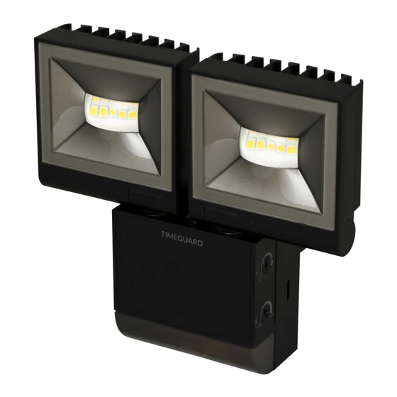
- Page 1 2x 10W LED Slimline PIR Floodlight – Twin Flood Model: LED200PIRBE – Black Model: LED200PIRWHE – White...
-
Page 2: General Information
1. General Information These instructions should be read carefully and retained for further reference and maintenance. 2. Safety • Before installation or maintenance, ensure the mains supply to the luminaire is switched off and the circuit supply fuses are removed or the circuit breaker turned off. -
Page 3: Selecting A Location
• Lux Adjustment: 2 to 200 lux • Stand-by Power Consumption: 0.4W • Warm-up Duration: 30 seconds • Colour Temperature: 4000K • Operating Temperature: - -20°C to +45°C • Manual Pulse Override: Double flip within 2 seconds to enter 6 hours ON time •... -
Page 4: Installation
• A moving human body needs to cross/enter one of these zones to activate the PIR sensor. The best all-round coverage is achieved with the floodlight mounted at the optimum height of 2.5 metres. See image B. • Careful positioning of the PIR sensor will be required to ensure optimum performance. - Page 5 5.2 An isolating switch should be installed to enable the power to be switched ON and OFF for maintenance purposes and to activate the manual/auto override function. 5.3 Disconnect the back box from the luminaire by releasing the lugs (left or right side). See Image 2.
- Page 6 5.7 Terminate the 230V 50Hz mains supply cable into the terminal block (See image 6) ensuring correct polarity is observed and that all bare conductors are sleeved (See section 6. Connection Diagram – for wiring details). 5.8 Re-connect the luminaire to the back box ensuring the 2 lugs firmly latch on the left and right hand side, indicated by a ‘click’...
-
Page 7: Connection Diagram
6. Connection Diagram 230V AC 50Hz MAINS SUPPLY ISOLATION SWITCH Connect the 3 core mains supply cable top the terminal block on the back box as follows: Live Supply (Brown or Red) to Neutral Supply (Blue or Black) to Earth (Green/Yellow) to For additional external (slave) lighting, connect the external load to the terminal block on the back box as follows: Live Supply (Brown or Red) to... - Page 8 Parallel Switching • A maximum of 4x LED200PIR twin floodlights can be wired in parallel to enable any detector to turn ON all the lights connected. • Please refer to the following diagram which shows and example of 2x LED200PIR twin floodlights connected in parallel, with 2 slave floodlights at the same time: 7.
- Page 9 • The unit will now operate during daytime as well as at night, illuminating the lamp for approx. 2 seconds each time. This allows testing to be carried out to establish whether the sensor is covering the required area. • Walk across the location the sensor is fitted, to establish the detection zone. •...
-
Page 10: Lamp Adjustment
If the unit starts to operate too late (i.e. when it is very dark). Adjust the control slightly clockwise. • Continue to adjust until the unit operates as desired. Knob Adjuster (Included in Thin flat head accessory pack) screwdriver 8. Lamp Adjustment •... -
Page 11: Year Guarantee
Note: A proof of purchase is required in all cases. For all eligible replacements (where agreed by Timeguard) the customer is responsible for all shipping/postage charges outside of the UK. All shipping costs are to be paid in advance before a replacement... - Page 12 If you experience problems, do not immediately return the unit to the store. Telephone the Timeguard Customer Helpline; HELPLINE 020 8450 0515 or email helpline timeguard.com Qualified Customer Support Co-ordinators will be on-line to assist in resolving your query. For a product brochure please contact: Timeguard Limited.
Need help?
Do you have a question about the LED200PIRBE and is the answer not in the manual?
Questions and answers