Table of Contents
Advertisement
Quick Links
Advertisement
Table of Contents

Related Manuals for Samsung VMR-O P3.9


Summary of Contents for Samsung VMR-O P3.9
- Page 1 Product Manual VMR-O P3.9 1 / 66...
-
Page 2: Table Of Contents
Catalogue Catalogue........................2 1.1 VMR-O HD Series Product Introduction..........3 1.2 Product Outlook..................4 Chapter 2 Safety......................4 2.1 Safety Guidelines..................5 2.2 Safety Statement...................5 2.3 Warning Statement................6 2.4 Instructions for Use................7 Chapter 3 VMR-O Product Installation Requirements...........8 3.1 Structure Requirements............... 8 3.2 Electrical Requirement................. 8 3.3 Computer &... -
Page 3: Vmr-O Hd Series Product Introduction
Dear users, you are welcome to use Samsung products. We are very pleased if this manual is helpful for you. This manual is intended to provide you with an installation instruction. If you encounter any problems during usage, or if you have any suggestions, please contact us according to the contact information in the manual, We will try our best to solve this problem. -
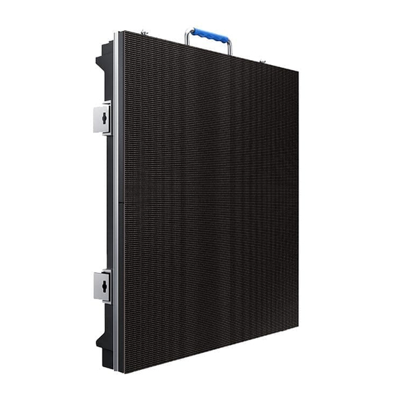
Page 4: Product Outlook
VMR-O Series, please ensure that you understand and follow the safety guidelines, safety instructions and warnings in this section. In this manual, the “VMR-O HD Series” contains the following products from the company: for Outdoor Use: VMR-O P3.9. 4 / 66... -
Page 5: Safety Guidelines
VMR-O HD series; Please follow the assembly instructions when installing the cabinet. If you encounter any problems during the installation, please contact Samsung in time. Product Care The cabinet should be kept dry and clean. It is recommended that users conduct ... -
Page 6: Warning Statement
cabinet from falling. After the screen installation and connection is completed, do not step on the plug, socket, power/signal cable. Please use the accessories/accessories specified by our company. 2.3 Warning Statement Do not open the internal equipment of the cabinet to reduce the risk of electric ... -
Page 7: Instructions For Use
Please provide a good ventilation environment for the display to facilitate the heat dissipation of the display; and keep away from flammable and explosive materials. Since the display LED lamps of the VMR-O HD series are relatively fragile, do not ... -
Page 8: Chapter 3 Vmr-O Product Installation Requirements
ground surface is flat and hard without slope. The ground easily to sunken is not proper for installation. Stacking requirements: Samsung Company provides customers with supporting floor stacking brackets to quickly install the display anytime, anywhere. The floor stand is set in units, and multiple sets can be quickly combined to form a large stacking frame. -
Page 9: Chapter 4 Displaying System
can display 1080P HD images, and the discrete graphics card has HDMI or DVI output interfaces. Computer system requirements: WindowsXP, Win7, Win8, WIN10; supporting software: Media Player (MediaPlayer), ultimate decoder (finalcodecs), office software. LED display setting software: the latest version of NovaLCT-Mars. ... -
Page 10: Chapter 5 Vmr-O Main Components & Accessories
Remarks: Picture 4-1 is only the most basic configuration of the LED display system. If necessary, you need to add multiple sending boxs, video processors, video players and other equipment. Chapter 5 VMR-O Main Components & Accessories This chapter illustrated the detailed spec and features of main components and accessories of VMR-O HD series products so that customers can understand the company's products more quickly and intuitively. - Page 11 12. Automatic locking piece----With the locking lever, quick connection and locking the adjacent cabinet; Remark: The module housing in the Picture is applicable to VMR-O P3.9 Main power cable: Power supply to the display, the wire diameter is 3*2.5mm², and the maximum load current is 16A, as shown in Picture 5-2.
- Page 12 Picture 5-3 Main signal cable Cabinet power cable: Connect the power supply box between the cabinet and the cabinet. The cable size is 3*2.5mm², as shown in Picture 5-4. Picture 5-4 Cabinet Power Line Cabinet signal cable: Connects the signal between the cabinet and the cabinet, and exceeds the five types of network cables, as shown in Picture 5-5.
-
Page 13: Mounting Accessories
5.2 Mounting Accessories 5.2.1 Hanging block: Lift the display when lifting, as shown in Picture 5-6. Picture 5-6 Hanging Bar For holding the truss For Locking the locking bars of the two adjacent cabinets 5.2.2 Floor stacking bracket: The stacking bracket can be freely combined into a larger frame to meet the installation requirements, as shown in Picture 5-7. -
Page 14: Power Distribution Cabinet
Picture 5-7 Foldable Bracket ① Stacking base beam and standing base bar Maintenance channel board ② ③ Connector ④ Support Truss Frame 5.3 Power Distribution Cabinet Powering the entire display system As Picture 5-9 show: Picture 5-9 Power Distribution Cabinet 14 / 66... -
Page 15: Controller System
Remarks: Samsung Company provides customers with standard power distribution cabinets with 8, 12, and 16 interfaces. It can also customize special power distribution cabinets for customers, such as power distribution cabinets with remote power-on functions and more interfaces. 5.4 Controller System Sending box: ... - Page 16 Picture 5-11 Receiver Card Control software: The control software installed on the computer can set the display parameters, display brightness adjustment and other functions. The software interface is shown in Picture 5-12. Picture 5-12 NovaLCT-Mars Control System Interface Video processor: ...
-
Page 17: Other Accessories
shown in Picture 5-13. (Different items will choose different types of video processors, the appearance and function will be different). Picture 5-13 Video Processor HD media player: It can play 4K HD video and provide high-quality video source for the display. The physical object is shown in Picture 5-14. -
Page 18: Chapter 6 Vmr-O Installation Process
Flight Case: According to the customer's requirements, the flightcase with waterproof function is specially designed for convenient transportation and convenient loading and unloading; as shown in Picture 5-17. Picture 5-16 Flight Case Chapter 6 VMR-O Installation Process This chapter mainly introduces the installation process of the VMR-O HD series products and guides the customer to install the products correctly. - Page 19 1. Select the installation area of the VMR-O HD display and enclose it with a safety warning band. Non-workers are not allowed to enter without permission, keeping the installation area clean, free from dirt and debris. 2. Ensure that you have read, understood and followed all of the safety issues mentioned in Chapter 1 before installation;...
- Page 20 Picture 6-3 Supporting Frame Step 4: Install the maintenance access board. Fix the maintenance access board on the bracket as shown below, which is convenient for maintenance, as shown in Picture 6-4. Picture 6-4 Maintenance Access Board Step 5: Install the bracket connector. The height of the connector is determined by the height of the cabinet, as shown in Picture 6-5.
- Page 21 Picture 6-5 Bracket Connector 6.1.3 Cabinet Installation 1. First, wear anti-static gloves and operate with more than one person. 2. Take off the cabinet from the flightcase in a slowly and gentle way, and unwrap the PE package and press the automatic protection angle. [If the cabinet is not equipped with the automatic corner guard, the sheet metal corner can be removed with a screwdriver] And place the cabinet completely on the ground or on the desktop, as shown in Picture 6-6, 6-7.
- Page 22 3. Start installing the cabinet. After ensuring that the base beam is flat, gently place and lock each cabinet. Each time a cabinet is erected, a cabinet is lit immediately to check if any dead lights, obvious bright lines, and flatness. When a cabinet is stacked on the other, immediately locked the connecting piece, and connect the cabinet to the stacking bracket via bracket connector, as shown in Fig.
-
Page 23: Hanging
6.2 Hanging In the case of installation locations changing frequently, hanging is usually used, which is common in the rental market. For the VMR-O HD Series, Samsung provides customers with a truss and FlyKit for quick haing installation. The following are detailed steps. - Page 24 Picture 6-11 Truss Install the FLYKIT and install the FLYKIT according to the position of the upper and lower locking bars of the cabinet, as shown in Picture 6-12. Picture 6-12 Hanging Bra Installation 3. Cabinet Installation Picture 6-13 Cabinet Installation 1.
- Page 25 the automatic corner guard, the side of the sheet metal corner needs to be removed with a screwdriver to remove the corner guard.] Place it on the ground or on the table, as shown in Pictures 6-14, 6-15. Picture 6-14 Take out Cabinet Picture 6-15 Press to protect the automatic corner...
-
Page 26: Chapter 7 Vmr-O Cable Connection
Chapter 7 VMR-O Cable Connection This chapter describes how the signal and power cables of the VMR-O HD Series are connected. 7.1 VMR-O HD series product cabinet interface introduction Picture 7-1 VMR-O Cabinet Connection Port ① Power Output ② Power Input ③... -
Page 27: Power Cable Connection
7.2 Power Cable Connection 7.2.1 Power Distribution Cabinet: Each VMR-O HD display requires a power distribution cabinet. Samsung provides customers with a variety of power distribution cabinets. It also customizes the matching power distribution cabinets for specific projects. And the connection can refer to the relevant manual. -
Page 28: Signal Cable Connection
2. Install the cabinet, refer to Chapter 6. 3. After the cabinet is installed, connect the signal wires according to the design drawings. Picture 7-3 shows the signal cable connection of the VMR-O P3.9 15*8 arrangement. 28 / 66... - Page 29 Each main network cable carries 128*128*32=524288 pixels. ① Sending box ② Main signal cable ③ Cabinet signal cable Picture 7-3 Signal connection diagram Product Name Daisy Chain (Cabinet Qty for 1 main signal cable to cascade) (575,000pixels)35PCS-39PCS(650,000pixels) VMR-O -P Remarks: The number of pixels carried on each main network cable of the sending box is limited, and the actual project should refer to the corresponding signal connection diagram.
-
Page 30: Chapter 8 Vmr-O Displaying Set-Up Steps
Chapter 8 VMR-O Displaying Set-up Steps This chapter mainly introduces the setup steps of the VMR-O series product control software. 8.1 NovaLct-Mars Control System Instruction 8.1.1 Load display profile Double-click to open the NovaLCT-Mars software, as shown in Picture 8-10, click “User”—“Advanced Login”... - Page 31 Picture 8-11 Click the “load files” button on the Scan Board interface, load the “*.rcfgx” file corresponding to the display, and then click the “Send to HW” button. After the display shows normal, click “Save”, as shown in Picture 8-12. Picture 8-13. Picture 8-12 Picture 8-13 31 / 66...
- Page 32 Picture 8-14 Note: Do not modify any parameters after the non-professionals load the "*.rcfgx" file. If the parameters are inadvertently modified, the display screen will not display properly. The configuration file needs to be reloaded and sent to the receiving card. After sending and saving the configuration file, the display should display the same content in units of the cabinet.
- Page 33 Picture 8-15 Picture 8-16 Note: Do not modify any parameters after non-professionals load the "*.Scr" file. If the parameters are inadvertently modified, the display screen is not displayed properly. The screen file needs to be reloaded and sent to the receiver card.
-
Page 34: Appendix A Dimensional Drawing Of Main Components
Appendix A Dimensional Drawing of Main Components A.1 VMR-O VMR-O P3.9 Flat Panel Curve Panel A.2 Flykit 34 / 66... -
Page 35: Appendix B Vmr-O Specification Table
Appendix B VMR-O Specification Table Product Name VMR-O P 3.9 Physical Pitch 3.9 mm LED Vendor Nationstar LED Package Name FM-Z1921 RGBA-SH Size of LED color bin combination R:5nm, G:3nm, B:3nm No. of LED Bin for 1 project Single Bin D-IC Vendor Chipone D-IC part name... - Page 36 Packaging Weight 23±2 kg/panel Packaging Method (Flight Case) Packaging Dimensions (W × H × D) N/A Packaging Weight Brightness (after Cal.) ≥4500nits Refresh Rate 1920 Hz Horizontal Viewing Angle 140° Vertical Viewing Angle 120° Color temperature Optical/ Video - Default 12000K±500K -Adjustable range 3500~12,000K...
- Page 37 Accessory List Items Specs Remark 202005000242R Module Outdoor Module Outdoor 3.9 (64*64) 114001000A4SR Receiving card Receiver Card 115309258010R Power supply Power Supply 300W 300W 204030000050B HUB board HUB board outdoor 3.9 outdoor 3.9 204050000097B Connection plate connecting plate outdoor 3.9 outdoor 3.9 Power cord 208030200204R...
- Page 38 Main power cord 208030100103R Main power cord (SEETRONIC outdoor, (SEETRONIC European outdoor, European standard plug) standard plug) 209010200054R Main signal Main signal cable cable 30M (SEETRONIC (SEETRONIC outdoor) outdoor) Mask Outdoor 120200207146R Mask Outdoor 3.9 110000290001R Light Nationstar Lights National 1921 Star 1921 110900203801R...
- Page 39 120100506124R Connection connecting piece piece,Screws 120300304011R screw For fixed application only 120500207012R (SEETRONIC (SEETRONIC outdoor mother) outdoor female) power aviation power aviation head head 120500207013R (SEETRONIC (SEETRONIC outdoor public) outdoor male) power aviation power aviation head head 120500407026R (SEETRONIC (SEETRONIC outdoor) signal outdoor) signal aviation head...
-
Page 40: Appendix C Tools To Be Prepared
Appendix C Tools to be prepared C.1 Adjustable Wrench (conventional) C.2 Screwdriver (medium size) C.3 Cutting pliers (conventional) C.4 Allen key (M3 is used to open the power cabinet, M8 is used to fix the connecting piece) 40 / 66... - Page 41 C.5 Plastic hammer 41 / 66...
-
Page 42: Appendix D How To Use The Air Suction Tool
Appendix D How to use the air suction tool 1 Attach the air suction tool to the surface of the module to be removed, and press it slightly on the surface of the module so that the suction cup of the suction tool fits evenly with the module surface, as shown in the following Picture: Press and hold the air suction tool switch for 3~5 seconds, and the air suction tool sucks the module;... - Page 43 Pull the air suction tool out with one hand and remove the module with one hand, as shown below: After removing the module, release the air suction tool switch and the module is successfully removed, as shown below: Remarks: The VMR-O HD series is a small-pitch product that is very easy to damage. All the actions need to be handled gently during the process of disassembling the module.
-
Page 44: Appendix E How To Use The Upper And Lower Lock Levers
Appendix E How to use the upper and lower lock levers E.1.1 Stack one panel onto the other. E.1.2 Push the lock lever up as shown below: 44 / 66... - Page 45 E.1.3 The lock lever is pushed up into position and the lock bar lock lever is as shown below: E.1.4 Move the handle to the inside according to the arrow of the cabinet, so that the handle is pressed against the cabinet, as shown below: E.1.5 Locking status as shown below 45 / 66...
- Page 46 E.1.6 Locate the left and right locks and unlock them. Turn the lock lever handle according to the UNLOCK direction of the cabinet to the point where it cannot be rotated. Then push the lock piece pointed by the arrow to unlock it, as shown below: E.2.1 Initial state: When the cabinet is installed, the position of the upper right lock lever is as shown below.
- Page 47 E.2.2 Push the lock lever up as shown below: E.2.3 The lock lever is pushed up into position and the lock bar lock lever is as shown below: E.2.4 Move the handle to the inside of the cabinet arrow to press the handle to the cabinet, as shown below: 47 / 66...
- Page 48 E.2.5 The locking state is as follows: E.2.6 Locate the left and right locks and unlock them. Turn the lock lever handle according to the UNLOCK direction of the cabinet to the point where it cannot be rotated. Then push the lock piece pointed by the arrow to unlock it, as shown below: 48 / 66...
- Page 49 49 / 66...
-
Page 50: Appendix F How To Use The Left And Right Angle Locks
Appendix F How to use the left and right angle locks Initial state: The initial state of the angle lock is as shown in the Picture below. Adjust the position as shown in the Picture below to the desired angle. F2:... - Page 51 F3:Align the left and right cabinets together, as shown below; Push the lock lever to the left as shown below: F5: Turn the lock lever 90° clockwise as shown below: 51 / 66...
- Page 52 F6: The position of the lock lever is as shown below, as shown below: Turn the lock lever handle according to the mark on the cabinet, as shown below: 52 / 66...
- Page 53 Press the lock handle according to the mark to lock the cabinet, as shown below: 53 / 66...
-
Page 54: Appendix G How To Take Off The Power Cabinet
Appendix G How to Take off the power cabinet Use the M3 Allen key to turn the fuse button in the direction of the mark, as shown below: Press the four buckles shown below and open them as shown below: G3:Hold both ends of the power cabinet with both hands and pull the power cabinet backwards, as shown below: 54 / 66... - Page 55 G4: Open the back cover of the power supply cabinet as shown below, as shown below: 55 / 66...
-
Page 56: Appendix H Common Troubleshooting Methods
Appendix H common troubleshooting methods A. The screen does not light or keeps flashing 1. Check if the power supply is powered. As shown in Picture 1 below: Picture 1 2. Check if the DVI cable the signal cable are in good contact or not. As shown in Picture 2 below 3. - Page 57 B. Module Failure: 1. The single lamp has no light, and the LED itself is damaged, resulting in a dead lamp. As shown in Picture 4: Picture 4 2. A string of lamps are not lit or constantly lit: one of the 16-bit pins of the constant current IC is damaged or in pseudo soldering.
- Page 58 Picture 6 4. If a module is not lit, the socket of the module may be too loose to be powered. (As shown in Picture 7) Picture 7 5. If one or several lines of the module are not lit, the tube may be damaged. If the module shows a lack of color, it may be 245 soldered or damaged.
- Page 59 Picture 1 D Replacement Method: 1. Replace the receiving card: Step 1: Remove the two screws that secure the receiving card with a Phillips screwdriver. Step 2: Take the card vertically with your hand. Step 3: After the new receiving card is installed, lock the screw to fix the receiving card. 59 / 66...
- Page 60 2. Replace the HUB board: Step 1: Remove the six white screws that secure the HUB board with a Phillips screwdriver. Step 2: Remove the four white screws that secure the HUB board with a Phillips screwdriver. 60 / 66...
- Page 61 Step 3: Unplug the network cables at the upper and lower ends. Step 4: Unplug the line of the indicator light. 61 / 66...
- Page 62 Step 5: Take the new HUB board, lock the 6 white Phillips screws, and then lock the 4 white screws to connect the positive and negative poles. Finally, plug in the Internet cable and indicator cable. 3. Replace the power supply: Step 1: Remove the HUB board with a Phillips screwdriver and replace the HUB with the same procedure.
- Page 63 Step 2: Remove the 4 screws of the fixed power supply with a Phillips screwdriver. Step 3: Remove the power supply at the AC input terminals L, N, and G. 63 / 66...
- Page 64 Step 3: Take a new power supply, use a Phillips screwdriver to lock the 4 screws to fix the power supply, and then fix the power connection cable between the input terminal and the output terminal according to the corresponding polarity. 4.
- Page 65 Step 2: Remove the connecting plate and replace it with a new one. 5. Replace the dead light: Step 1: Use the air suction tool to remove the module. Step 2: Use the electric batch tool to remove the mask. Step 3: Remove the glue near the dead light.
- Page 66 Step 4: Remove the dead light and Put on a new light. 6. Replace the module: Step 1: Use a suction tool to remove the bad module. Refer specifically to Appendix D, “How to Use Air Suction Tools”. Step 2: Take the new module to the positioning post on the box and gently press and fix the module.