Table of Contents
Advertisement
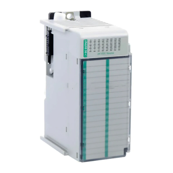
Compact 32-point Solid-state 24V dc Source
Output Module
Catalog Number 1769-OB32
Use this document as a guide when installing a Compact™ 32-point solid-state 24V dc
source output module.
Topic
Installation Instructions
Page
2
3
4
5
6
8
9
12
13
15
16
21
22
Publication 1769-IN031A-EN-P - April 2003
Advertisement
Table of Contents

Related Manuals for Allen-Bradley Compact 1769-OB32


Summary of Contents for Allen-Bradley Compact 1769-OB32
-
Page 1: Table Of Contents
Installation Instructions Compact 32-point Solid-state 24V dc Source Output Module Catalog Number 1769-OB32 Use this document as a guide when installing a Compact™ 32-point solid-state 24V dc source output module. Topic Page Important User Information Module Description Module Installation System Assembly Mounting Expansion I/O Replacing a Single Module within a System Field Wiring Connections... -
Page 2: Important User Information
Rockwell Automation does not assume responsibility or liability (to include intellectual property liability) for actual use based upon the examples shown in this publication. Allen-Bradley publication SGI-1.1, Safety Guidelines for the Application, Installation and Maintenance of Solid-State Control (available from your local Rockwell Automation office), describes some important differences between solid-state equipment and electromechanical devices that should be taken into consideration when applying products such as those described in this publication. -
Page 3: Module Description
Compact 32-point Solid-state 24V dc Source Output Module Module Description Item Description bus lever (with locking function) upper panel mounting tab lower panel mounting tab I/O diagnostic LEDs WARNING -Do Not Remove RTB Unless Area is Non-Hazardous +VDC 1 +VDC 2 OUT 0 OUT 16 OUT 1... -
Page 4: Module Installation
Compact 32-point Solid-state 24V dc Source Output Module Module Installation Compact I/O is suitable for use in an industrial environment when installed in accordance with these instructions. Specifically, this equipment is intended for use in clean, dry environments (Pollution degree 2 ) and to circuits not exceeding Over Voltage Category II (IEC 60664-1). -
Page 5: System Assembly
Compact 32-point Solid-state 24V dc Source Output Module System Assembly The module can be attached to the controller or an adjacent I/O module before or after mounting. For mounting instructions, see Panel Mounting on page 6, or DIN Rail Mounting on page 8. To work with a system that is already mounted, see Replacing a Single Module within a System on page 8. -
Page 6: Mounting Expansion I/O
Compact 32-point Solid-state 24V dc Source Output Module 7. Attach an end cap terminator (5) to the last module in the system by using the tongue-and-groove slots as before. 8. Lock the end cap bus terminator (6). A 1769-ECR or 1769-ECL right or left end cap must be used to IMPORTANT terminate the end of the serial communication bus. - Page 7 Compact 32-point Solid-state 24V dc Source Output Module Panel Mounting Using the Dimensional Template Spacing for single-wide modules 35 mm (1.378 in.) Spacing for one-and-a half-wide modules 52.5 mm (2.067 in.) Refer to host controller documentation for this dimension. Note: Overall hole spacing tolerance: ±0.4 mm (0.016 in.).
-
Page 8: Replacing A Single Module Within A System
Compact 32-point Solid-state 24V dc Source Output Module DIN Rail Mounting The module can be mounted using these DIN rails: 35 x 7.5 mm (EN 50 022 - 35 x 7.5) or 35 x 15 mm (EN 50 022 - 35 x 15). Before mounting the module on a DIN rail, close the DIN rail latches. -
Page 9: Field Wiring Connections
30527-M Recommended Surge Suppression - Use a 1N4004 diode reverse-wired across the load for transistor outputs switching 24V dc inductive loads. For additional details, refer to Industrial Automation Wiring and Grounding Guidelines, Allen-Bradley publication 1770-4.1. Sourcing Output - Source describes the current flow between the I/O module and the field device. Sourcing output circuits supply (source) current to sinking field devices. - Page 10 Compact 32-point Solid-state 24V dc Source Output Module A removable write-on label is included with the module. Remove the label from the door, mark the identification of each terminal with permanent ink, and slide the label back into the door. Your markings (ID tag) will be visible when the module door is closed.
- Page 11 Compact 32-point Solid-state 24V dc Source Output Module 2. Route the wire under the terminal pressure plate. You can use the bare wire or a spade lug. The terminals will accept a 6.35 mm (0.25 in.) spade lug. The terminal screws are non-captive. Therefore, it is possible to use a ring lug [maximum 1/4 inch o.d.
-
Page 12: I/O Memory Mapping
Compact 32-point Solid-state 24V dc Source Output Module Wire Size and Terminal Screw Torque Each terminal accepts as many as two wires with these restrictions: Wire Type Wire Size Terminal Screw Retaining Screw Torque Torque Solid Cu-90°C (194°F) #14 to #22 AWG 0.68 Nm (6 in-lbs) 0.46 Nm (4.1 in-lbs) Stranded... -
Page 13: 1769-Ob32 Configuration File
Compact 32-point Solid-state 24V dc Source Output Module The output module’s input data file reflects the output data echo IMPORTANT of the module, not necessarily the electrical state of the output terminals. It does not reflect shorted or open outputs. It is important to use this input word if the controller adapter supports the Program Mode or Fault Mode function, and if it is configured to use them. - Page 14 Compact 32-point Solid-state 24V dc Source Output Module Program State Word Condition Bit Setting Word 1, the program state word, selects the hold User-defined Safe State last state or user-defined safe state condition for Hold Last State each individual output on a system transition from Run to Program.
-
Page 15: Spare/Replacement Module Parts
Compact 32-point Solid-state 24V dc Source Output Module Module Default Condition The modules default condition is all zeros, programming the conditions shown. Word or Bit Affected Condition Applied Word 0, Bit 0: Program-to-Fault Enable Program Value Word 1: Program State User-defined Safe State Word 2: Program Value... -
Page 16: Specifications
Compact 32-point Solid-state 24V dc Source Output Module Specifications General Specifications Specification Value Dimensions 118 mm (height) x 87 mm (depth) x 52.5 mm (width) height including mounting tabs is 138 mm 4.65 in. (height) x 3.43 in (depth) x 2.07 in (width) height including mounting tabs is 5.43 in. - Page 17 Use a 5.6K ohm, ½ watt resistor for transistor outputs, 24V dc operation. Recommended Surge Suppression - Use a 1N4004 diode reverse-wired across the load for transistor outputs switching 24V dc inductive loads. For additional details, refer to Industrial Automation Wiring and Grounding Guidelines, Allen-Bradley publication 1770-4.1.
- Page 18 Compact 32-point Solid-state 24V dc Source Output Module Temperature Derating The area within the curve represents the safe operating range for the module under various conditions of user supplied voltages and ambient temperatures. Temperature Derating 1769-OB32 Maximum Amperes per Common vs. Temperature 8.00 7.50 7.00...
- Page 19 Compact 32-point Solid-state 24V dc Source Output Module Temperature Derating 1769-OB32 Maximum Amperes per Point vs. Temperature 1.00 0.95 0.90 0.85 0.80 0.75 0.70 0.65 0.60 0.55 0.50 30˚C (86˚F) 40˚C (104˚F) 50˚C (122˚F) 60˚C (140˚F) 30526-M Ambient Termperature Transistor Output Transient Pulses The maximum duration of the transient pulse occurs when minimum load is connected to the output.
- Page 20 Compact 32-point Solid-state 24V dc Source Output Module The graph below illustrates that the duration of the transient is proportional to the load current. Therefore, as the on-state load current increases, the transient pulse decreases. Power-up transients do not exceed the time duration shown below, for the amount of loading indicated, at 60°C (140°F).
-
Page 21: Hazardous Location Considerations
Compact 32-point Solid-state 24V dc Source Output Module Hazardous Location Considerations This equipment is suitable for use in Class I, Division 2, Groups A, B, C, D or non-hazardous locations only. The following WARNING statement applies to use in hazardous locations. EXPLOSION HAZARD WARNING •... -
Page 22: For More Information
Compact 32-point Solid-state 24V dc Source Output Module For More Information Refer to this Document Pub. No. A more detailed description of how to install MicroLogix 1200 & 1500 1764-UM001B-US-P and use your Compact™ I/O with Programmable Controllers User MicroLogix™ 1200 & 1500 programmable Manual controller. - Page 23 Compact 32-point Solid-state 24V dc Source Output Module Notes: Publication 1769-IN031A-EN-P - April 2003...
- Page 24 Compact, MicroLogix, CompactLogix, RSLogix 500, and RSNetWorx for DeviceNet are trademarks of Rockwell Automation. DeviceNet is a trademark of Open DeviceNet Vendor Association (ODVA). Publication 1769-IN031A-EN-P - April 2003 PN 40071-153-01(1) © 2003 Rockwell International Corporation. Printed in the U.S.A. ´H'+U!¶1§¨...
Need help?
Do you have a question about the Compact 1769-OB32 and is the answer not in the manual?
Questions and answers