Table of Contents
Advertisement
Quick Links
Advertisement
Table of Contents

Related Manuals for Ruijie Networks RG-AM5528 Series

Summary of Contents for Ruijie Networks RG-AM5528 Series
- Page 1 RG-AM5528 Series Access point Hardware Installation and Reference Guide V1.00...
-
Page 2: Copyright Statement
Ruijie Networks reserves all copyrights of this document. Any reproduction, excerption, backup, modification, transmission, translation or commercial use of this document or any portion of this document, in any form or by any means, without the prior written consent of Ruijie Networks is prohibited. Exemption statement This document is provided “as is”. -
Page 3: Obtaining Technical Assistance
It is intended for the users who have some experience in installing and maintaining network hardware. At the same time, it is assumed that the users are already familiar with the related terms and concepts. Obtaining Technical Assistance Ruijie Networks Website: http://www.ruijienetworks.com/ Service Email: service_rj@ruijienetworks.com ... -
Page 4: Chapter 1 Product Overview
· 1 Chapter 1 Product Overview Ruijie i-Share+ solution deploys a marketing-leading distributive design and exclusive Gigabit architecture to handle high-density and complex application scenarios with ease. The hierarchical structure consists of three main components: i-Share+ Master AP, Mini AP module and 100-meter Ethernet Cable.The Master AP RG-AM5528 is designed by for next-generation high-speed wireless LAN in dense building scenario, including campus dormitories and hospital rooms. -
Page 5: Product Appearance
· Operating temperature: 0ºC to 50ºC Temperature Storage temperature: -40ºC to 70ºC Operating humidity: 10% to 90% Humidity Storage humidity: 5% to 90% Speed adjustment and fault alarm Temperature Warning Supported GB9254-2008 EMC Standards Safety Standards GB4943-2011 Dimensions (W x D x H) 440 mm x 260 mm x 44 mm Weight 5.8 kg (with package) -
Page 6: Front Panel
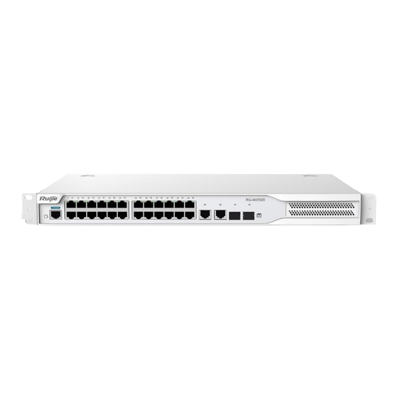
· Front Panel Figure 1-2Front Panel of RG-AM5528 Note: 1. System status LED 7. 10/100/1000Base-T auto-sensing Ethernet port 2. Copper port LED 8. 1000Base-T copper port 3. GE copper port LED 9. SFP+ port 4. Fiber port LED 5. Mode button 6. -
Page 7: Heat Dissipation
· Note: Three-hole power Grounding connector receptacle Air exhaust Heat Dissipation The RG-AM5528adopts turbine fans for heat dissipation, thereby ensuring normal function of the device in the specified environment. 10 cm distance space should be reserved at both sides and the back panel of the deviceto allow air circulation. - Page 8 · The system is being initialized. Blinking green Continuous blinking indicates faults. Solid green The access point is operational. Temperature warning Solid yellow Check the working environment of the access point immediately. Solid red The access point is faulty. Solid green The port is providing power.
- Page 9 · The port is receiving or transmitting traffic at 1000 Blinking green Mbps.
-
Page 10: Chapter 2 Preparation
· 2 Chapter 2 Preparation Safety Suggestions To avoid personal injury and equipment damage, please carefully read the safety suggestions before you install the RG-AM5528 series access point. The following safety suggestions do not cover all possible dangers. Installation ... -
Page 11: Static Discharge Damage Prevention
Proper humidity conditions Laser The RG-AM5528 series access point supports varying models of optical modules sold on the market which are Class I laser products. Improper use of optical modules may cause damage. Therefore, pay attention to the following when you use them: ... - Page 12 In an environment with high temperature, the equipment is subject to even greater harm, as its performance may degrade significantly and various hardware faults may occur. Therefore, the ambient temperature and humidity of the RG-AM5528 series must meet the requirements listed in Table 2-1:...
-
Page 13: Safety Grounding
Grounding A good grounding system is the basis for the stable and reliable operation of the RG-AM5528 series access point. It is the chief condition to prevent lightning stroke and resist interference. Please carefully check the grounding conditions on the installation site according to the grounding requirements, and perform grounding operations properly as required. - Page 14 Lightning Resistance When the AC power cable is imported outdoors and directly connected to the power port of the RG-AM5528 series access point, lightning line bank should be adopted to prevent the access point from being hit by lightning shocks. Usage of the lightning line bank: Connect the mains supply AC cable to the lightning line bank.
- Page 15 · For the AC power supply system TN, single-phase three-core power socket with protective earthing conductors (PE) should be adopted to effectively filter out interference from the power grid through the filtering circuit. The grounding device of the access point must not be used as the grounding device of the electrical equipment or anti-lightning grounding device.
-
Page 16: Chapter 3 Product Installation
· Chapter 3 Product Installation Please ensure that you have carefully read Chapter 2. Make sure that the requirements set forth in Chapter 2 have been met. Installation Flowchart Confirmations before Installation Before installation, please confirm the following points: Whether ventilation requirements are met for the access point ... - Page 17 Do not place any articles on the RG-AM5528 series access point. Reserve a spacing of at least 10 cm around the chassis for good ventilation. Do not stack the devices.
- Page 18 · Align the mounting holes in the mounting bracket with the mounting holes in the rack, as shown in Figure 2-2. Figure 2-2 Use the supplied M6 screws and cage nuts to securely attach the mounting brackets to the rack, as shown in Figure 2-3. Figure 2-3 Mounting the Access Point on the Wall The RG-AM5528access point can be mounted on the wall, as shown in the following figure.
- Page 19 · Use the expansion screws to securely attach the mounting brackets on the wall, as shown in Figure 2-5. Figure 2-4 Attaching the Access Point on the Wall Mounting the Access Point on a Table Attach the four rubber feet to the recessed areas on the bottom of the access point, as shown in Figure 2-6. Figure 2-6 Attaching the Rubber Feet to the Recessed Areas...
-
Page 20: Checking After Installation
· Place the access point on the table, as shown in Figure 2-7. Figure 2-7 Mounting the Access Point on the Table The device must be installed and operated in the place that can restrict its movement. Checking after Installation Before checking the installation, switch off the power supply so as to avoid any personal injury or damage to the component due to connection errors. -
Page 21: Chapter 4 System Debugging
· Chapter 4 System Debugging Establishing the Debugging Environment Establishing the Debugging Environment Connect the PC to the console port of the access point through the console cable, as shown in Figure 4-1. Figure 4-1 Schematic Diagram of the Configuration Environment Connecting the Console Cable ... - Page 22 · Enter the name of the new connection and click OK, the interface as shown in figure 4-3 is displayed. Choose the serial port used currently in the column [use when connecting]. Figure 4-3 After choosing the serial port, click OK to display the serial port parameter setting interface, set the baud rate to 9600, data bit to 8, parity check to none, stop bit to 1 and flow control to none.
-
Page 23: Startup Check
· After setting the parameters, click OK to enter the hyper terminal interface. Startup Check Checking before the Device is Powered on The access point is fully grounded. The power cable is correctly connected. The power supply voltage complies with the requirement of the access point. ... - Page 24 · Check whether the service interface forwards data normally.
-
Page 25: Chapter 5 Maintenance And Troubleshooting
Common Faults Symptom Possible Causes Solution Forgetting A password is manually configured but Please contact Ruijie Networks Customer Service management interface it is forgotten. Department for technical support. login password The status indicator is The power supply module does not... - Page 26 · The serial port connected to the access Change the serial port opened by the configuration serial port point does not match that opened by software to be the one connected to the access console has no output the configuration software. point.
-
Page 27: Appendix A Connectors And Connection Media
· Appendix A Connectors and Connection Media 1000BASE-T/100BASE-TX/10BASE-T Ports The 1000BASE-T/100BASE-TX/10BASE-T is a port that supports adaptation of three rates, and automatic MDI/MDIX Crossover at these three rates. The 1000BASE-T complies with IEEE 802.3ab, and uses the cable of 100-ohm Category-5 or Supper Category-5 UTP or STP, which can be up to 100 m. -
Page 28: Optical Fiber Connection
· Optical Fiber Connection For the optical fiber ports, select single-mode or multiple-mode optical fibers for connection according to the fiber module connected. The connection schematic diagram is shown in Figure A-4: Figure A-4 Optical Fiber Connections... -
Page 29: Appendix B Mini-Gbic And Spf+ Module
· Appendix B Mini-GBIC and SPF+ Module SFP module (Mini-GBIC module) and 10G SFP+ module are available to address the requirements of interface types of access point modules. You can select the Mini-GBIC or SFP+ module to suit your specific needs. Besides the following modules, the 10G SFP+ module also supports the Mini-GBIC-GT module. - Page 30 · Table B-3 Specifications of SFP BIDI Optical Module Pairs Rate/Distance Module Pairs FE-SFP-LX20-SM1310-BIDI 100M/20km FE-SFP-LX20-SM1550-BIDI FE-SFP-LH40-SM1310-BIDI 100M /40km FE-SFP-LH40-SM1550-BIDI GE-SFP-LX20-SM1310-BIDI 1000M /20km GE-SFP-LX20-SM1550-BIDI GE-SFP-LH40-SM1310-BIDI 1000M /40km GE-SFP-LH40-SM1550-BIDI The BIDI modules must be used in pairs (e.g., FE-SFP-LX20-SM1310-BIDI and FE-SFP-LX20-SM1550-BIDI). Table B-4 Models and Technical Specifications of the Mini-GBIC-GT Module The existing SFP copper module: Standard...
- Page 31 · The existing 10G SFP+ copper modules: Copper Module Connector Conductor Wire Data Model Cable Type Type Diameter (AWG) Rate(Gb/s) (Yes/No) Length(m) XG-SFP-CU1M Passive SFP+ 10.3125 XG-SFP-CU3M Passive SFP+ 10.3125 XG-SFP-CU5M Passive SFP+ 10.3125 For the optical module with transmission distance exceeding 40 km and more, one on-line optical attenuator should be added on the link to avoid the overload of the optical receiver when short single-mode optical fibers are used.
-
Page 32: Appendix C Lightning Protection
· Appendix C Lightning Protection Installing AC Power Arrester (lightning protection cable row) The external lightning protection cable row shall be used on the AC power port to prevent the access point from being struck by lightning when the AC power cable is introduced from the outdoor and directly connected to the power port of the access point. - Page 33 · Installing the Ethernet Port Arrester During the access point usage, the Ethernet port arrester shall be connected to the access point to prevent the access point damage by lightning before the outdoor network cable connects to the access point. Tools: Cross or straight screwdriver, Multimeter, Diagonal pliers Installation Steps: Tear one side of the protection paper for the double-sided adhesive tape and paste the tape to the framework of the...
- Page 34 · You may pay attention to the following conditions during the actual installation to avoid influencing the performance of the Ethernet port arrester: Reversed direction of the arrester installation. You shall connect the external network cable to the “IN” end and connect the access point Ethernet port to the “OUT”...
-
Page 35: Appendix D Cabling Recommendations In Installation
Appendix D Cabling Recommendations in Installation When RG-AM5528 series access point is installed in standard 19-inch cabinets, the cables are tied in the binding rack on the cabinet by the cabling rack, and top cabling or bottom cabling is adopted according to the actual situation in the equipment room. - Page 36 · Cables of different types (such as power cords, signal cables, and grounding cables) should be separated in cabling and bundling. When they are close, crossover cabling can be adopted. In the case of parallel cabling, power cords and signal cables should maintain a space equal to or greater than 30 mm. ...
- Page 37 · Figure D-3 Bundling Up Cables (3) Cables not to be assembled or remaining parts of cables should be folded and placed in a proper position of the cabinet or cabling slot. The proper position indicates a position that will not affect device running or cause device damage or cable damage during commissioning.
- Page 38 · The hard power cable should be fastened by the terminal connection area to prevent stress. Do not use self-tapping screws to fasten terminals. Power cables of the same type and in the same cabling direction should be bundled up into cable bunches, with cables in cable bunches clean and straight.
-
Page 39: Appendix E Site Selection
Appendix E Site Selection The machine room should be at least 5km away from the heavy pollution source such as the smelter, coal mine and thermal power plant, 3.7km away from the medium pollution source such as the chemical industry, rubber industry and electroplating industry, and 2km away from the light pollution source such as the food manufacturer and leather plant.
Need help?
Do you have a question about the RG-AM5528 Series and is the answer not in the manual?
Questions and answers