
Related Manuals for EdgeStar TWR215ESS


Summary of Contents for EdgeStar TWR215ESS
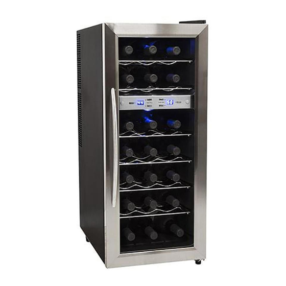
- Page 1 Document Type: Service Manual Version: V1.0 02022018 EdgeStar, 8606 Wall St, Suite 1800, Austin, TX 78754 support.edgestar.com • service@edgestar.com • edgestar.com...
-
Page 2: Table Of Contents
CONTENTS CONTENTS ..........................1 SAFETY PRECAUTIONS ......................1 ELECTRICAL SAFETY ......................2 GENERAL SAFETY ....................... 3 THERMOELECTRIC PRECAUTIONS ..................4 FINDING A GOOD SPOT FOR YOUR WINE COOLER ............. 4 THERMOELECTRIC COOLING PRINCIPLES................5 EXPLODED VIEW DIAGRAM ....................6 PARTS LIST ..........................7 CIRCUIT BOARD DIAGRAM ..................... -
Page 3: Electrical Safety
Electrical Safety Do not exceed the power outlet ratings. It is recommended that the unit be connected to its own circuit. A standard electrical supply (120V, 60Hz), that is properly grounded in accordance with the National Electrical Code and all state and local codes and ordinances is required. ... -
Page 4: General Safety
General Safety Always unplug an appliance from the power supply before attempting any service. Disconnect the power cord by grasping the plug, not the cord. Do not allow children or pets to play on or in the appliance. ... -
Page 5: Thermoelectric Precautions
Thermoelectric Precautions This wine cooler uses thermoelectric technology rather than compression or absorption-types and there are several issues that need attention: Room temperature - The wine cooler needs to be located in a climate controlled room. The unit will perform it’s best at a room temperature of approximately 72° to 77℉. It will not cool correctly when the room temperature is higher than 90°... -
Page 6: Thermoelectric Cooling Principles
Thermoelectric Cooling Principles Thermoelectric cooling, called the Peltier effect, is a solid-state method of cooling or heating by passing current through two different (P shape & N shape) semiconductor materials. The complete system includes a semi-conductor module (P&N shape semi-conductors clamped with two ceramic chips), an internal and external heat exchanger. -
Page 7: Exploded View Diagram
Exploded View Diagram... -
Page 8: Parts List
Parts List... -
Page 9: Circuit Board Diagram
Circuit Board Diagram... -
Page 10: Specifications
Specifications Model TWR215ESS Voltage/frequency 115V/60Hz 140 W (77℉) Power 2.0 A (77℉) Rated Current Net Weight 45.2 Pounds Note: Specifications are subject to change. Check the rating label on the back of unit for the most accurate information Wiring Diagram... -
Page 11: Power Supply Board
Power Supply Board Connector Arrangement NOTE: All wiring connections need to be attached securely to the board. Replacing the Power Supply Board After removing the rear cover, disconnect the wire connectors on the Power Supply Board. - Page 12 Remove screws (4) from the board, desolder the wires (4) from the thermoelectric module. Replace the PCB and reattach the screws(4) Reconnect the connectors on the PCB and resolder the wires from the thermoelectric module.
-
Page 13: Replacing Temperature Control Board
Replacing Temperature Control Board Use a razor blade to pry out the left and right caps Remove screws(2) on the control panel Disassemble the temperature control box after removing the screws (2) on the temperature box. - Page 14 Pull out the temperature board and disconnect the wire connector. Replace with new temperature control board. Reconnect the wire connector and reassemble the control panel.
-
Page 15: Thermoelectric Module And Fans
Thermoelectric Module and Fans... -
Page 16: Replacing Thermoelectric Module And Fans
Replacing Thermoelectric Module and Fans Disconnect the wire connectors from the Power Control Board and Temperature Control Board. Remove the screws (2) on the Thermoelectric Module. Pull out the module and the connector for the cooling fan. - Page 17 When replacing the heating fan pay attention to the direction of the fan and it’s wiring. When replacing the cooling fan pay attention to the direction of the fan and it’s wiring.
- Page 18 When reconnecting the cooling fan make sure to align the bracket in the proper position and reattach the screws (2) to the module. Reconnect the wires to the power control board.
-
Page 19: Replacing The Thermoelectric Node
Replacing the Thermoelectric Node Remove the screws and the components of heating and cooling fan Remove screws (2) on the cool sink Remove the thermoelectric node. - Page 20 When replacing the thermoelectric node make sure it faces the correct direction and apply thermal grease evenly. Reassemble thermoelectric module.
-
Page 21: Diagnostic Flow: Wine Cooler Does Not Cool Or Will Not Run
Diagnostic Flow: Wine cooler does not cool or will not °... - Page 22 EdgeStar, 8606 Wall St, Suite 1800, Austin, TX 78754 support.edgestar.com • service@edgestar.com • edgestar.com...
Need help?
Do you have a question about the TWR215ESS and is the answer not in the manual?
Questions and answers