Table of Contents
Advertisement
Quick Links
Advertisement
Table of Contents
Troubleshooting

Related Manuals for Yamaha GRIZZLY 350 YFM35GW


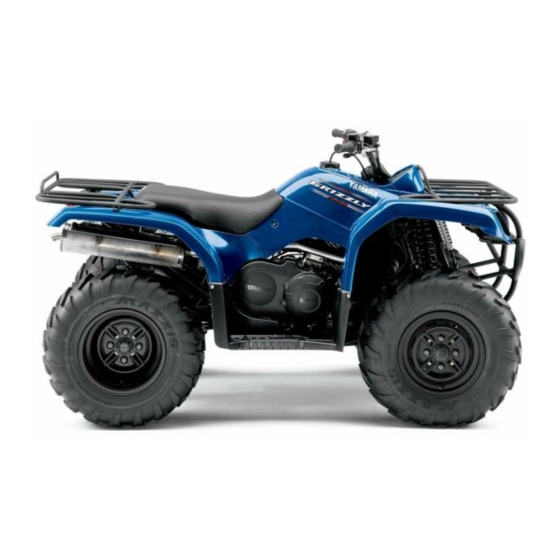
Summary of Contents for Yamaha GRIZZLY 350 YFM35GW
- Page 1 OWNER’S MANUAL MANUEL DU PROPRIÉTAIRE MANUAL DEL PROPIETARIO YFM35GW 5WH-F8199-63...
- Page 2 YAMAHA MOTOR CO., LTD. PRINTED IN USA 2006.05-0.3×2 CR (E,F,S)
- Page 3 OWNER’S MANUAL YFM35GW 5WH-F8199-63-E0...
- Page 4 EC Declaration of Conformity conforming to Directive 98/37/EC YAMAHA MOTOR EUROPE N.V., (Name of supplier) Koolhovenlaan 101, 1119 NC Schiphol-Rijk, The Netherlands, representing YAMAHA MOTOR MANUFACTURING CORPORATION OF AMERICA, Newnan, Georgia, U.S.A., declare in sole responsibility, that the product YFM350A (5Y4AH10W050500001~) (Make, model)
- Page 5 Yamaha experience in the production of fine sporting, touring, and pacesetting racing machines. With the purchase of this Yamaha, you can now appreciate the high degree of craftsmanship and reliability that have made Yamaha a leader in these fields.
- Page 6 EBU17330 IMPORTANT MANUAL INFORMATION EBU17341 FAILURE TO FOLLOW THE WARNINGS CONTAINED IN THIS MANUAL CAN RESULT IN SERIOUS IN- JURY OR DEATH. Particularly important information is distinguished in this manual by the following notations: The Safety Alert Symbol means ATTENTION! BECOME ALERT! YOUR SAFETY IS INVOLVED! Failure to follow WARNING instructions could result in severe injury or death to the ATV operator, a bystander, or a person inspecting or...
- Page 7 IMPORTANT NOTICE EBU17370 Welcome to the Yamaha world of motor sports! This ATV is designed and manufactured for use on UNPAVED surfaces only. It is unsafe to operate this ATV on any paved surface, paved street, paved road or motorway.
-
Page 8: Table Of Contents
EBU17420 TABLE OF CONTENTS SAFETY INFORMATION ......1-1 Fuel .............4-9 Fuel cock ..........4-10 LOCATION OF THE WARNING AND Starter (choke) ..........4-11 SPECIFICATION LABELS ......2-1 Seat ............4-12 Storage compartment .......4-13 DESCRIPTION ..........3-1 Front carrier ..........4-14 Left view ............3-1 Rear carrier ..........4-14 Right view............ - Page 9 OPERATION ..........6-1 PERIODIC MAINTENANCE AND MINOR Starting a cold engine ........ 6-1 REPAIR ............8-1 Starting a warm engine ......6-3 Owner’s manual and tool kit .......8-1 Operating the drive select lever and Periodic maintenance and lubrication driving in reverse ........6-3 chart ............8-3 Engine break-in ..........
- Page 10 Brake light switches ......... 8-30 SPECIFICATIONS ........10-1 Checking and lubricating the cables ..8-31 Checking and lubricating the front and CONSUMER INFORMATION.......11-1 rear brake levers ........8-31 Identification numbers .......11-1 Checking and lubricating the brake pedal ............8-32 Checking the wheel bearings ....8-32 Lubricating the drive shaft universal joint ............
-
Page 11: Safety Information
EBU17430 SAFETY INFORMATION EBU17562 Never carry a passenger on an ATV. Always avoid operating an ATV on any paved AN ATV IS NOT A TOY AND CAN BE HAZARD- surfaces, including sidewalks, driveways, park- OUS TO OPERATE. ing lots and paved streets. An ATV handles differently from other vehicles, in- Never operate an ATV on any paved street, cluding motorcycles and cars. - Page 12 Always inspect your ATV each time you use it to Always follow proper procedures for climbing make sure it is in safe operating condition. Al- hills as described in this manual. Check the ter- ways follow the inspection and maintenance rain carefully before you start up any hill.
- Page 13 roll backwards, follow the special procedure for Always be sure there are no obstacles or people braking described in this manual. Dismount on behind you when you operate in reverse. When the uphill side or to a side if pointed straight up- it is safe to proceed in reverse, go slowly.
- Page 14 nition such as the pilot lights of water heat- EWB00070 WARNING ers and clothes dryers. Gasoline can catch fire and you could be burned. Always operate your ATV in an area with ade- When transporting the ATV in another vehi- quate ventilation.
-
Page 15: Location Of The Warning And Specification Labels
EBU17660 LOCATION OF THE WARNING AND SPECIFICATION LABELS... - Page 16 Read and understand all of the labels on your ATV. These labels contain important information for safe and proper operation. Never remove any labels from your ATV. If a label becomes difficult to read or comes off, request a replace- ment label from your Yamaha dealer. For Europe and Oceania...
- Page 17 For Europe...
- Page 18 For Europe...
- Page 19 For Oceania...
- Page 20 For Oceania...
-
Page 21: Description
EBU17680 DESCRIPTION EBU17690 EBU17700 Left view Right view 1. Fuel cock 1. Rear shock absorber assembly spring preload adjusting ring 2. Throttle stop screw 2. Spark arrester 3. Air filter case 3. Storage compartment and tool kit 4. Fuses 4. Spark plug 5. -
Page 22: Controls And Instruments
EBU17712 NOTE: Controls and instruments The ATV you have purchased may differ slightly from the figures shown in this manual. 1. Rear brake lever 2. Handlebar switches 3. Starter (choke) 4. Parking brake lock plate 5. Horn switch 6. Drive select lever 7. -
Page 23: Instrument And Control Functions
EBU17730 INSTRUMENT AND CONTROL FUNCTIONS EBU17770 Main switch The positions of the main switch are as follows: All electrical systems are supplied with power. The headlights, meter lighting and taillight come on when the light switch is on, and the engine can be started. -
Page 24: Indicator Lights And Warning Light
If the warning light stays on, allow the engine to 1. Reverse indicator light “REVERSE” cool. If the warning light stays on when the engine 2. Neutral indicator light “NEUTRAL” is cool, have a Yamaha dealer check the electrical 3. Oil temperature warning light “ ” circuit. -
Page 25: Speedometer
EBU18020 EBU18060 Speedometer Handlebar switches The speedometer shows the riding speed. This speedometer is equipped with an odometer and a tripmeter. The tripmeter can be reset to “0” with the reset knob. Use the tripmeter to estimate how far you can ride on a tank of fuel before going to re- serve. -
Page 26: Throttle Lever
EBU18100 EBU18280 Start switch “ ” Throttle lever Push this switch to crank the engine with the start- Once the engine is running, movement of the throt- tle lever will increase the engine speed. ECB00050 Regulate the speed of the ATV by varying the CAUTION: throttle position. -
Page 27: Speed Limiter
This could cause an accident. Check the op- eration of the throttle lever before you start the engine. If the throttle does not work smoothly, check for the cause. Correct the problem be- fore riding the ATV or consult a Yamaha dealer. EBU18321 Speed limiter 1. Locknut 2. -
Page 28: Front Brake Lever
EBU18391 Front brake lever The front brake lever is located on the right handle- bar. To apply the front brake, pull the brake lever toward the handlebar grip. 1. Brake pedal 1. Front brake lever EBU18442 Brake pedal and rear brake lever The brake pedal is located on the right side of the ATV and the rear brake lever is located on the left handlebar. -
Page 29: Parking Brake
EBU18460 Always be sure you have released the park- Parking brake ing brake before you begin to ride. The brake Use the parking brake before starting the engine or could overheat if you ride the ATV without re- parking the ATV, especially on a slope. Apply the leasing the parking brake. -
Page 30: Recoil Starter
1. Drive select lever 1. Recoil starter EWB00340 EBU18670 WARNING Recoil starter Shift the drive select lever into the neutral po- Firmly grasp the handle and pull slightly until en- sition and apply the parking brake before start- gagement can be felt. Then pull forcefully, being ing the engine, otherwise the ATV could start careful not to pull the rope all the way out. -
Page 31: Fuel
1. Fuel tank cap 1. Fuel level 2. Fuel tank filler tube EBU18750 Fuel Recommended fuel: Make sure that there is sufficient fuel in the tank. UNLEADED GASOLINE ONLY Fill the fuel tank to the bottom of the filler tube as For Europe: Regular unleaded gasoline only shown. -
Page 32: Fuel Cock
EBU18820 NOTE: Fuel cock If knocking or pinging occurs, use a different brand The fuel cock supplies fuel from the tank to the car- of gasoline or higher octane grade. buretor while also filtering it. The fuel cock lever positions are explained as fol- ECB00070 lows and shown in the illustrations. -
Page 33: Starter (Choke)
1. Arrow mark pointing to “ON” 1. Arrow mark pointing to “RES” With the fuel cock lever in this position, fuel flows This indicates reserve. With the fuel cock lever in to the carburetor. Turn the fuel cock lever to this this position, the fuel reserve is made available. -
Page 34: Seat
Move the starter (choke) in direction (b) to turn off the starter (choke). See the “Starting a cold engine” section on page 6-1 for proper operation. 1. Seat 2. Seat lock lever To install the seat Insert the projections on the front of the seat into 1. -
Page 35: Storage Compartment
1. Projection 1. Storage compartment 2. Seat holder Do not exceed the load limit of 2.0 kg (4 lb) for the storage compartment. EBU18911 Storage compartment Do not exceed the maximum load of 210.0 kg (463 lb) for the ATV. ECB00130 CAUTION: NOTE:... -
Page 36: Front Carrier
EBU18990 Adjusting the front shock absorber as- semblies The spring preload can be adjusted to suit the rid- er’s weight and the riding conditions. Adjust the spring preload as follows. Turn the adjusting ring in direction (a) to increase the spring preload and thereby harden the suspen- sion, and in direction (b) to decrease the spring preload and thereby soften the suspension. -
Page 37: Adjusting The Rear Shock Absorber Assembly
EWB00400 NOTE: WARNING A special wrench can be obtained at a Yamaha Always adjust the shock absorber assemblies dealer to make this adjustment. on the left and right side to the same setting. Uneven adjustment can cause poor handling and loss of stability, which could lead to an ac- cident. - Page 38 1. Spring preload adjusting ring 1. Special wrench 2. Position indicator Spring preload setting: Minimum (soft): NOTE: A special wrench can be obtained at a Yamaha dealer to make this adjustment. Standard: Maximum (hard): 4-16...
-
Page 39: Pre-Operation Checks
Before operating this ATV, be sure to check the items listed in the following table. NOTE: The maintenance of some items in the table has to be performed by a Yamaha dealer. Refer to the “Periodic maintenance and lubrication chart” on page 8-3 to determine which service should be performed by a Yamaha dealer. - Page 40 ITEM ROUTINE PAGE • Make sure that operation is smooth. Lubricate cable and lever hous- Throttle lever ing if necessary. 5-4, 8-23 • Check cable free play, and adjust if necessary. Control cables • Make sure that operation is smooth. Lubricate if necessary. 8-31 •...
-
Page 41: Fuel
Brake levers and brake pedal (See page 4-9.) Check that there is no free play in the front brake EWB00520 lever. If there is free play, have a Yamaha dealer WARNING check the brake system. Do not overfill the fuel tank. Fuel expands Check for correct free play in the rear brake lever when it heats up. -
Page 42: Throttle Lever
EBU19811 Tires the brake system. If there is any leakage, the brake EWB00591 system should be checked by a Yamaha dealer. WARNING Use of improper tires on this ATV, or operation Brake operation of this ATV with improper or uneven tire pres-... -
Page 43: Measuring The Tire Pressure
Type: Rear: Tubeless 250 kPa (36 psi) (2.5 kgf/cm²) The tires should be set to the recommended Higher pressures and fast inflation may pressure: cause a tire to burst. Inflate the tires very Recommended tire pressure: slowly and carefully. Front: 25.0 kPa (3.6 psi) (0.250 kgf/cm²) EBU19820 Measuring the tire pressure... -
Page 44: Tire Wear Limit
Recommended pressure: Front 25.0 kPa (3.6 psi) (0.250 kgf/cm²) Rear 25.0 kPa (3.6 psi) (0.250 kgf/cm²) Minimum: Front 22.0 kPa (3.2 psi) (0.220 kgf/cm²) Rear 22.0 kPa (3.2 psi) (0.220 kgf/cm²) Maximum: 1. Low-pressure tire gauge Front 28.0 kPa (4.1 psi) (0.280 kgf/cm²) Set the tire pressure when the tires are cold. -
Page 45: Chassis Fasteners
1. Tire wear limit EBU19840 Chassis fasteners Make sure that all nuts, bolts and screws are prop- erly tightened. EBU19850 Instruments, lights and switches Check that all instruments, lights and switches are working properly. Correct if necessary. -
Page 46: Operation
4. Shift the drive select lever into the neutral po- accident or injury. If there is a control or func- sition. The neutral indicator light should come tion you do not understand, ask your Yamaha on. If the indicator light does not come on, dealer. - Page 47 5. Use the starter (choke) in reference to the fig- 6. Completely close the throttle lever and start ure: the engine by pushing the start switch. Position (1): NOTE: Cold engine start with ambient temperature If the engine fails to start, release the start below 5 °C (40 °F).
-
Page 48: Starting A Warm Engine
NOTE: NOTE: The engine is warm when it responds normally to Make sure that the drive select lever is completely the throttle with the starter (choke) turned off. shifted into position. EBU20291 Starting a warm engine Follow the same procedure as for starting a cold engine, with the exception that the starter (choke) is not required when the engine is warm. -
Page 49: Engine Break-In
If the indicator light does not come on, resulting in serious injury. When you shift into have a Yamaha dealer check the electrical circuit. reverse, make sure there are no people or ob- stacles behind you. When it is safe to proceed, go slowly. -
Page 50: Parking
If any engine trouble should occur during the EWB00830 engine break-in period, immediately have a WARNING Yamaha dealer check the ATV. Avoid parking on hills or other inclines. Park- ing on a hill or other incline could cause the EBU20700... -
Page 51: Accessories And Loading
ATV. Your Yamaha dealer has a variety of gen- uine Yamaha accessories. Other accessories may also be available on the market. However, it is not possible for Yamaha to test all non- Yamaha accessories, nor control over their qual- ity or suitability. Choose a genuine Yamaha ac- cessory, or one that is equivalent in design and quality. - Page 52 could make steering difficult, an accessory that MAXIMUM LOADING LIMIT limits your ability to move around on the seat, or ATV loading limit (total weight of rider, cargo, one that limits your view. accessories, and tongue): Use extra caution when riding an ATV with ac- 210.0 kg (463 lb) cessories.
- Page 53 Load cargo on the carriers as close to the center curely attached. Reduce speed when carrying of the ATV as possible. Put cargo at the rear of cargo or pulling a trailer. Allow greater dis- the front carrier, at the front of the rear carrier, tance for braking.
-
Page 54: Riding Your Atv
EBU21141 RIDING YOUR ATV... -
Page 55: Getting To Know Your Atv
EBU21631 RIDE WITH CARE AND GOOD JUDGEMENT Get training if you are inexperienced. GETTING TO KNOW YOUR ATV Beginners should get training from a certified in- This ATV is for recreation and utility use. This sec- structor. tion, Riding your ATV, provides general ATV riding Become familiar with this ATV at slow speeds first, instructions for recreational riding. - Page 56 Not recommended for children under 16 years This ATV is designed to carry operator and car- of age. go only – passengers prohibited. EWB01390 EWB01400 WARNING WARNING A child under 16 should never operate an ATV Never carry a passenger. The long seat is to al- with engine size greater than 90 cc.
- Page 57 Apparel Always wear an approved motorcycle helmet that fits properly. You should also wear: eye protection (goggles or face shield) gloves boots long-sleeved shirt or jacket long pants 1. Protective clothing 2. Goggles 3. Gloves 4. Boots 5. Helmet...
- Page 58 EWB01410 WARNING Never operate this ATV without wearing an ap- proved motorcycle helmet, eye protection and protective clothing. Operating without an ap- proved motorcycle helmet increases your chances of a severe head injury or death in the event of an accident. Operating without eye protection can result in an accident and in- creases your chances of a severe injury in the event of an accident.
- Page 59 in the Owner’s Manual. Failure to inspect the Speed limiter ATV before operating or failure to properly For riders less experienced with this model, the maintain the ATV increases the possibility of throttle lever housing is equipped with a speed lim- an accident or equipment damage.
- Page 60 Loading and accessories EWB01460 WARNING Use extra caution when riding the ATV with addi- tional loads, such as accessories or cargo. The Never exceed the stated load capacity for ATV’s handling may be adversely affected. Re- this ATV. duce your speed when adding additional loads. Cargo should be properly distributed and se- curely attached.
- Page 61 All parts and tact with the rear wheels, which could injure accessories added to this ATV should be gen- you or cause an accident. uine Yamaha or equivalent components de- signed for use on this ATV and should be...
-
Page 62: Be Careful Where You Ride
installed and used according to instructions. Improper installation of accessories or modifi- cation of this ATV may cause changes in han- dling which in some situations could lead to an accident. If you have questions, consult an au- thorized ATV dealer. Exhaust system The exhaust system on the ATV is very hot during and following operation. - Page 63 EWB01520 WARNING Never operate this ATV on any paved street, paved road or motorway. You can collide with another vehicle. In many areas, it is illegal to operate ATVs on public streets, roads and highways. While riding on unpaved public streets or roads may be legal in your area, such operation can in- crease the risk of collision with other vehicles.
- Page 64 EWB01530 ATV on such terrain. Failure to use extra care WARNING when operating on excessively rough, slippery or loose terrain could cause loss of traction or Go slowly and be extra careful when operating ATV control, which could result in an accident, on unfamiliar terrain.
- Page 65 Select a large, flat, unpaved area to become famil- iar with your ATV. Make sure that this area is free of obstacles and other riders. You should practice EWB01550 control of the throttle, brakes, and turning tech- WARNING niques in this area before trying more difficult ter- Always mount a caution flag on the ATV to rain.
-
Page 66: Turning Your Atv
With the engine idling, return the starter (choke) to EWB01570 WARNING the closed position and shift the drive select lever into the forward position, then release the parking Always follow proper procedures for turning brake. Apply the throttle slowly and smoothly. The as described in this Owner’s Manual. -
Page 67: Climbing Uphill
Improper riding procedures such as abrupt throttle changes, excessive braking, incorrect body move- ments, or too much speed for the sharpness of the turn may cause the ATV to tip. If the ATV begins to tip over to the outside while negotiating a turn, lean more to the inside. - Page 68 EWB01580 Never go over the top of any hill at high WARNING speed. An obstacle, a sharp drop, or another vehicle or person could be on the other side Never operate the ATV on hills too steep for the of the hill. ATV or for your abilities.
- Page 69 EWB01600 WARNING Never attempt to turn the ATV around on any hill until you have mastered the turning tech- nique as described in the Owner’s Manual on level ground. Be very careful when turning on any hill. Avoid crossing the side of a steep hill if possible.
-
Page 70: Riding Downhill
EWB01741 WARNING Maintain a steady speed when climbing a hill. If you lose all forward speed: Keep weight uphill. Apply the brakes. Apply the parking brake after you are stopped. If you begin rolling backwards: Keep weight uphill. Never apply the rear brake while rolling backwards. -
Page 71: Crossing A Slope
Whenever possible, ride your ATV straight down- hill. Avoid sharp angles which could allow the ATV to tip or roll over. Carefully choose your path and ride no faster than you will be able to react to ob- stacles which may appear. EWB01620 WARNING Always follow proper procedures for going... -
Page 72: Crossing Through Shallow Water
the front wheels slightly uphill. When riding on slopes, be sure not to make sharp turns either up or down hill. If your ATV does begin to tip over, gradually steer in the downhill direction if there are no obstacles in your path. - Page 73 EWB01640 Test your brakes after leaving the water. Do not WARNING continue to ride your ATV without verifying that you have regained proper braking ability. Never operate this ATV in fast flowing water or in water deeper than that specified in your Owner’s Manual.
- Page 74 plug to drain any water that may have accumu- lated. Wash the ATV in fresh water if it has been operated in salt water or muddy conditions. 1. V-belt cooling duct check hose (left front side of ATV) 1. Air filter case check hose 1.
-
Page 75: Riding Over Rough Terrain
RIDING OVER ROUGH TERRAIN Riding over rough terrain should be done with cau- tion. Look out for obstacles which could cause damage to the ATV or could lead to an upset or ac- cident. Be sure to keep your feet firmly mounted on the footboards at all times. - Page 76 If the rear wheels of your ATV start to slide side- ways, control can usually be regained (if there is With practice, over a period of time, skill at con- room to do so) by steering in the direction of the trolled sliding can be developed.
-
Page 77: What To Do If
On extremely slippery surfaces, such as ice, If your ATV can’t make it up a hill you are trying go slowly and be very cautious in order to re- to climb: duce the chance of skidding or sliding out of Turn the ATV around if you still have forward control. -
Page 78: Periodic Maintenance And Minor Repair
EBU21653 PERIODIC MAINTENANCE AND MINOR REPAIR EBU21670 otherwise specified. Have a Yamaha dealer perform the service if you are not familiar with Safety is an obligation of the owner. Periodic in- maintenance work. spection, adjustment and lubrication will keep your... - Page 79 NOTE: If you do not have the tools or experience required for a particular job, have a Yamaha dealer perform it for you. EWB01850 WARNING Never modify this ATV through improper in-...
-
Page 80: Periodic Maintenance And Lubrication Chart
However, keep in mind that if the ATV isn’t used for a long period of time, the month maintenance intervals should be followed. Items marked with an asterisk should be performed by a Yamaha dealer as they require special tools, data and technical skills. - Page 81 INITIAL EVERY month Whichev- CHECK OR MAINTENANCE ITEM er comes 1200 2400 2400 4800 first (mi) (200) (750) (1500) (1500) (3000) hours • Check operation and correct if necessary. √ √ √ √ √ • Check brake lever and pedal free play, and adjust Rear brake if necessary.
- Page 82 INITIAL EVERY month Whichev- CHECK OR MAINTENANCE ITEM er comes 1200 2400 2400 4800 first (mi) (200) (750) (1500) (1500) (3000) hours Shock absorber as- • Check operation and correct if necessary. √ √ √ semblies • Check for oil leakage and replace if necessary. √...
- Page 83 INITIAL EVERY month Whichev- CHECK OR MAINTENANCE ITEM er comes 1200 2400 2400 4800 first (mi) (200) (750) (1500) (1500) (3000) hours Drive select lever • Check operation and adjust or replace if neces- √ √ √ 27 * safety system cable sary.
- Page 84 • Every two years replace the internal components of the brake master cylinders and calipers, and change the brake fluid. • Replace the brake hoses every four years and if cracked or damaged.
-
Page 85: Removing And Installing The Panel
EBU23080 Removing and installing the panel The panel shown needs to be removed to perform some of the maintenance jobs described in this chapter. Refer to this section each time the panel needs to be removed and installed. 1. Panel A 2. - Page 86 Do not kit. attempt to diagnose such problems yourself. In- stead, have a Yamaha dealer check the ATV. 2. Check the spark plug for electrode erosion and excessive carbon or other deposits, and replace it if necessary.
-
Page 87: Engine Oil And Oil Filter Cartridge
3. Install the spark plug with the spark plug Specified spark plug: wrench, and then tighten it to the specified NGK/DR8EA torque. To install the spark plug Tightening torque: 1. Measure the spark plug gap with a wire thick- Spark plug: ness gauge and, if necessary, adjust the gap 17.5 Nm (1.75 m·kgf, 12.7 ft·lbf) to specification. - Page 88 2. Start the engine, warm it up for several min- utes, and then turn it off. 3. Wait a few minutes until the oil settles before checking. 4. Remove the engine oil filler cap, and then wipe the dipstick off with a clean rag. 1.
- Page 89 To change the engine oil (with or without oil fil- 5. Remove the oil filter cartridge with an oil filter ter cartridge replacement) wrench. 1. Place the ATV on a level surface. 2. Start the engine, warm it up for several min- utes, and then turn it off.
- Page 90 NOTE: An oil filter wrench is available at a nearby Yamaha dealer. 6. Apply a thin coat of engine oil to the O-ring of the new oil filter cartridge. NOTE: Make sure that the O-ring is properly seated. 1. Torque wrench...
-
Page 91: Final Gear Oil
If any leakage is found, have Without oil filter cartridge replacement: a Yamaha dealer check and repair the ATV. In ad- 2.20 L (2.33 US qt) (1.94 Imp.qt) dition, the final gear oil level must be checked and... - Page 92 To change the final gear oil 1. Remove the final gear case guard by remov- ing the bolts. 1. Final gear oil 2. Final gear oil filler bolt 3. Correct oil level 1. Final gear case guard 3. If the oil is below the brim of the filler hole, add 2.
- Page 93 1. Final gear oil drain bolt 1. Final gear oil 2. Final gear oil filler bolt 5. Install the drain bolt, and then tighten it to the 3. Correct oil level specified torque. Recommended final gear oil: Tightening torque: See page 10-1. Final gear oil drain bolt: 23 Nm (2.3 m·kgf, 17 ft·lbf) ECB00420...
-
Page 94: Cleaning The Air Filter Element
Tightening torque: NOTE: Final gear oil filler bolt: There is a check hose at the bottom of the air filter 23 Nm (2.3 m·kgf, 17 ft·lbf) case. If dust or water collects in this hose, empty the hose and clean the air filter element and air fil- 8. - Page 95 1. Air filter case holder 1. Air filter element 2. Air filter case cover 4. Pull off the lock plate, and then remove the 3. Pull the air filter element out of the air filter sponge material from the air filter element case.
- Page 96 ECB00440 CAUTION: Do not twist the sponge material when squeez- ing it. 7. Check the sponge material and replace it if damaged. 8. Apply a quality foam air filter oil to the sponge material. NOTE: The sponge material should be wet but not drip- ping.
-
Page 97: Cleaning The Spark Arrester
manifold fittings for an air-tight seal. Tighten all fit- tings securely to avoid the possibility of unfiltered air entering the engine. ECB00460 CAUTION: Make sure that the air filter element is prop- erly seated in the air filter case. Never operate the engine with the air filter el- ement removed. -
Page 98: V-Belt Cooling Duct Check Hose
NOTE: Always let the exhaust system cool prior to If water drains from the V-belt case after removing touching exhaust components. the plug, have a Yamaha dealer check the ATV as the water may affect other engine parts. 8-21... -
Page 99: Adjusting The Carburetor
ECB00480 CAUTION: The carburetor has been set and extensively tested at the Yamaha factory. Changing these settings without sufficient technical knowl- edge may result in poor performance of or damage to the engine. EBU24000 Adjusting the engine idling speed The engine idling speed must be checked and, if necessary, adjusted as follows at the intervals 1. -
Page 100: Adjusting The Throttle Cable Free Play
(a). To decrease 1450–1550 r/min the throttle cable free play, turn the adjusting bolt in direction (b). NOTE: If the specified idling speed cannot be obtained as described above, have a Yamaha dealer make the adjustment. 8-23... -
Page 101: Valve Clearance
1.0 mm prevent this from occurring, the valve clearance (0.04 in), have a Yamaha dealer replace the brake must be adjusted by a Yamaha dealer at the inter- pads as a set. vals specified in the periodic maintenance and lu- brication chart. -
Page 102: Checking The Brake Fluid Level
Yamaha dealer replace the brake shoes as a set. 1. Brake pad 2. Lining thickness NOTE: 1. Wear limit line The wheels need to be removed to check the 2. -
Page 103: Changing The Brake Fluid
Changing the brake fluid Observe these precautions: When checking the fluid level, make sure that Have a Yamaha dealer change the brake fluid at the top of the brake fluid reservoir is level. the intervals specified in the NOTE after the peri- Use only the recommended quality brake fluid, odic maintenance and lubrication chart. -
Page 104: Checking The Front Brake Lever Free Play
(zero in) as shown. If the free Replacement of brake components requires play is incorrect, have a Yamaha dealer check the professional knowledge. These procedures brake system. should be performed by a Yamaha dealer. - Page 105 Adjusting the brake pedal free play The brake pedal free play should measure 20.0– 30.0 mm (0.79–1.18 in) as shown. If the free play is incorrect, adjust it as follows. 1. Brake pedal free play adjusting nut 2. Brake lever free play adjusting nut Adjusting the brake lever free play The brake lever free play should measure 3.0–5.0 1.
- Page 106 1. Brake lever free play 1. Brake lever free play adjusting nut 2. Locknut 2. Gap “A” 3. Brake lever free play adjusting bolt 3. Turn the brake lever free play adjusting bolt at 1. Loosen the locknut at the brake lever and fully the brake lever in direction (a) to increase the turn in the brake lever free play adjusting bolt.
-
Page 107: Brake Light Switches
4. Tighten the locknut at the brake lever. adjusted as follows, but the other brake light NOTE: switches should be adjusted by a Yamaha dealer. When adjusting the rear brake lever free play: 1. Remove panel A. (See page 8-8.) Be sure not to step on the brake pedal. -
Page 108: Checking And Lubricating The Cables
If a cable is damaged or does not move smoothly, have a Yamaha dealer check or replace Recommended lubricant: Engine oil 8-31... -
Page 109: Checking And Lubricating The Brake Pedal
Yamaha dealer check the wheel bearings. NOTE: To access the brake pedal pivot, remove panel A. -
Page 110: Lubricating The Upper And Lower Arm Pivots
EBU25100 Recommended lubricant: Lubricating the steering shaft Lithium-soap-based grease The steering shaft must be lubricated at the inter- vals specified in the periodic maintenance and lu- EBU25040 brication chart. Lubricating the upper and lower arm pivots Recommended lubricant: The upper and lower arm pivots must be lubricated Lithium-soap-based grease at the intervals specified in the periodic mainte- nance and lubrication chart. - Page 111 KEEP OUT OF REACH OF CHILDREN. To charge the battery Have a Yamaha dealer charge the battery as soon as possible if it seems to have discharged. Keep in mind that the battery tends to discharge more quickly if the ATV is equipped with optional electri- cal accessories.
-
Page 112: Replacing A Fuse
To charge a sealed-type (MF) battery, a spe- cial constant-voltage battery charger is re- quired. Using a conventional battery charger will damage the battery. If you do not have access to a constant-voltage battery charg- er, have a Yamaha dealer charge your bat- tery. 8-35... - Page 113 3. Turn the key to “ON” and turn on the electrical To prevent accidental short-circuiting, turn off circuits to check if the devices operate. the main switch when checking or replacing a 4. If the fuse immediately blows again, have a fuse. Yamaha dealer check the electrical system. 8-36...
-
Page 114: Replacing A Headlight Bulb
EBU26902 Replacing a headlight bulb If a headlight bulb burns out, replace it as follows. 1. Remove the bulb holder cover at the rear of the headlight by pulling it off. 1. Headlight coupler 3. Remove the headlight bulb holder assembly by turning it counterclockwise. - Page 115 NOTE: The headlight bulb cannot be removed from the headlight bulb holder. To replace the headlight bulb, replace the headlight bulb holder assembly. EWB02220 WARNING A headlight bulb is hot when it is on and imme- diately after it is turned off. Wait for the bulb to cool before touching or removing it.
-
Page 116: Adjusting A Headlight Beam
7. Adjust the headlight beam if necessary. EBU25550 Adjusting a headlight beam ECB00690 CAUTION: It is advisable to have a Yamaha dealer make 1. Headlight beam adjusting screw this adjustment. EBU25580 Replacing the tail/brake light bulb To raise a headlight beam, turn the adjusting screw in direction (a). -
Page 117: Installing A Wheel
Tapered nuts are used for both the front and rear wheels. Install the nuts with their tapered side to- wards the wheel. 1. Wheel nut 2. Elevate the ATV and place a suitable stand under the frame. 3. Remove the nuts from the wheel. 1. -
Page 118: Troubleshooting
The following troubleshooting chart represents a quick and easy procedure for checking these vital systems yourself. However, should your ATV re- quire any repair, take it to a Yamaha dealer, whose skilled technicians have the necessary tools, expe- 1. Tapered nut rience, and know-how to service the ATV properly. -
Page 119: Troubleshooting Chart
Remove the spark plug and check the electrodes. The engine does not start. Have a Yamaha dealer check the ATV. Check the battery. 4. Battery The engine turns over The battery is good. -
Page 120: Cleaning And Storage
EBU25860 CLEANING AND STORAGE EBU25880 ed from improper high-pressure detergent Cleaning applications such as those available in coin- Frequent, thorough cleaning of your ATV will not operated car washers. only enhance its appearance but will improve its 4. Once most of the dirt has been hosed off, general performance and extend the useful life of wash all surfaces with warm water and mild, many components. -
Page 121: Storage
EWB02310 Long-term WARNING Before storing your ATV for several months: 1. Follow all the instructions in the “Cleaning” Wet brakes may have reduced stopping ability, section of this chapter. increasing the chance of an accident. Test the brakes after washing. Apply the brakes several 2. - Page 122 c. Install the spark plug cap onto the spark °F) or more than 30 °C (90 °F)]. For more in- plug, and then place the spark plug on the formation on storing the battery, see page cylinder head so that the electrodes are 8-33.
-
Page 123: Specifications
EBU25960 SPECIFICATIONS Dimensions: Engine: Overall length: Engine type: 1984 mm (78.1 in) Air cooled 4-stroke, SOHC Overall width: Cylinder arrangement: 1085 mm (42.7 in) Forward-inclined single cylinder Overall height: Displacement: 1120 mm (44.1 in) 348.0 cm³ Bore × stroke: Seat height: 83.0 ×... - Page 124 Engine oil: Air filter: Type: Air filter element: SAE5W30 or SAE10W30 or SAE10W40 or SAE15W40 Wet element or SAE20W40 or SAE20W50 Fuel: Recommended fuel: 40˚ 50˚C -20˚ -10˚ 0˚ 10˚ 20˚ 30˚ Regular unleaded gasoline only (EUR)(GBR) Unleaded gasoline only (AUS)(NZL) Fuel tank capacity: 5W/30 13.5 L (3.57 US gal) (2.97 Imp.gal)
- Page 125 Transmission type: Loading: V-belt automatic Maximum loading limit: Operation: 210.0 kg (463 lb) Left hand operation (Total weight of rider, cargo, accessories, and tongue) Forward gear: Tire air pressure (measured on cold tires): 35/20 (1.750) Recommended: Reverse gear: Front: 26/15 (1.733) 25.0 kPa (3.6 psi) (0.250 kgf/cm²) Chassis: Rear:...
- Page 126 Front brake: Battery: Type: Model: Dual disc brake YTX14AH Operation: Voltage, capacity: Right hand operation 12 V, 12.0 Ah Recommended fluid: Headlight: DOT 4 Bulb type: Rear brake: Halogen bulb Type: Bulb voltage, wattage x quantity: Drum brake Headlight: 12 V, 30.0/30.0 W × 2 Operation: Left hand and right foot operation Tail/brake light:...
- Page 127 Auxiliary DC jack fuse: 10.0 A 10-5...
-
Page 128: Consumer Information
Yamaha dealer or for ref- erence in case the ATV is stolen. KEY IDENTIFICATION NUMBER: VEHICLE IDENTIFICATION NUMBER: 1. - Page 129 EBU26050 Model label The model label is affixed at the location in the il- lustration. Record the information on this label in the space provided. This information will be need- ed when ordering spare parts from a Yamaha deal- 11-2...
- Page 130 1. Model label 11-3...
- Page 131 INDEX Drive shaft universal joint, lubricating ......8-32 Accessories and loading ..........6-6 Air filter element, cleaning ..........8-17 Engine break-in .............. 6-4 Engine, cold start ............6-1 Engine idling speed ............8-22 Battery ................8-33 Engine oil ............... 5-3 Brake fluid, changing ............
- Page 132 Speedometer ..............4-3 Starter (choke) ............. 4-11 Label locations ............... 2-1 Start switch ..............4-4 Light switch ..............4-4 Steering shaft, lubricating ..........8-33 Storage ................9-2 Main switch ..............4-1 Storage compartment ..........4-13 Model label ..............11-2 Suspension, lubricating the upper and lower arm pivots .................
- Page 134 YAMAHA MOTOR CO., LTD. PRINTED IN USA 2006.05-0.3×2 CR...