Crestron Isys TPS-6000 Operation Manual
15 inch tilt touchpanel
Hide thumbs
Also See for Isys TPS-6000:
- Specification sheet (2 pages) ,
- Installation manual (16 pages) ,
- Field service manual (12 pages)
Table of Contents
Advertisement
Quick Links
Advertisement
Table of Contents

Related Manuals for Crestron Isys TPS-6000


Summary of Contents for Crestron Isys TPS-6000
- Page 1 Crestron Isys™ TPS-6000 15 Inch Tilt Touchpanel Operations Guide...
- Page 2 This document was prepared and written by the Technical Documentation department at: Crestron Electronics, Inc. 15 Volvo Drive Rockleigh, NJ 07647 1-888-CRESTRON All brand names, product names and trademarks are the property of their respective owners. ©2003 Crestron Electronics, Inc.
-
Page 3: Table Of Contents
Crestron Isys™ TPS-6000 Contents 15 Inch Tilt Touchpanel: Crestron Isys™ TPS-6000 Introduction ... 1 Features and Functions ... 1 Specifications ... 3 Physical Description... 5 Position Lock Buttons ... 7 Industry Compliance ... 9 Setup ... 9 Network Wiring... 9 Identity Code ... -
Page 5: Inch Tilt Touchpanel: Crestron Isys™ Tps-6000
Crestron Isys™ TPS-6000 Introduction Features and Functions The TPS-6000 packs all the power and performance of an Isys panel in a stylish tilt model. These units are suitable for tabletop mounting in any Crestron system (herein referred to as the Cresnet room or home theater. - Page 6 15 Inch Tilt Touchpanel TPS-6000 Functional Summary (continued) Multiple graphics can be displayed on the TPS-6000 without any shift in color depth or quality. The touchpanel can support real-time video with the optional TPS-VID-1 or TPS-VID-2 cards, RGB computer graphics with the optional TPS-XVGA RGB Interface card, and 10/100 BaseT TCP/IP network communications with the optional TPS-ENET Ethernet module.
-
Page 7: Specifications
Crestron Isys™ TPS-6000 Specifications The following provides a summary of specifications for the TPS-6000 touchpanel. Specifications for the TPS-6000 Touchpanel (continued on next page) Operations Guide - DOC. 5864A SPECIFICATION Power Requirements 24 Watts (1 Amp @ 24 VDC) (without cards) - Page 8 These control systems do not support loading of firmware or VT Pro-e files to the TPS-series panels through the RS-232 port of the control system. In order to load these files to the TPS-6000 when using these control systems, use the RS-232 port on the TPS-6000 or use a direct Ethernet connection to the panel (assuming the TPS-ENET is installed).
-
Page 9: Physical Description
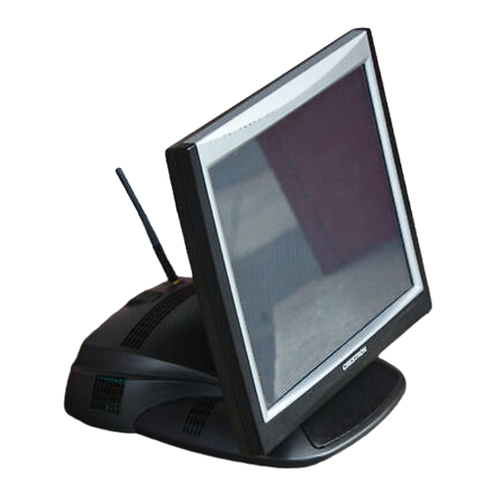
Physical Description The TPS-6000’s 15-inch (38.1-cm) touch sensitive viewing screen is located on the front of the TPS-6000 touchpanel. The electronic hardware is housed in a high impact, black molded plastic enclosure, shown in the following diagram. This touchpanel is designed for placement on a counter. It possesses a hinged base, which can tilt from 30 to 80 degrees. -
Page 10: Expansion Slots
Each card has a specific function and is sold separately. Installation instructions are provided with each card. The available cards for the TPS-6000 are: NOTE: The three cards are NOT interchangeable and can only be installed in their dedicated expansion slots. -
Page 11: Interface Modules
Crestron Isys™ TPS-6000 Memory The TPS-6000 ships with 8MB of flash and 8MB of DRAM. Additional memory by Crestron can be purchased separately and installed in the field. Refer to the latest revision of the Flash Memory for TPS User Interfaces Installation Guide (Doc. 5927) for an installation procedure. - Page 12 The position lock button can then be held down and the touchscreen can be tilted to a more horizontal position. 8 • 15 Inch Tilt Touchpanel: Crestron Isys™ TPS-6000 Crestron Isys™ TPS-6000 Operations Guide - DOC. 5864A...
-
Page 13: Industry Compliance
NOTE: When installing network wiring, refer to the latest revision of the wiring diagram(s) appropriate to your specific system configuration, available from the Downloads | Product Manuals | Wiring Diagrams section of the Crestron website (www.crestron.com). NOTE: Do not power up system until all wiring is verified. Care should be taken to ensure data (Y, Z) and power (24, G) connections are not crossed. -
Page 14: Identity Code
Configuring the Touchpanel NOTE: The only connection required to configure the touchpanel is power (+24V and Ground). Refer to “Hardware Hookup” on page 19 for details. 10 • 15 Inch Tilt Touchpanel: Crestron Isys™ TPS-6000 RESISTANCE (R) WIRE GAUGE Doubled CAT5 Tripled CAT5 Crestron Isys™... -
Page 15: Calibration Menu
CALIBRATION MENU without saving calibration data, create a calibration error by touching the screen in an area that is opposite from the instructed area. Operations Guide - DOC. 5864A 15 Inch Tilt Touchpanel 15 Inch Tilt Touchpanel: Crestron Isys™ TPS-6000 • 11... -
Page 16: Setup Menu
SIMPL Windows program of the Cresnet system. Matching IDs between touchpanel and SIMPL Windows program is required if data is to be successfully transferred. The Net ID for the TPS-6000 is factory set to 03, and no two devices in the same system can have the same Net ID. - Page 17 TPS-XTXRF Two-Way RF Transceiver Module Operations and Installation Guide (Doc. 5844). NOTE: If the TPS-6000 is to be used without an RF connection, the RF Disabled button must be selected. NOTE: If RF is enabled, the RS-232 communication settings cannot be adjusted.
-
Page 18: Audio Menu
On button is active (red text). An active Key Click Off button disables the feature. NOTE: If key click is enabled on a touchpanel, each press of the touchpanel results in an audible click. It may be desirable to conceal the key click sound for certain buttons (e.g., if the button triggers playing of a WAV file). - Page 19 NOTE: IP settings are necessary only if the TPS-ENET is installed. Serially connect a PC to the TPS-6000 via the RS-232 connector and refer to the details in the latest revision of the TPS-ENET Operations & Installation Guide (Doc. 6016) to configure the IP settings.
- Page 20 The touchpanel is capable of storing 16 VGA formats; the panel is factory set with the presets empty. Select SAVE Menu to open the Preset Menu, as shown below. To...
-
Page 21: Video Menu
Video 2 will be displayed. Selection of a Video button opens the Video Menu from which the user can adjust video settings. The TPS-6000 can have up to four different composite video sources connected to either the 6-pin connector or the BNC connectors on the TPS-IMPC when equipped with the TPS-VID-2. - Page 22 The text color of the selected button is red rather than black. Select the Return button, located at the lower right corner of the Video Menu, after video parameters have been set. 18 • 15 Inch Tilt Touchpanel: Crestron Isys™ TPS-6000 Crestron Isys™ TPS-6000 Operations Guide - DOC. 5864A...
-
Page 23: Diagnostics Menu
The Diagnostics button from the MAIN MENU contains controls for enabling an Ethernet card (if installed) and diagnostic tools. The diagnostic tools should only be used under supervision from a Crestron customer service representative during telephone support. The options available from the DIAGNOSTICS MENU, shown to the left, are numeric in nature and their interpretation is beyond the scope of this manual. - Page 24 Prior to installation, use this port for direct connection between the touchpanel and a PC to load files to a touchpanel without a network connection. In the event that modular cables or an RJ-11 to DB9F adapter is not available, the following table and diagram provide information so that the cable can be fabricated on site.
- Page 25 The end of the cable has a metal shield that is required to protect the equipment. Using non-Crestron cables will result in damage to the product. Other cable lengths are available from Crestron.
-
Page 26: Recommended Cleaning
Installation Guide (Doc. 5867) for details. 24 VDC, 2.0A This female connector is used to supply 24 VDC power to the TPS-6000 from an optional power pack (Crestron model PW-2420RU). If video is to be displayed on the touchpanel, 24 VDC power must be supplied to the TPS-IMPC through either the Cresnet connector or the TPS-IMPCs 24VDC connector. - Page 27 This custom template can then be used by Crestron AppBuilder to create the final project files to be loaded into the panels. Alternatively, VT Pro-e can be used to tweak projects created with Crestron AppBuilder or develop original touchpanel screen designs.
-
Page 28: Programming With The Crestron Appbuilder
Windows This section describes a sample SIMPL Windows program that includes a TPS-6000 touchpanel. A Join Number Remapping (JNR) program can be written to augment the functionality of the touchpanel by making some of the touchpanel’s internal functions available to the SIMPL Windows programmer. -
Page 29: C2Net-Device Slot In Configuration Manager
Expanded PRO2 System Tree C2Net-Device Slot in Configuration Manager To incorporate the TPS-6000 touchpanel into the system, drag the TPS-6000 from the Touchpanels | Touchpanels (Cresnet) folder of the Device Library and drop it in the System Views. The PRO2 system tree displays the touchpanel in slot 9 with a default Net ID of 03 as shown in the following illustration. -
Page 30: Signal Types
TPS-6000 Symbol in Programming Manager Programming Manager is where programmers “program” a Creston control system by assigning signals to symbols. The following diagram shows the TPS-6000 symbol in the SIMPL Windows’ Programming Manager. Detail View of the TPS-6000 in SIMPL Windows’ Programming Manager... - Page 31 TPS-6000 Input/Output Signals The TPS-6000 symbol provides up to 4000 digital input and output joins, 4000 analog input and output joins, and up to 999 serial input joins. The programmer selects the signal types by clicking on the appropriate button at the top of the Symbol Detail view when programming the panel.
-
Page 32: Example Program
Crestron SIMPL Windows Symbol Guide (Doc. 6120), or the on-line help included with SIMPL Windows. Example Program An example program for the TPS-6000 is available from the Crestron FTP site (ftp.crestron.com/Examples). Search for the file TPS- 6000_SIMPL_Windows_example_file_(Doc.5864)_TPS-6000L_(Doc. 5825).smw that contains the example program. -
Page 33: Wav File Audio Messages
(recorded as WAV files). A set of pages, which make up a project, can be designed for each TPS-6000 touchpanel application. Each page contains objects such as custom control graphics, two and three-dimensional buttons, sliders, and digital readouts which allow the user to interface with the control system via join numbers. -
Page 34: Sound Manager
Pre-recorded WAV files for voice prompts and responses are available from Crestron. These files can be stored into and programmed for use in the touchpanel directly or may be edited with the Sound Recorder. For example, the individual files can be combined to create custom messages. - Page 35 2. Each WAV file must have the correct audio format and attributes for the TPS-6000 target type selected in VT Pro-e. The correct audio format is PCM, 8, 11, 16, 22, or 44kHz, mono or stereo, 8 or 16 bit.
-
Page 36: Reserved Join Numbers
System Digital Reserved Join Numbers for TPS-6000 Touchpanels continued on next page 32 • 15 Inch Tilt Touchpanel: Crestron Isys™ TPS-6000 3. Select the Add button to transfer the WAV file to the Sound List table located below the browse field. The audio parameters of the file also appear to the right of the table. - Page 37 Crestron Isys™ TPS-6000 System Digital Reserved Join Numbers for TPS-6000 Touchpanels (continued) System Serial Reserved Join Numbers for TPS-6000 Touchpanels Audio Analog Reserved Join Numbers for TPS-6000 Touchpanels Audio Digital Reserved Join Numbers for TPS-6000 Touchpanels continued on next page Operations Guide - DOC.
- Page 38 15 Inch Tilt Touchpanel Audio Digital Reserved Join Numbers for TPS-6000 Touchpanels (continued) * Audio Defaults: Master 88%, Wav 88%, Line 88%, Key Click 29%, All Audio On, Mic AGC On. Video Analog Reserved Join Numbers for the TPS-6000 Touchpanels...
- Page 39 Crestron Isys™ TPS-6000 Video Digital Reserved Join Numbers for TPS-6000 Touchpanels (continued) Operations Guide - DOC. 5864A JOIN # FUNCTION 1, 2 17108 Video 1 1, 2 17109 Video 1 1, 2 17110 Video 1 1, 2 17111 Video 1 Brightness...
- Page 40 15 Inch Tilt Touchpanel XGA Analog Reserved Join Numbers for TPS-6000 Touchpanels XGA Digital Reserved Join Numbers for TPS-6000 Touchpanels 36 • 15 Inch Tilt Touchpanel: Crestron Isys™ TPS-6000 JOIN # FUNCTION 17000 Gain R 17001 Gain G 17002 Gain B...
-
Page 41: Multibyte International Characters
SIMPL Windows. In other words, you cannot enter Chinese character interspersed with numbers. You can enter Chinese characters or numbers in separate strings. Crestron is scheduling time to fix this in the near future and the release notes for SIMPL Windows will mention it. -
Page 42: Communication Settings
Communication Settings Connection of a PC to the TPS-6000 touchpanel can be direct via the RS-232 port on the touchpanel or through a control system (Cresnet). Both methods of connection provide setup for RS-232 communication. - Page 43 “Port Settings” window are selected as shown after this step. Click the OK button to save the settings and close the window. 15 Inch Tilt Touchpanel: Crestron Isys™ TPS-6000 • 39 15 Inch Tilt Touchpanel...
-
Page 44: Uploading A Simpl Windows Program
.csz for CNX generation with SIMPL+. Upload via Crestron Viewport 40 • 15 Inch Tilt Touchpanel: Crestron Isys™ TPS-6000 4. To verify communication, select Diagnostics | Establish Communications (Find Rack). This should display a window that gives the COM port and baud rate. - Page 45 4. To verify that the program has been transferred successfully, select Diagnostics | Report Program Information or press F7. This should display a window that provides details about the current program loaded into the control system. 15 Inch Tilt Touchpanel: Crestron Isys™ TPS-6000 • 41 15 Inch Tilt Touchpanel...
-
Page 46: Uploading A Vt Pro-E Project
2. As shown after this step, select File Transfer | Send Touchpanel (alternatively, press Alt+T) from the Viewport menu. 3. As shown after this step, select the Net ID of the TPS-6000 touchpanel and then click OK. The “Touch Panel Transfer” window appears (refer to the subsequent graphic). -
Page 47: Firmware Upgrade
“Open” Window Firmware Upgrade A firmware upgrade file has the To take advantage of all the TPS-6000 features, it is important that the unit contains extension .csf. the latest firmware available. Therefore, please check the Crestron website (http://www.crestron.com/downloads/software_updates.asp) for the latest version of firmware. - Page 48 2. As shown after this step, select File Transfer | Update Touchpanel Firmware from the Viewport menu. 3. As shown after this step, select the Net ID of the TPS-6000 touchpanel and then click OK. The “Open” window appears (refer to the subsequent graphic).
-
Page 49: Problem Solving
Crestron Isys™ TPS-6000 Problem Solving Troubleshooting The table after this paragraph provides corrective action for possible trouble situations. If further assistance is required, please contact a Crestron customer service representative. TPS-6000 Touchpanel Troubleshooting Operations Guide - DOC. 5864A TROUBLE POSSIBLE CAUSE(S) -
Page 50: Further Inquiries
Crestron award winning customer service team by calling: You can also log onto the online help section of the Crestron website (www.crestron.com) to ask questions about Crestron products. First-time users will need to establish a user account to fully benefit from all available features. -
Page 51: Appendix A: Rs-232 Protocol
TPS-6000 touchpanels support panel operation via a host computer through the RS-232 port. While in this mode, the touchpanel can be used as a stand-alone controller to a host computer running a third party or custom program. Crestron recommends that the following serial data format is set. - Page 52 2400 baud. Obviously, ramping several objects at once requires a baud rate several times as high. Indirect Text – TPS-6000 touchpanels support a feature that permits the text field in any user-defined button to be altered on the fly in RUN mode. This is accomplished by substituting a text pointer for the text in the button.
-
Page 53: Appendix B: Configuring The Rs-232 Port For Use
Crestron Isys™ TPS-6000 Appendix B: Configuring the RS-232 Port for Use To configure the RS-232 port of the TPS-6000, a local PC that contains a Crestron Viewport is required. The Viewport is one of the development tools that is part of Crestron SIMPL Windows or VT Pro-e software. - Page 54 NOTE: Alternatively, use a Cresnet command from the Viewport (communicating to the control system) to access the setup screens. Verify the Net ID of the TPS-6000 and select Functions | Put Touch Panel into Setup Mode. Enter the Net ID and click OK.
-
Page 55: Software License Agreement
This Agreement may only be modified by a writing signed by an authorized officer of Crestron. Updates may be licensed to You by Crestron with additional or different terms. This is the entire agreement between Crestron and You relating to the Software and it supersedes any prior representations, discussions, undertakings, communications or advertising relating to the Software. - Page 56 “applets” incorporated into the Software), the accompanying media and printed materials, and any copies of the Software are owned by Crestron or its suppliers. The Software is protected by copyright laws and international treaty provisions. Therefore, you must treat the Software like any other copyrighted material, subject to the provisions of this Agreement.
-
Page 57: Return And Warranty Policies
CRESTRON shall not be liable to honor the terms of this warranty if the product has been used in any application other than that for which it was intended, or if it has been subjected to misuse, accidental damage, modification, or improper installation procedures. - Page 58 15 Inch Tilt Touchpanel Crestron Isys™ TPS-6000 This page is intentionally left blank. 54 • 15 Inch Tilt Touchpanel: Crestron Isys™ TPS-6000 Operations Guide - DOC. 5864A...
- Page 59 Crestron Isys™ TPS-6000 15 Inch Tilt Touchpanel This page is intentionally left blank. 15 Inch Tilt Touchpanel: Crestron Isys™ TPS-6000 • 55 Operations Guide - DOC. 5864A...
- Page 60 Crestron Electronics, Inc. Operations Guide – DOC. 5864A 15 Volvo Drive Rockleigh, NJ 07647 10.03 Tel: 888.CRESTRON Fax: 201.767.7576 Specifications subject to www.crestron.com change without notice.
Need help?
Do you have a question about the Isys TPS-6000 and is the answer not in the manual?
Questions and answers