Table of Contents
Advertisement
Quick Links
CAMERA CONTROL UNIT
IK-CU44A
INFORMATION
This equipment has been tested and found to comply with the limits for a Class A digital device,
pursuant to Part 15 of the FCC Rules. These limits are designed to provide reasonable protection
against harmful interference when the equipment is operated in a commercial environment. This
equipment generates, uses, and can radiate radio frequency energy and, if not installed and used
in accordance with the instruction manual, may cause harmful interference to radio communica-
tions. Operation of this equipment in a residential area is likely to cause harmful interference in
which case the user will be required to correct the interference at his own expense.
USER-INSTALLER CAUTION: Your authority to operate this FCC verified equipment could be
voided if you make changes or modifications not expressly approved by the party responsible for
compliance to Part 15 of the FCC rules.
This Class A digital apparatus meets all requirements of the Canadian Interference Causing Equip-
ment Regulations.
Cet appareil numérique de la classe A respecte toutes les exigences du Règlement sur le matériel
brouilleur du Canada.
INSTRUCTION MANUAL
For Customer Use
Enter below the Serial No.
which is located on the
bottom of the cabinet. Re-
tain this information for fu-
ture reference.
Model No.: IK-CU44A
Serial No.:
1
Advertisement
Table of Contents

Summary of Contents for Toshiba IK-CU44A
- Page 1 Re- tain this information for fu- ture reference. Model No.: IK-CU44A Serial No.: INFORMATION This equipment has been tested and found to comply with the limits for a Class A digital device, pursuant to Part 15 of the FCC Rules.
-
Page 2: Safety Precautions
SAFETY PRECAUTIONS Read the following safety precautions carefully before using this product. These instructions contain valuable information on safe and proper use that will prevent harm and damage to the operator and other persons. Make sure that you fully understand the following details (indications, graphic symbols) before proceeding to the remaining sections in this manual. - Page 3 5. Repairs or modifications made by the user or caused to be made by the user and carried out by an unauthorized third party. 6. Notwithstanding the foregoing, Toshiba’s liabilities shall not, in any circumstances, exceed the purchase price of the product.
-
Page 4: Table Of Contents
TABLE OF CONTENTS SAFETY PRECAUTIONS ................. 2 1. COMPONENTS ....................5 2. SPECIFICATIONS ................... 5 3. NAMES AND FUNCTIONS ................6 4. CONNECTION ....................8 4.1 An Example of Standard Connection ........... 8 4.2 Cautions on Connection ................. 8 4.3 Connection on Back Panel ..............9 4.4 Connector Pin Assignments .............. -
Page 5: Components
1. COMPONENTS (1) Camera control unit .................. 1 (2) Accessories (a) Instruction manual ................1 2. SPECIFICATIONS Specification with camera head (IK-M44H) connected. Power supply DC12V ± 0.5V Power consumption 310 mA Image sensor 1/2 inch IT-CCD Effective pixels Horizontal: 768 pixels, Vertical: 494 pixels Effective image area Horizontal: 6.54 mm, Vertical: 4.89 mm (1/2 inch type) Scanning system... -
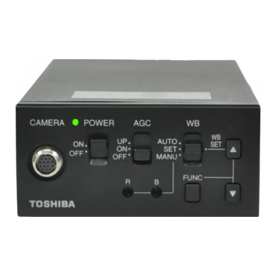
Page 6: Names And Functions
3. NAMES AND FUNCTIONS Camera Control Unit POWER switch AGC switch WB switch POWER indicator CAMERA POWER AUTO UP button MANU CAMERA FUNC terminal DOWN button White balance FUNC button adjust control EXT SYNC S-VIDEO terminal terminal DC IN 12V EXT SYNC S-VIDEO VIDEO... - Page 7 CAMERA terminal Connects to the camera head. POWER switch Turns on and off the camera control unit. POWER indicator Lights up when the power is turned on. AGC switch Selects the gain mode. (AGC OFF/AGC ON/SENS UP) WB switch Selects the white balance mode. (MANU/SET/AUTO) White balance adjust control Adjusts the R gain and B gain with the white balance mode set to MANU by the WB switch...
-
Page 8: Connection
4. CONNECTION 4.1 An Example of Standard Connection Monitor Camera control unit VIDEO Camera Lens head (Option) (Option) CAMERA DC IN 12V Camera cable (Option) DC 12V DC power supply 4.2 Cautions on Connection • When connecting or disconnecting the camera cables (for the camera head and camera control unit), always turn off the power switch of the camera control unit first. -
Page 9: Connection On Back Panel
4.3 Connection on Back Panel The figure below shows the back panel connection terminals of the camera control unit. DC IN 12V EXT SYNC S-VIDEO VIDEO REMOTE IRIS FUNC LOCK 4.4 Connector Pin Assignments DC IN 12V IRIS REMOTE S-VIDEO +12V VIDEO +12V... -
Page 10: When Using The Camera With The Camera Unit Fixed
• EE lens The IRIS extension cable (optional) is usable for the EE lens. Use the connector HR10A- 7P-4P of HIROSE when the IRIS extension cable is selected. For connections, follow the instruction below. When the IRIS extension cable is used under EE lens connector the right condition, the cable automatically HR10A-7P-4P... -
Page 11: Operation
6. OPERATION Turn on the POWER switch on the camera control unit and adjust the lens iris and focus while observing a picture on the monitor screen. To obtain the best picture quality, per- form various settings. 6.1 AGC (Automatic Gain Control) AGC functions “OFF”, “ON”... -
Page 12: White Balance Adjustment In Modes Other Than Auto
(1) White balance adjustment in modes other than AUTO (1.1) White balance adjustment in SET mode Set the WB switch to “SET” position. Shoot a white object to fill entire screen and press the UP button ( ) for about 2 sec. -
Page 13: Mode Setting By On Screen Display
7. MODE SETTING BY ON SCREEN DISPLAY Setting while monitoring the menu on the monitor screen is possible. The following seven items can be set. Scene file Electronic shutter (AUTO/MANUAL), backlight correction Pedestal level Phase matching in external synchronization (horizontal/subcarrier synchronization) White balance, auto electronic shutter, AGC measurement area White balance offset Scene file factory setting... -
Page 14: File (Scene File)
7.1 FILE (Scene File) FILE SHUTTER AUTO There are two scene files A and B which can be se- PEDESTAL lected according to the shooting state. SYNC AREA LINK:1 W B-OFFSET Move the cursor to “FILE” in the main menu us- INIT. -
Page 15: Detail Setting In Auto Mode (Auto Electronic Shutter)
(1) Detail setting in AUTO mode (auto electronic shutter) When the FUNC button is pressed after AUTO is se- AUTO lected, the submenu for SHUTTER:AUTO appears. FILE 1/60 Set details in this screen. SHUTTER 1/100 PEDESTAL 1/250 LEVEL: Adjust the auto electronic shutter SYNC 1/500 video level. -
Page 16: Pedestal
7.3 Pedestal FILE SHUTTER AUTO Move the cursor to PEDESTAL using the UP or PEDESTAL DOWN button. SYNC AREA LINK:1 Press the FUNC button. The cursor moves to the W B-OFFSET data. Set the data using the UP or DOWN button. The data can be set in a range of –50 to +50. -
Page 17: Area (Measurement Area)
Move the cursor to a desired item (H-PHS, SC- PHS, SC-FINE) using the UP or DOWN button. FILE Press the FUNC button and the data is displayed. SHUTTER Set the data using the UP or DOWN button and PEDESTAL press the FUNC button to select the data. To re- SYNC H-PHS turn to the main menu, move the cursor to EXIT... -
Page 18: Setting Area Separately For Agc, Auto Electronic Shutter And White Balance
Press the FUNC button to display data 1 ~ SLIT for LINK. Move the cursor to a desired item of FILE AREA data (1, 1/2, 1/8, SLIT) using the UP or SHUTTER DOWN button. PEDESTAL SYNC Press the FUNC button to set the data. AREA LINK 1 W B-OFFSET... -
Page 19: Wb-Offset (White Balance Offset)
7.6 WB-OFFSET (White Balance Offset) FILE SHUTTER AUTO This offsets the white balance in the direction of PEDESTAL orange or cyan when the WB switch is set to “SET”. SYNC AREA LINK:1 W B-OFFSET Move the cursor to WB-OFFSET using the UP or INIT. -
Page 20: Init. (Scene File Initialization)
7.7 INIT. (Scene File Initialization) FILE SHUTTER AUTO This reset settings of the scene file to the factory PEDESTAL setting. SYNC AREA LINK:1 W B-OFFSET Select a scene file (A or B) to initialize the setting INIT. in FILE. Move the cursor to INIT. using the UP or DOWN button. -
Page 21: External Sync
8. EXTERNAL SYNC When using the camera with external sync, connect a composite video signal (C-VIDEO) to the EXT SYNC terminal on back of the camera control unit. When the camera accepts external sync, it is automatically switched from the internal sync to the external sync. (1) External sync signal input conditions C-VIDEO SYNC section... -
Page 22: Cautions On Use And Installation
9. CAUTIONS ON USE AND INSTALLATION G Carefully handle the units. G Handling of the protection cap. Do not drop, or give a strong shock or vi- Keep the protection cap away from chil- bration to the camera. This may cause dren. -
Page 23: Before Making A Service Call
10. BEFORE MAKING A SERVICE CALL Symptom Items to be checked No picture • Is the power supplied correctly? • Is the lens iris adjusted correctly? • Are the cables connected correctly? Poor color • Is the monitor (TV) adjusted correctly? •... -
Page 24: Exterior Dimensions
12. EXTERIOR DIMENSIONS Unit : mm [inch] Camera Control Unit [6.14] [3.35] 11 [0.43] 7 [0.28] CAMERA POWER AUTO MANU FUNC 10.5 21.5 21.5 [0.41] [0.85] [0.85] [0.79] [1.06] [4.49] DC IN 12V EXT SYNC S-VIDEO VIDEO REMOTE IRIS FUNC LOCK 4-M3 pitch 0.5 Threaded hole φ12... -
Page 25: Servicing Instructions For Service Personnel
Servicing Instructions for Service Personnel 13. Connection to Camera Head (IK-M43H/IK-C43H) When connecting to the camera head (IK-M43H/IK-C43H), select the internal switch inside the camera controller following to the procedures below. 1 After turning off the power, remove all the cables connected to the camera control- ler. - Page 28 [2] You must schedule service within thirty days after you discover a defective product or part. [3] All warranty servicing of this product must be made by a Toshiba ISD Authorized Service Provider. [4] The warranty extends to defects in material or workmanship as limited above, and not to any products or parts that have been lost or discarded by user.