
Related Manuals for ABB OTM_C_21D


Summary of Contents for ABB OTM_C_21D
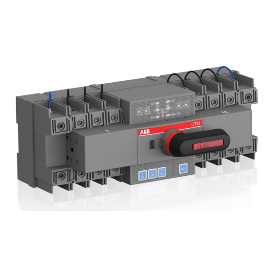
- Page 1 — I N S TA L L AT I O N A N D O P E R AT I N G I N S T R U C T I O N Automatic Transfer Switch OTM_C_21D...
-
Page 2: Table Of Contents
— Table of contents 003 – 004 Symbols & Terms 005 – 008 Product overview 009 – 012 Quick start 013– 016 Interface and Settings Technical data 018 – 020 Installation 021 – 022 Optional accessories Maintenance and common troubleshooting Appendix... -
Page 3: Symbols & Terms
Caution: Provides important information or warns about a situation that may have a detrimental effect on equipment. Information: Provides important information about the equipment. — Explanations of abreviations and terms OTM_C_21D Automatic transfer switch, the type name LN1-Switch I Power supply line, e.g. the primary line LN2-Switch II Power supply line, e.g. -
Page 4: Product Overview
A U T O M AT I C T R A N S F E R S W I T C H , O T M _ C _ 2 1 D — Product overview Product overview The OTM_C_21D automatic transfer switch can be Source transfer can be performed using a manu- used as a source transfer switch in a threephase or ally operated handle, locally using push buttons or single-phase networks. - Page 5 Ts. (if Generator mode is selected) • Change-over switch (Switch I) to the position 0 • Change-over switch (Switch II) to the position II Switch I status Switch II status Figure 2. Automatic Switching Sequences in OTM_C_21D, Line 1 priority...
- Page 6 0 • Change-over switch (Switch I) to the position I Switch I status Switch II status Figure 3. Automatic Switching Sequences in OTM_C_21D, No line priority Generator is disabled in no line priority. Keep generator off in this mode.
- Page 7 Ts (if Generator mode is selected) • Change-over switch (Switch I) to the position 0 • Change-over switch (Switch II) to the position II Switch I status Switch II status Figure 4. Automatic Switching Sequences in OTM_C_21D, Manual back switching mode...
-
Page 8: Quick Start
A U T O M AT I C T R A N S F E R S W I T C H , O T M _ C _ 2 1 D — Quick start To operate the switch manually: 2. - Page 9 2. Automatic operation includes three operating modes: Line 1 priority (factory default setting), No line priority, and manual back switching mode. Figure 6. Selecting the automatic transfer OTM_C_21D switch to Auto Mode System testing Local test In automatic mode, “AUTO” LED is ON and you can transfer the switch using I, O, and II push but- tons on the front panel of the switch.
- Page 10 Position I: Figure 7. Enter test signals; the switch transfers to 2. Ensure that the OTM_C_21D is in automatic Position O à to Position II à to Position O à to mode (“AUTO” LED is on).
- Page 11 A U TO M AT I C T R A N S F E R S W I TC H , OT M _ C _ 2 1 D Locking Locking the electrical operation The switch can be padlocked in any position, causing that all operating modes and test operations are disabled and handle cannot be inserted.
-
Page 12: Interface And Settings
A U T O M AT I C T R A N S F E R S W I T C H , O T M _ C _ 2 1 D — Interface and Settings Buttons Transfer using buttons bypass switching and back switching delays. - Page 13 A U TO M AT I C T R A N S F E R S W I TC H , OT M _ C _ 2 1 D Rotary switch settings 1. Switching delay Ts: The delay of switcing from primary line to secondary line in automatic mode;...
- Page 14 A U T O M AT I C T R A N S F E R S W I T C H , O T M _ C _ 2 1 D Dip switch setting 1. Switching delay Ts: The delay of switcing from primary line to secondary line in automatic mode;...
- Page 15 A U TO M AT I C T R A N S F E R S W I TC H , OT M _ C _ 2 1 D Terminal outputs and inputs The switch has 11 bits of signal terminals for users to input and output signals.
-
Page 16: Technical Data
A U T O M AT I C T R A N S F E R S W I T C H , O T M _ C _ 2 1 D — Technical data Automatic transfer switch Parameters Rated operational voltage Ue [V] 220~240 V AC 50~60 Hz Operating voltage range 0.7~1.3 Ue... -
Page 17: Installation
A U TO M AT I C T R A N S F E R S W I TC H , OT M _ C _ 2 1 D — Installation Installation method The switch can be installed using screws or a DIN rail. The fixed installation mode on the base board is as follows: Figure 16. Installation of OTM_C_21D, screw. - Page 18 The DIN rail installation mode is as follows: First pry out the latch with an appropriate tool, as shown in Figure 17. Figure 17. Installation of OTM_C_21D, DIN rail After attaching the switch to the DIN-rail, push the latch back to lock it.
- Page 19 A U TO M AT I C T R A N S F E R S W I TC H , OT M _ C _ 2 1 D — Technical data Figure 19. Dimensions...
-
Page 20: Optional Accessories
A U T O M AT I C T R A N S F E R S W I T C H , O T M _ C _ 2 1 D — Optional accessories Bridging bars OTM32-125F2C21D OMZC03 OTM32-125F3C21D OTM32-125F4C21D OMZC04 6 Nm... - Page 21 A U TO M AT I C T R A N S F E R S W I TC H , OT M _ C _ 2 1 D Terminal shouds OTS125T3 OTS125T1 OTS125T Auxiliary contact blocks OA710/OA1G01 0.75…2.5 mm² 18……14 AWG 0.8 Nm OA7G10 OA1G01...
-
Page 22: Maintenance And Common Troubleshooting
A U T O M AT I C T R A N S F E R S W I T C H , O T M _ C _ 2 1 D — Maintenance and common troubleshooting Maintenance To ensure the operation reliability of switches, regu- lar switching tests should be performed (once every 3 months) to confirm normal function. - Page 23 A U TO M AT I C T R A N S F E R S W I TC H , OT M _ C _ 2 1 D...
- Page 24 — Contact us ABB Oy Protection and Connection P.O. Box 622 FI-65101 Vaasa Finland abb.com/lowvoltage © Copyright 2018 ABB. All rights reserved. Specifications subject to change without notice.