Table of Contents
Advertisement
Quick Links
Advertisement
Table of Contents

Related Manuals for HOSSEVEN P10

Summary of Contents for HOSSEVEN P10
- Page 1 HOSSEVEN AIR PELLET STOVE USER MANUAL...
- Page 2 “P10” 10 kW air pellet stove...
-
Page 3: Table Of Contents
We would like to thank you for choosing one of our stoves. Our product is a great heating solution developed from the most advanced technology with top quality machining and modern design, aimed at making you enjoy the fantastic sensation that the heat of a flame gives, in complete safety. -
Page 4: Warnings
WARNINGS This instructions manual is an integral part of the product: make sure that it always accompanies the appliance, even if transferred to another owner or user, or if transferred to another place. If it is damaged or lost, request another copy from the area technician. This product is intended for the use for which it has been expressly designed. - Page 5 It is advised to position the power supply cable so that it does not come into contact with hot parts of the appliance. The power supply plug must be accessible after installation. Do not close or reduce the dimensions of the airing vents in the place of installation.
-
Page 6: Routine Maintenance
ROUTINE MAINTENANCE Routine maintenance means interventions aimed at reducing degradation due to normal use, as well as dealing with accidental events entailing the need of first interventions, which however do not modify the structure of the system upon which one is intervening or its intended use according to the requirements laid down by the technical standards in force and by the manufacturer’s use and maintenance manual. - Page 7 Forced draught appliance: Appliance with ventilation in the fumes circuit and combustion with fumes flow at a positive pressure with respect to the environment. Chimney: Structure consisting in one or several walls containing one or several outflow airways. The purpose of this predominantly vertical element is to expel the combustion products at a convenient height from the ground.
-
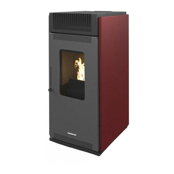
Page 8: Description Of The Stove
DESCRIPTION OF THE STOVE Height Width Depth Weight (net) Diameter of flue gas pipe Heating output reduced-nominal 3,5 – 10 Max heating volume Tank capacity 12,6 Consumption min-max kg/h 0,86 – 2,2 Flue gas temperature min-max °C 88 – 150 Efficiency at reduced-nominal P. -
Page 9: Installatio
INSTALLATION Installation not allowed Installation in premises with fire hazards is forbidden. Installation in residential premises (except for sealed operation appliances) • In which there are liquid fuel-operated appliances with continuous or intermittent operation, which draw the combustion air in the room in which they installed, •... - Page 10 In any case the temperature of the adjacent combustible materials must not reach a temperature equal to or greater than the room temperature increased by 65 The minimum volume of the premises in which to install the appliance must be greater than 15 m VENTILATION AND AERATION OF THE INSTALLATION PREMISES Ventilation is deemed sufficient when the room is equipped with air inlets according...
-
Page 11: Fumes Exhaust System
In the presence of type B gas appliances with intermittent operation not intended for heating, they must have their own aeration and/or ventilation opening. The air inlets must meet the following requirements. • They must be protected with grids, metal mesh, etc., but without reducing the net useful section;... -
Page 12: Smoke Duct
• Moisture resistance (resistance to condensation) • Class or level of corrosion and specification of the materials constituting the inner wall in contact with the fumes. • Soot fire resistance class; • Minimum distance from combustible materials • Where due to high efficiency a pellet stove has fumes at a temperature off less than 160 C + ambient (see technical data) The installer of the fumes exhaust system, once the installation is complete and the... - Page 13 Counter-slope sections are not allowed; • The smoke ducts must have along their entire length, a diameter that is no less than that of the attachment of the appliance exhaust pipe; any section changes are allowed only on the inlet to the chimney; •...
-
Page 14: Combustion Products Outlet Quota
• Operate under negative pressure (operation under positive pressure is not allowed) • Have a preferably circular internal section; square or rectangular sections must have rounded corners with a radius of no less than 20 mm (hydraulically equivalent sections may be used, as long as the ratio between the longer side and the shorter side of the rectangle, which circumscribes the section, is in any case no greater than 1.5);... -
Page 15: Fumes Exhaust System Product Requirements
or make the expulsion of the combustion products difficult or from openings or accessible areas. Reflux area The outlet quota must be outside the reflux area calculated according to indications below. Near the ridge one considers the lowest between the two. Buffer area for outlet quota Clear area for outlet quota above the roof slope (β>10... -
Page 16: Technical Installation Documentation
The fumes exhaust system interlocked with appliances supplied by solid fuels require soot fire resistance, and the specification must be indicated by the letter G followed by the distance from combustible materials in millimeters (XX) (in compliance with 1443:2006) In the event of pellet appliances, the fumes exhaust systems must be airtight; if double designation elements are used (G and o, with or without seal elastomer) for connecting the appliance to the chimney, one must comply with the minimum distance XX millimeters , indicated for designation G;... -
Page 17: Pellets And Feeding
PELLETS AND FEEDING Pellets are made by applying high pressure to sawdust, or wood waste products (not containing paint) from sawmills, carpentry and other activities related to processing and working with wood. Given that it does not use any glue to hold it together this type of fuel is completely environmentally friendly. -
Page 18: User Interface Keybord Remote Control
USER INTERFACE THE KEYBOARD REMORE CONTROL Through the console you can have a dialogue with the control board simply by pressing a few buttons. The display and LED indicators inform the operator of the operating status of the heater. In programming mode, various parameters are displayed, which can be modified by pressing the keys. -
Page 19: Operating Mode
What are the Leds? The meaning of led ON Set room programming SET ROOM SET POWER Set power programming Timer program ON TIMER PROGRAM Stove in alarm status ALARM AUGER ON Auger is moving Exchanger\pump on EXCHANGER-PUMB Working state ON\OFF OPERATING MODE Described below are the normal functions of the controller that is ordinarily installed in an air heater, with respect to functions available to users. - Page 20 3- Fire On: After the flue temperature has reached and surpassed the level stated the value, the system will enter the on mode and display “Flame Present” on the display, with the ON/ OFF LED flashing. In this phase. (with the feed screw LED on intermittently) and the glow plug (and its LED) will switch off.
- Page 21 7- Room temperature reaches the set temperature: When the ambient temperature has reached the level set, the power of the heater automatically reduces to the minimum level. At this point, the display will show the message “Modulate”. If the room temperature drops below the set temperature, the heater will return to working mode at the power previously 8- Stand-by: If enabled in the menu, the stand-by function allows you to turn off the heater once the following conditions are satisfied.
-
Page 22: Menu
MENU To access the menu, press and hold P1. The menu is subdivided into various levels and items that allow access to the settings and programming of the system. Lavel 1 Lavel 2 Lavel 3 Value M1 - set clock M-T-W-T-F-S-S 01 –... - Page 23 Lavel 1 Lavel 2 Lavel 3 Value 11 - Start prog 2 Off – 0 – 23:50 12 - Stop prog 2 Off – 0 – 23:50 On/Off 13 - Monday prog 2 On/Off 14 - Tuesday prog 2 15 - Wednesday prog 2 On/Off 16 –...
- Page 24 Lavel 1 Lavel 2 Lavel 3 Value 03- Deutsch M4 – Stand-by On/Off 01- Stand-by M5 – Buzzer 01- Buzzer Mode On/Off M6 – Initial Load 01- Initial Load 90” M7 –Stove state 01- Stove state 01 – Auger state info 02 –...
- Page 25 *Program day (M2-2): Select the menu “M2-2 program day” and press P3 to see and enable or disable the various parameters for programming the daily chrono settings. It is possible to set two functioning slots, the first with START1 Day and STOP1 Day and the second with START2 Day and STOP2 Day.
- Page 26 Program 2 Menu level Selection Meaning Possible values M2-3-11 START PROG 2 Wake time OFF -0-23:50 M2-3-12 STOP PROG 2 Off time OFF-0-23:50 M2-3-13 MONDAY PROG 2 ON/OFF M2-3-14 TUESDAY PROG 2 ON/OFF M2-3-15 WEDNESDAY PROG 2 ON/OFF M2-3-16 THURSDAY PROG 2 Reference day ON/OFF M2-3-17...
- Page 27 *Program weekend (M2-4): Allows you to enable/disable and set the chronothermostat functions on the weekend (day6 and day7, or Saturday and Sunday). To enable, press P3 on the “chrono weekend” item and select “on” by pressing P1 /to go down) or P2 (to go up).
- Page 28 Alarm Mode (M5): Allows you to enable or disable the buzzer on the controller when the alarm goes off. To enable or disable, press P1 or P2 respectively. To confirm, press P3. First Charge (M6): This function is only available when the heater is OFF. It allows the feed screw to load at the first start of the heater, when the pellet tank is empty.
-
Page 29: Electrical Layout
Electrical Layout MAINTENANCE Maintenance warnings Inspection and maintenance operations must be carried out by specialized technicians who are aware of the directions reported in this manual. Before currying out any work, make sure that: • The power cable’s plug has been pulled out, as the generator might have been programmed to turn on. - Page 30 Have the generator, vents and smoke pipe cleaned and checked by specialized personel every. DAILY CLEANING TO BE CARRIED OUT BY THE USER Daily cleaning must be carried out by the generator’s user with the utmost care after reading the instructions related to the procedures that need to be carried out later described in this manual.
-
Page 31: Routine Maintenance
If there is an ash collector tray, vacuum the ash deposits Please note: use a suitable vacuum cleaner with a special container to separate the collected ash. Cleaning the lower sump (if there is one ) Some stove models have an inspection sump behind the ash drawer or underneath the combustion chamber. -
Page 32: Alarms
ALWAYS FOLLOW THE INSTRUCTIONS IN MAXIMUM SAFETY CONDITIONS! • With the generator fully cooled down, switched off and disconnected from the mains electricity. • Failure to clean jeopardy dishes safety! • To ensure correct operation the generator must undergo routine maintenance by a qualified technician at least once a year. - Page 33 1- Black out: During the heater’s work mode, it might run out of energy. When it restarts, if the blackout period was less than stated in parameter’s value, the heater will re-enter the WORK mode; otherwise, the alarm will sound. The display will show the message “Al 1 alar al 1 Blackout”...
-
Page 34: Combustion Phase Of Flames Simulating
COMBUSTION PHASE OF FLAMES SIMULATING Combustion phase of flames simulating 1. PHASE 2. PHASE After pressing the ON button the device begins Approximately afet 4 – 4,5 minutes the first flame to take fuel and the heater is activated 3. PHASE 4. - Page 35 Warm houses, happy smiles Your happiness is treasure for us Barakfakih mahallesi 10 cadde No:2 Barakfakih organize sanayi bölgesi Kestel/BURSA/TÜRKİYE PHN: +90 224 384 11 10 FAX: +90 224 384 11 14 e-mail: hosseven@hosseven.com.tr www.hosseven.com.tr...
Need help?
Do you have a question about the P10 and is the answer not in the manual?
Questions and answers