Table of Contents
Advertisement
Quick Links
Advertisement
Table of Contents

Related Manuals for IBA PADU-8-M


Summary of Contents for IBA PADU-8-M
- Page 1 ibaPADU-8-M Parallel A/D Converter Unit for Fast Measurement Manual Issue 1.9...
- Page 2 Required corrections are contained in the following regulations or can be downloaded on the Internet. The current version is available for download on our web site http://www.iba-ag.com. Protection note Windows® is a label and registered trademark of the Microsoft Corporation. Other product and company names mentioned in this manual can be labels or registered trademarks of the corresponding owners.
-
Page 3: Table Of Contents
ibaPADU-8-M Manual Table of contents About this manual.....................5 Target group ...................... 5 Notations ......................5 Used symbols ....................6 Introduction .......................7 Scope of delivery ....................7 Safety instructions....................8 Designated use ....................8 Special advices ....................8 System requirements..................9 Hardware ......................9 Software ...................... - Page 4 Typical Configuration ..................19 10.1.2 Hardware Settings ..................20 10.1.3 Checking the Communication with the Help of ibaDiag ........22 10.1.4 Input Resources iba FOB-M/IN............... 24 10.1.5 Output Resources for ibaFOB-M (FOB-M/Out)..........25 10.1.6 Control of ibaPADU-8-M in ibaLogic application program....... 26 10.1.7 Data Buffer Size ....................
-
Page 5: About This Manual
ibaPADU-8-M Manual About this manual This manual describes the construction, the use and the operation of the device ibaPADU-8-M. Target group This manual addresses in particular the qualified professionals who are familiar with handling electrical and electronic modules as well as communication and measurement technology. -
Page 6: Used Symbols
Manual ibaPADU-8-M Used symbols If safety instructions or other notes are used in this manual, they mean: The non-observance of this safety information may result in an imminent risk of death or severe injury: By an electric shock! Due to the improper handling of software products which are coupled to input and output procedures with control function! The non-observance of this safety information may result in a potential risk of death or severe injury! -
Page 7: Introduction
128 binary channels with up to 25,000 samples / s. This operational mode is supported by PCI cards in combination with the iba Online Data Acquisition software ibaScope only! The master ibaFOB in that case controls the ADC converter triggering with an ac- curacy of max. -
Page 8: Safety Instructions
Manual ibaPADU-8-M Safety instructions Designated use The device is electrical equipment. It may be used only in the following applications: Automation of industrial systems Measurement data logging and analysis Applications of ibaSoftware products (ibaPDA, ibaLogic etc.) The device may not be operated in mains supply circuits! Special advices Important note Do not open the device! -
Page 9: System Requirements
Online measurement/monitoring software ibaScope V 3.0.01 or higher ibaLogic (SoftPLC) Version 3.60 or higher ibaPDA-V6 Version 6.15.0 or higher ibaChatter (available from iba America, LLC, www.iba-ag.com) Analysis software ibaAnalyzer Version 3.0 and higher Issue 1.9... -
Page 10: Mounting And Dismounting
Manual ibaPADU-8-M Mounting and dismounting Mounting 1. Locate the DIN rail mounting clip on the rear side of the device. Place the device on the DIN rail so that the top part the mounting clip engages the top part of the rail appropriately. -
Page 11: Device Description
ibaPADU-8-M Manual Device description Properties 24 V DC unregulated external power supply required (18…32 V input voltage pos- sible) DIN rail mountable, EMI protected, robust metal housing 3 LED device status indicators (Run, Link, Error) TX/RX fiber-optic ports for transmission of measured data and reception of configu- ration requests as well as multiplexing of up to 96 devices ... -
Page 12: Device View, Interfaces And Operating Elements
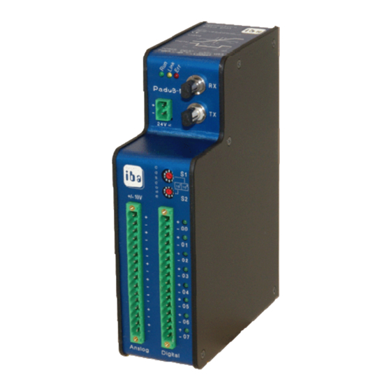
Manual ibaPADU-8-M Device view, interfaces and operating elements Front View Description Top View Serial number and support informa- Status LEDs L1…L3 tion RX port (X11) 24 V DC Power Connector (X14) TX port (X10) Address Switches S1 & S2 Binary input status LED (L4-L11) Binary inputs connector (X5) Bottom View Service interface... -
Page 13: Terminal Blocks Pin Connections X14, X1, X5
ibaPADU-8-M Manual 7.2.4 Terminal Blocks Pin Connections X14, X1, X5 Note: the counting order is from the top to the bottom. Power Supply Connections X14 Connection +24 V Analog X1 and Binary Pin Connections X5 Analog Digital Connection Connection + channel 0 BE00 + - channel 0 BE00 -... -
Page 14: Binary Led Indicators L4
Firmware may only be updated by iba! A 9-pin SUB-D port, found on the underside of the device, may be used to load new firmware for the device. New firmware is loaded via a V.24 interface. Please contact iba regarding loading new firmware. -
Page 15: System Integration
Manual System integration As far as no special relation to a PC board is necessary the ibaFOB-4i / -4o and/or iba- FOB-io are referred to as ibaFOB card. It is assumed that the card(s) run in iba FOB-M mode (controlled by software application) ibaPADU-8-M devices are interconnected in a ring structure with the ibaFOB serving as a central controller for all connected devices. -
Page 16: Process Monitoring Topology Example
For continuous process monitoring, multiplex operation of the device network is not required. If an ibaPADU-8-M is connected with a fiber optic link of an iba- FOB card, no other ibaPADU type can be connected to the same link. -
Page 17: Online Machine Condition Monitoring Topology
The use of the ibaBM-FOX-i-3o splitter in conjunction with ibaPADU-8-M is not sup- ported. Due to the bidirectional data transfer between ibaPADU-8-M and ibaFOB-card it is not possible to split the signals. If a multiplication of signals is required, please contact iba. Issue 1.9... -
Page 18: Settings Of The Device
51000 Hz would be dampened 6dB by the static low-pass filter. This signal would be noticeable for signal strengths above 20 dB. If a device for low-frequency applications should be required, iba can supply a variant of this device for sampling at 1 kHz or less, with a static low-pass filter. Please contact iba for further details. -
Page 19: Data Selection For Ibapadu-8-M
ibaPADU-8-M Manual Data Selection for ibaPADU-8-M ibaPADU-8-M is actually supported by ibaLogic-V3, ibaScope and ibaPDA-V6 software. The following chapters describe example configurations in ibaLogic and ibaPDA. The settings in ibaScope correspond to the settings in ibaLogic, although the dialogs are slightly different. -
Page 20: Hardware Settings
In ibaLogic there are corresponding dialogs. Basically, there are two operational modes: FOB-F and FOB-M. FOB-F is the mode of operation for usual data acquisition with the major part of iba de- vices such as ibaPADU-8, -16, -32, ibaLink-SM-64-io, ibaLink-SM-128V-i-2o, ibaNet750-BM etc. - Page 21 ibaPADU-8-M Manual Then click on button <Configuration FOB I/O> to open the setup dialog for the ibaFOB- card. Select the corresponding ibaFOB-card in the tree on the left side. On the right side you see the settings of the selected card. Choose the line of the link which is connected to the ibaPADU-8-M and select FOB-M Mode in the fields for both “Receiver Format”...
-
Page 22: Checking The Communication With The Help Of Ibadiag
Manual ibaPADU-8-M 10.1.3 Checking the Communication with the Help of ibaDiag Start the diagnostics program over menu “Hardware - ibaDiag”. Select the ibaFOB-card which is connected to the ibaPADU-8-M in the tree on the left side. On the right side you see a simplified representation of the card with the 7-segment- display for the card address of this type and the LEDs showing the status of every link. - Page 23 ibaPADU-8-M Manual The graphical representation of the ibaPADU-8-M device is not animated. The large table on the left side and the fields on the right side of the Padu picture show the settings of the PADU setup. If the ibaFOB card is set to active mode by means of ibaDiag, which is only possible when ibaLogic is not running at this time, you may call the PADU setup dialog window by clicking on the button <Setup Padu M>.
-
Page 24: Input Resources Iba Fob-M/In
Status of data buffer (true, if number of values > buffer size) Quantity of available data (multiples of 10), if data available. Link status (true, if iba FOB M active and link available) True, if link status ok and ibaPADU-8-M activated. -
Page 25: Output Resources For Ibafob-M (Fob-M/Out)
ibaPADU-8-M Manual 10.1.5 Output Resources for ibaFOB-M (FOB-M/Out) The board ibaFOB-io-S provides one bidirectional fiber optical link, the ibaFOB-4i-S to- gether with ibaFOB-4o four links, respectively. Up to four ibaFOB-4i-S / 4o boards are supported by ibaLogic (= max. 16 optical links with up to 96 ibaPADU-8-M devices each). -
Page 26: Control Of Ibapadu-8-M In Ibalogic Application Program
When using the device with ibaLogic the required parameters must be evaluated in the application and transferred to the device over the FOB-M output resources. For the supply of the parameters iba developed a sample function block FOBM_Control which is available from iba on request. -
Page 27: Data Buffer Size
Data Buffer Size In order to grant the proper operation with continuous data streams, there are several buffers of fixed size. (This is not important in case of single measurements) iba-M buffer size: 1.024 values per measuring channel. Driver buffer size: 25.000 values per measuring channel. -
Page 28: Configuring With Ibapda
10.2.1 Configuring ibaPADU-8-M 1. If several iba PCI cards are used in ibaPDA, set the board connected to ibaPADU-8-M to the interrupt mode "Master internal" and set the option "In use". 2. Create the device module by one of the following actions: ... - Page 29 ibaPADU-8-M Manual Right-click the link of the FOB-D or FOB-S card to which the ibaPADU-8-M is con- nected and select “Add module” - "Padu 8-M" from the submenu or click to the blue text link "Click to add module…" and select the Padu 8-M inter- face from the displayed list.
- Page 30 Note that the difference between FOB-M link time base and general ibaPDA acquisition time base must not be too high to avoid exceeding the buffer limits. iba AG recommends a multiple between 25 and 100. Device address: address 0..95, according to the rotary switch settings S1 and S2 4.
- Page 31 ibaPADU-8-M Manual You can change the parameters manually. It is possible to define signal comments by clicking the button at the end of the name field. You can also display other signal properties in the grid with a right mouse click on the headline of the grid.
-
Page 32: Configuring Triggers
Manual ibaPADU-8-M 10.2.2 Configuring Triggers Alternative to the definition of single trigger events, ibaPDA supports the definition of multiple trigger events as a trigger pool. For using the trigger pool you must first define all possible trigger events. In the 2 step you must select the predefined events from the trigger pool to start and to stop storing the data. - Page 33 ibaPADU-8-M Manual The custom tab contains the regular expression builder. Finish the definition of one trigger event with <OK> Define further trigger events in the same way. Issue 1.9...
- Page 34 Manual ibaPADU-8-M Result: In the signal grid of the trigger module you see the overview of all defined trigger events. 2. Use the trigger events in the data store configuration The signals from the trigger modules can be used as triggers in the datastore. Each datastore has a start trigger pool and a stop trigger pool.
-
Page 35: Configuring The Data Store
ibaPADU-8-M Manual 10.2.3 Configuring the Data Store After finishing the configuration of the ibaPADU-8-M device, it is necessary to setup the data storage. For this, select "Configure – Data storage" in the main menu. Proceed as follows: 1. Activate and name the data store 2. -
Page 36: Configuring The Signal View
Manual ibaPADU-8-M 10.2.4 Configuring the Signal View After closing the I/O Manager and the Data storage configuration you are in the ibaPDA client main view. Mainly ibaPDA has three view types: The trend graph , the Scope view and the FFT view ... -
Page 37: Technical Data
Manual Technical data Order number iba 10.120300 Mechanical stability and DIN IEC 68-2-6; test parameters (all 3 axes) 2 g rms 90 Min @ 0..250 Hz / axis (all ibaPADU-8 types); EMI test parameters EN 55011 (Class A); EN61000-4-6 (Class 3); EN61000-4-3/ENV 50204 (Class 3) °... -
Page 38: Dimensional Drawing
Manual ibaPADU-8-M 11.1 Dimensional Drawing Dimensions given in mm Issue 1.9... -
Page 39: Support And Contact
Koenigswarterstr. 44 90762 Fuerth Germany Phone: +49 911 97282-0 Fax: +49 911 97282-33 Email: iba@iba-ag.com Contact: Mr. Harald Opel Regional and Worldwide For contact data of your regional iba office or representative please refer to our web site www.iba-ag.com. Issue 1.9...
Need help?
Do you have a question about the PADU-8-M and is the answer not in the manual?
Questions and answers