Advertisement
Advertisement

Subscribe to Our Youtube Channel
Related Manuals for Olympus CLH-SC


Summary of Contents for Olympus CLH-SC
- Page 1 MAINTENANCE MANUAL CLH-SC...
- Page 2 INTRODUCTION Repairs of this product require high-grade special knowledge and technique. We recommend to contact the Olympus agent in your country when product Goes out of order. For remodeling or repairs to be done by the agent or person not authorized...
-
Page 3: Table Of Contents
CONTENTS 1. SPECIFICATION OF PRODUCTS 2. DESCRIPTION OF BLOCK 3. CIRCUIT DIAGRAM 1 2 0 V 2 2 0 V 2 3 0 V 2 4 0 V 4. TROUBLESHOOTING 5. DISASSEMBLING PROCEDURE 6. EXPLODED PARTS DIAGRAM 7. PARTS LIST... -
Page 4: Specification Of Products
1. SPECIFICATION OF PRODUCTS 1. Features The CLH-SC is a simple high intensity light source designed for use with a medical rigid scope or an endoscope with an eyepiece of the same shape as of a medical rigidscope. 2. Specifications... - Page 5 PRODUCT SPECIFICATIONS Item Specifications For destinations Applied laws and regulations, classifications, etc. EU/EFTA Class: I CE marking FDC law UL mark/CUL mark Panel and outer casing Clean with the gauze moistened with 70% ethyl alcohol, 70% isopropyl alcohol or neutral cleanser. Dry sufficiently after cleaning with alcohol.
- Page 6 Among the devices designed to apply medical treatment with electronics to a patient, those which are not confirmed in safety when combined with the CLH-SC. b. Among the devices not designed to apply medical treatment with electronics to a patient, those which are not confirmed in safety such as a leakage current, etc.
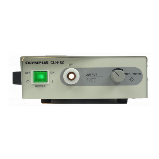
- Page 7 PRODUCT SPECIFICATIONS 4. Nomenclature 4-1. Front panel 1. Power switch 2. Output connector 3. Brightness control 1. Power switch Push the right side to turn on the unit. The switch lamp lights and the illumination lamp (halogen) lights up. 2. Output connector Supplies an illumination light to the scope and light guide cable connected.
- Page 8 PRODUCT SPECIFICATIONS System Diagram OES video system (OTV-SC) High intensity light source unit (CLH-SC) Video monitor Endoscope for endoscope Video adapter OEV series Rigid scope Video adapter Light guide...
-
Page 9: Description Of Block
2. DESCRIPTION OF BLOCK 1. Operation of Block Operation of the CLH-SC is described using a block diagram (2-2). Power supplied on the power cable is applied to the interlock switch through two fuses. The power passing through the interlock switch is applied to the power switch on the front panel and is then sent to the terminal block. - Page 10 UNIT NAME MODEL BLOCK DIAGRAM CLH-SC...
- Page 11 UNIT NAME MODEL 120V CLH-SC DATE PAGE 99-01...
- Page 12 UNIT NAME MODEL 220V CLH-SC DATE PAGE 99-01...
- Page 13 MODEL UNIT NAME 230V CLH-SC DATE PAGE 99-01...
- Page 14 UNIT NAME MODEL 240V CLH-SC DATE PAGE 99-01...
-
Page 15: Troubleshooting
TROUBLESHOOTING TROUBLESHOOTING Symptoms 1. Power is not supplied. 2. The lamp does not light at all, burns out soon or turns off after once turning on. 3. The fan does not work. 4. Brightness is insufficient. 5. Light can not be controlled. - Page 16 TROUBLESHOOTING [Symptom: Power is not supplied.] Start The supply voltage is abnormal, Is power provided at or the power cord is defective. the inlet? Is power provided in the The interlock switch is input side of the power defective. switch? Is power provided in the The power switch is defective.
- Page 17 TROUBLESHOOTING [Symptom: The lamp does not light at all, burns out soon or turns off after once turning on.] Start Replace the lamp, and Is the lamp burnt? age it for a while. Is the lamp burnt soon? Measure the voltage applied to the lamp (with the lamp connected).
- Page 18 TROUBLESHOOTING [Symptom: The fan does not work.] Start Only one fan works. Change connection of Do the both two fans the connectors. work? Do the fans work? Check wiring and connection The fan is defective of the connectors. (one fan). Check the voltage applied to the fan.
- Page 19 TROUBLESHOOTING [Symptom: Brightness is insufficient.] Start Check the lamp for deterioration (darkness). Replace the lamp. Is the lamp normal? Is the lamp correctly Mount the lamp correctly. mounted? Measure the voltage applied to the lamp (with the lamp connected). 100 V class 15 V±0.75 V Check the supply voltage.
- Page 20 TROUBLESHOOTING [Symptom: Light can not be controlled.] Start Check to see if the control knob on the front panel makes idle rotation? Tighten the ACU screw Does the control to fix the control. rotate idly? Check to see if the shaft Does the shaft rotate? is caught by the stopper screw?
-
Page 21: Disassembling Procedure
DISASSEMBLING/ASSEMBLING PROCEDURE 5. DISASSEMBLING/ASSEMBLING PROCEDURE 1. Precautions on Disassembling/Assembling Replace the parts and wires to the original positions. For electrical safety and standard, be sure to reassemble the following parts to the original states. Insulation tube and mylar sheet Cables clamped and separated from the heating parts or high-voltage parts Cover screws with a toothed lock washer to suppress a radiation noise Use the specified parts. - Page 22 DISASSEMBLING/ASSEMBLING PROCEDURE 4. Disassembling 1. Top cover (1) Remove the door by turning the knob. (2) Remove the eight screws which secure the top cover to the main body. Phillips screwdriver No. 2 (3) Remove the top cover from the main body.
- Page 23 DISASSEMBLING/ASSEMBLING PROCEDURE Upper heat shielding plate (1) Remove the three screws which secure the upper heat shielding plate to the main body. Phillips screwdriver No. 2 (2) Remove the upper heat shielding plate from the main body. UPCH10U (1) Remove the terminal of Socket harness from the UPCH10U board.
- Page 24 DISASSEMBLING/ASSEMBLING PROCEDURE (4) Remove the two screws which secure the UPCH10U to the chassis. Phillips screwdriver No. 2 (5) Remove the UPCH10U from the chassis. (1) Remove the two screws which secure the fan to the chassis. Phillips screwdriver No. 2 (2) Remove the fan from the chassis.
- Page 25 DISASSEMBLING/ASSEMBLING PROCEDURE Transformer (1) Remove the four screws which secure the transformer to the chassis. Phillips screwdriver No. 2 (2) Remove the transformer from the chassis. Frame (1) Remove the three screws which secure the frame to the chassis. Phillips screwdriver No. 2 (2) Remove the frame from the chassis.
-
Page 26: Exploded Parts Diagram
EXPLODED PARTS DIAGRAM EXPLODED PARTS DIAGRAM COVER & SHASSY FIG. 1/3 CLH-SC... - Page 27 EXPLODED PARTS DIAGRAM MAIN UNIT FIG.2/3 CLH-SC...
- Page 28 EXPLODED PARTS DIAGRAM FIG.3/3 CABLE CLH-SC...
-
Page 29: Parts List
PARTS LIST 7. PARTS LIST PARTS No. INDEX PARTS NAME SPECIFICATION REMARK DB068500 1-A1 FUSE DH205100 2-A3 TERMINAL DH305600 1-A3 FUSE POWER CONNECTOR DK521600 1-A3 DY243000 1-D4 POWER SW POWER SW 100V CLASS DY243100 1-D4 POWER SW POWER SW 200V CLASS DY249300 2-A2 INTER LOCK SW... - Page 30 PARTS LIST SPECIFICATION REMARK PARTS No. INDEX PARTS NAME CCUK3x6SZ 1-C2 SCREW WE1 39002 CCUK4x6SZ 2-C2 SCREW WE1 39005 AB6x8SB SCREW WE402456 1-A1 SCREW WE1 06060 CSK3x6SA 1-A2 WE168012 CUKSK3x10SZ 1-B4 SCREW HCBK3x6SA SCREW WE1 29002 1-A3 WE306009 HWB4SA 2-A3 WASHER...
- Page 31 OLYMPUS OPTICAL CO., LTD. San-Ei Building, 22-2, Nishi Shinjuku 1-chome, Shinjuku-ku, Tokyo, Japan OLYMPUS OPTICAL CO., (EUROPA) GMBH (Premises/ Goods delivery) Wendenstrasse 14-16, D-20097 Hamburg, Germany (Letters: Postfach 104908, D-20034 Hamburg, Germany) OLYMPUS AMERICA INC. Two corporate Center Drive Melville, N. Y.
Need help?
Do you have a question about the CLH-SC and is the answer not in the manual?
Questions and answers