Table of Contents
Advertisement
Available languages
Available languages
Quick Links
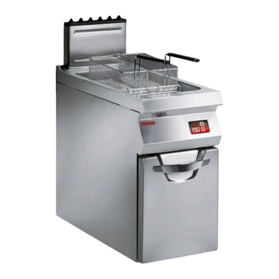
FRIGGITRICE GAS
GAS FRYER
GAS-FRITEUSE
FRITEUSE À GAZ
FREIDORA GAS
MANUALE D'USO E INSTALLAZIONE
USE AND INSTALLATION MANUAL
BEDIEN- UND INSTALLATIONSHANDBUCH
MANUEL D'UTILISATION ET D'INSTALLATION
MANUAL DE USO E INSTALACIÓN
091FR1ID
191FR2ID
Italiano
English
Deutsch
Français
Español
Ed.1
12/2013
3222420
IT
GB
DE
FR
ES
Advertisement
Chapters
Table of Contents

Related Manuals for Angelo Po 091FR1ID


Summary of Contents for Angelo Po 091FR1ID
- Page 1 FRIGGITRICE GAS GAS FRYER 091FR1ID GAS-FRITEUSE 191FR2ID FRITEUSE À GAZ FREIDORA GAS MANUALE D’USO E INSTALLAZIONE USE AND INSTALLATION MANUAL BEDIEN- UND INSTALLATIONSHANDBUCH MANUEL D’UTILISATION ET D’INSTALLATION MANUAL DE USO E INSTALACIÓN Italiano English Deutsch Français Español Ed.1 12/2013 3222420...
-
Page 3: Table Of Contents
INDICE rif. capitoli pag. 1 INFORMAZIONI GENERALI ..........3 2 INFORMAZIONI TECNICHE ..........5 3 SICUREZZA ............... 7 PARTE 4 USO E FUNZIONAMENTO ..........9 5 MANUTENZIONI .............. 15 6 GUASTI ................17 7 MOVIMENTAZIONE E INSTALLAZIONE ......20 8 REGOLAZIONI ..............26 PARTE 9 SOSTITUZIONE PARTI ........... - Page 4 Regolazioni, raccomandazioni segnali di, 6 Trasporto, 20 per le, 26 Sicurezza, dispositivi di, 6 Ugello bruciatore, sostituzione, 28 Ricerca guasti, 17 Sollevamento e movimentazione, 21 Uso e funzionamento, Ripristino apparecchiatura, 14 Sostituzione parti, raccomandazioni raccomandazioni, 9 per la, 27 Scarico fumi, allacciamento, 24 Uso, consigli per, 14 Sostituzione gruppo accensione, 28 Scopo del manuale, 3...
-
Page 5: Informazioni Generali
INFORMAZIONI GENERALI RACCOMANDAZIONI PER IL LETTORE Per rintracciare facilmente gli argomenti specifici di parte: contiene tutte le informazioni ne- interesse, consultare l’indice analitico posto all’ini- cessarie ai destinatari omogenei, cioè tutti gli zio del manuale. operatori esperti e autorizzati a movimentare, Questo manuale è... - Page 6 IDENTIFICAZIONE COSTRUTTORE E APPARECCHIATURA La targhetta di identificazione raffigurata, è applica- ) Consumo gas ta direttamente sull'apparecchiatura. In essa sono ) Indicatore gas collaudo riportati i riferimenti e tutte le indicazioni indispensa- ) Tensione (V) bili alla sicurezza di esercizio. ) Frequenza (Hz) Targa complementare ) Potenza elettrica assorbita (W)
-
Page 7: Informazioni Tecniche
è stata progettata e costruita per la frittura dei ci- tura è prodotta in più versioni (vedi figura). bi, nell'ambito della ristorazione professionale. 091FR1ID (22 lt) 191FR1ID (22 lt + 22 lt) Organi principali A)Vasca di frittura: realizzata in acciaio inox. - Page 8 Vedi tabelle e "Scheda allacciamenti" in fondo al manuale. DISPOSITIVI DI SICUREZZA Anche se l'apparecchiatura è completa di tutti i di- 091FR1ID spositivi di sicurezza, in fase di installazione e allac- ciamento essi dovranno, se necessario, essere integrati con altri in modo da rispettare le leggi vi- genti in materia.
-
Page 9: Sicurezza
DOTAZIONE ACCESSORI Alla consegna viene fornita la seguente dotazione: A)Coperchio vasca B)Prolunga scarico olio C)Cestelli IDM-39619400400.tif ACCESSORI A RICHIESTA A richiesta l'apparecchiatura può essere corredata dei seguenti accessori. A)Filtro olio (FO) B)Raccoglitore olio (RO) C)Camino alto tipo A D)Camino alto tipo A con dispositivo di rompitiraggio antivento E)Piedi di appoggio F) Kit per installazione "a ponte"... - Page 10 loro funzioni principali, in particolare quelle relati- – Indossare sempre i dispositivi di protezione indi- ve all'accensione ed allo spegnimento. viduali (guanti, mascherine, occhiali, ecc.), come – Utilizzare l'apparecchiatura solo per gli usi previ- previsto dalle leggi vigenti in materia di sicurezza sti dal fabbricante.
-
Page 11: Uso E Funzionamento
USO E FUNZIONAMENTO RACCOMANDAZIONI PER L'USO E FUNZIONAMENTO Importante L'incidenza degli infortuni derivanti dall'uso di tuare solo gli usi previsti dal costruttore e non apparecchiature dipende da molti fattori che manomettere nessun dispositivo per ottenere non sempre si riescono a prevenire e controlla- prestazioni diverse da quelle previste. - Page 12 IMPOSTAZIONE ORA CORRENTE Procedere nel modo indicato. 4 - Premere il tasto (D) per memorizzare il nuovo 1 - Premere il tasto (B) per arrestare il ciclo di cot- valore. tura e disattivare l'apparecchiatura. Sul display (A) il valore dei minuti inizia a lam- La spia luminosa (P) si accende.
- Page 13 IMPOSTAZIONE TEMPO DI COTTURA Cottura manuale 3 - Premere nuovamente il tasto (D) per avviare il Procedere nel modo indicato. ciclo di cottura. 1 - Premere il tasto (D). Se, a ciclo di cottura avviato, si preme il tasto Sul display (A) compare l'ultimo valore impo- (D) sul display viene visualizzato per 4 secondi stato.
- Page 14 ACCENSIONE E SPEGNIMENTO APPARECCHIATURA Accensione Spegnimento 1 - Agire sull'interruttore sezionatore dell'apparec- 1 - Mantenere premuto il tasto (B) per circa 6 se- chiatura per attivare l'allacciamento alla linea condi per arrestare il ciclo di cottura e spegnere elettrica principale. l'apparecchiatura.
- Page 15 4 - Premere il tasto (C) per attivare la modalità di 8 - Per visualizzare la temperatura impostata, du- inserimento temperatura. rante la fase di cottura, premere il tasto (C). 5 - Agire sui tasti (F-G) per impostare la tempera- Arresto tura di cottura.
- Page 16 RIPRISTINO APPARECCHIATURA In caso di intervento del termostato di sicurezza è necessario ripristinare le condizioni iniziali di funzio- namento dell'apparecchiatura nel modo indicato. 1 - Lasciare raffreddare l'olio di 30-40°C. 2 - Aprire il portello (A). 3 - Premere il pulsante (B) del termostato di sicurezza intervenuto per riattivare l'alimentazione del gas.
-
Page 17: Manutenzioni
– Il massimo carico consigliato. per vasca, è di 2 – Usare periodicamente un polarimetro per misu- rare la percentuale di composti polari (valore max consentito 25 g/100 g in conformità alla CIRCO- LARE MINISTERO DELLA SANITÀ n. 1 deII'11 gennaio 1991). - Page 18 PULIZIA VASCA, CESTELLI E ACCESSORI Per questa operazione procedere nel modo indica- 1 - Spegnere e lasciare raffreddare l'apparecchia- tura (vedi pag. 12). 2 - Agire sull'interruttore sezionatore per disattiva- re l'alimentazione elettrica. 3 - Scaricare e filtrare l'olio (vedi pag. 13). 4 - Asportare e pulire i cestelli e la struttura reggi- cestelli (A).
-
Page 19: Guasti
8 - Verificare il corretto posi- zionamento del dispositi- vo di “ lenta accensione”. 9 - Spegnere l'apparecchiatu- ra, chiudere il rubinetto ali- mentazione 0° scollegare il manometro (C) e riavvitare la vite (B). 10-Richiudere il portello (A) ad operazione ultimata. 270°... - Page 20 TABELLA SEGNALAZIONE ALLARMI Allarme Cause Rimedi Le funzioni dell'apparecchiatura sono disabilitate e quindi non è possibile Avaria sonda termostato di eseguire cicli di cottura Ripristinare il termostato di sicurezza sicurezza (vedi pag. 14), se il problema persiste contattare il servizio assistenza. Le funzioni dell'apparecchiatura sono disabilitate e quindi non è...
- Page 21 Allarme Cause Rimedi Le funzioni dell'apparecchiatura sono disabilitate e quindi non è possibile eseguire cicli di cottura Intervento della diagnostica della scheda elettronica (vasca dx) Importante Contattare il servizio assistenza. Le funzioni dell'apparecchiatura sono disabilitate e quindi non è possibile eseguire cicli di cottura Intervento della diagnostica della scheda elettronica Importante...
-
Page 22: Movimentazione E Installazione
MOVIMENTAZIONE E INSTALLAZIONE RACCOMANDAZIONI PER LA MOVIMENTAZIONE E INSTALLAZIONE Importante Eseguire la movimentazione e l'installazio- Chi è autorizzato ad eseguire queste opera- ne nel rispetto delle informazioni fornite dal zioni dovrà, se necessario, organizzare un costruttore e riportate direttamente sull'im- "piano di sicurezza"... - Page 23 MOVIMENTAZIONE E SOLLEVAMENTO L'apparecchiatura può essere movimentata con un dispositivo di sollevamento a forche o a gancio di portata adeguata. Prima di effettuare questa opera- zione, controllare la posizione del baricentro del ca- rico. Importante Nell'inserire il dispositivo di sollevamento, fare attenzione al tubo di alimentazione gas.
- Page 24 VENTILAZIONE LOCALE Nel locale dove è installata l'apparecchiatura, devo- no essere presenti delle prese d'aria per garantire il corretto funzionamento dell'apparecchiatura e per il ricambio d'aria del locale stesso. Le prese d'aria devono avere dimensioni adeguate, devono essere protette da griglie e collocate in modo da non poter essere ostruite.
- Page 25 Per le apparecchiature in batteria sono disponibili, H)Kit trave di sostegno a richiesta, diversi kit di allestimento: F) Kit per installazione "a ponte" G)Kit telaio di appoggio IDM-39614401800.tif ALLACCIAMENTO GAS Importante Chi è autorizzato ad effettuare tale operazio- ne deve possedere capacità ed esperienza acquisita e riconosciuta nel settore specifico, dovrà...
- Page 26 ALLACCIAMENTO SCARICO FUMI 1 - Posizionare l'apparecchiatura sotto la cappa Importante (A) (vedi figura). Effettuare l'allacciamento nel rispetto delle Importante leggi vigenti in materia utilizzando il mate- riale appropriato e prescritto. L'accensione del ventilatore dell'impianto di aspirazione forzata deve comportare Allacciamento sotto cappa ad aspirazione for- l'apertura automatica del rubinetto di ali- zata...
- Page 27 6 - Serrare il pressacavo (F). 8 - Rimontare la protezione (C). 7 - Rimontare il coperchio (E). IDM-39619401900.tif TRASFORMAZIONE ALIMENTAZIONE L'apparecchiatura è stata collaudata dal costruttore con il proprio gas di rete, segnalato dall'adesivo ap- plicato sulla targhetta di identificazione. Se il tipo di gas da allacciare è...
-
Page 28: Regolazioni
COLLAUDO APPARECCHIATURA 3 - Verificare la regolare accensione e combustio- Importante ne del bruciatore. 4 - Verificare e, se necessario, regolare la pres- Prima della messa in servizio, occorre ese- guire il collaudo dell'impianto, per valutare sione e la portata del gas al massimo (vedi le condizioni operative di ogni singolo com- pag. -
Page 29: Sostituzione Parti
8 - Spegnere l'apparecchiatura, chiudere il rubi- 9 - Riavvitare le viti (D-E). netto alimentazione gas e scollegare il mano- 10-Richiudere il portello (A) ad operazione ultima- metro (F). IDM-39619402100.tif REGOLAZIONE ARIA PRIMARIA BRUCIATORE Per questa operazione procedere nel modo indica- 1 - Chiudere il rubinetto alimentazione gas. - Page 30 Qualora sia necessario sostituire dei componenti non originali e interventi straordinari che possono usurati, utilizzare esclusivamente dei ricambi origi- modificare i requisiti di sicurezza, senza l'autorizza- nali. Si declina ogni responsabilità per danni a per- zione del costruttore. Per la richiesta di componenti sone o componenti derivanti dall'impiego di ricambi seguire le indicazioni riportate nel catalogo ricambi.
- Page 31 DISMISSIONE E DEMOLIZIONE APPARECCHIATURA In fase di dismissione, è necessario effettuare una In fase di demolizione, selezionare tutti i compo- serie di interventi per fare in modo che l'apparec- nenti in funzione delle loro caratteristiche chimiche chiatura ed i suoi componenti non costituiscano un e provvedere allo smaltimento differenziato nel ri- intralcio e non siano facilmente accessibili.
- Page 33 CONTENTS ref. chapters page 1 GENERAL INFORMATION ..........3 2 TECHNICAL INFORMATION ..........5 3 SAFETY ................7 PART 4 USE AND OPERATION ............. 9 5 SERVICING ..............15 6 FAULT ................17 7 HANDLING AND INSTALLATION ........20 8 ADJUSTMENTS ............... 26 PART 9 REPLACING PARTS ............
- Page 34 Servicing, recommendations for, 15 Table of alarm indications, 18 Unpacking and packaging, 20 Setting the cooking time, 11 Technical data, 6 Use, useful advice for, 14 Standard accessories, 7 Testing of the appliance, 26 Useful advice for use, 14 Starting and stopping the cooking Transport, 20 cycle, 12 Well, baskets and basket support...
-
Page 35: General Information
GENERAL INFORMATION INFORMATION FOR THE READER To find the specific topics of interest to you quickly, 2nd part: contains all the information neces- refer to the index at the start of the manual. sary for special categories of reader, i.e. all This manual is subdivided into two parts. - Page 36 IDENTIFICATION OF CONSTRUCTOR AND APPLIANCE The nameplate shown here is fitted directly to the ) Gas consumption ) Testing gas indicator frame appliance. It contains references and all essential ) Voltage (V) information for operating safety. ) Frequency (Hz) Extra nameplate ) Electricity power consumption (W) ) Country of use ) Test voltage indicator...
-
Page 37: Technical Information
The fryer, referred to from now on as the appliance, meet varying user requirements (see diagram). is designed and produced for frying foods in the professional catering sector. 091FR1ID (22 lt) 191FR1ID (22 lt + 22 lt) Main Parts A)Frying well: in stainless steel. - Page 38 See tables and "Connection chart" at the back of the manual. SAFETY DEVICES Although the appliance is complete with all safety 091FR1ID devices, during installation and connection addi- tional devices must be added if necessary to com- ply with the relevant legal requirements.
-
Page 39: Safety
STANDARD ACCESSORIES The appliance is delivered complete with the follow- ing: A)Well lid B)Oil drain extension C)Baskets IDM-39619400400.tif OPTIONAL ACCESSORIES The appliance can be equipped with the following accessories on request. A)Oil filter (FO) B)Oil drain container (RO) C)Type A D)Type A tall fume exhaust vent with draught damper device. - Page 40 – All servicing operations requiring specific techni- – At the end of each session of use, make sure that cal knowledge or skills must only be carried out the burners are off, with the control knobs turned by qualified staff with recognised experience in off and the gas supply lines disconnected.
-
Page 41: Use And Operation
USE AND OPERATION RECOMMENDATIONS FOR USE Important The rate of accidents deriving from the use and the main functions. Use only as intend- of appliances depends on many factors ed by the constructor and never tamper which cannot always be foreseen and con- with any device to obtain performance lev- trolled. - Page 42 CURRENT TIME SETTING Proceed as follows. 4 - Press the key (D) to save the new value dis- 1 - Press the key (B) to stop the cooking cycle and played. deactivate the appliance. The value of the minutes on the display (A) will The light (P) comes on.
- Page 43 SETTING THE COOKING TIME Manual cooking 3 - Press the key (D) again to start the cooking cy- Proceed as follows. cle. 1 - Press the key (D) the last value set appears on If the (D) key is pressed after the cooking cycle the display (A).
- Page 44 SWITCHING THE APPLIANCE ON AND OFF Lighting Turning off 1 - Operate the appliance's master switch to con- 1 - Keep the key (B) pressed for about 6 seconds nect it to the electrical mains. to stop the cooking cycle and switch the appli- The mains light (P) comes on.
- Page 45 4 - Press key (C) to activate the temperature input 8 - To display the temperature set during cooking, mode. press key (C). 5 - Press keys (F-G) to set the cooking temperature. Stopping the data set on the control panel are retained in 1 - Press key (B) to stop the cooking cycle.
- Page 46 RESETTING THE APPLIANCE If the safety thermostat is tripped, the appliance has to be restored to the initial working conditions as fol- lows. 1 - Allow the oil to cool to 30-40°C. 2 - Open the hatch (A). 3 - Press the button (B) of the safety thermostat tripped to restore the gas supply.
-
Page 47: Servicing
well. SERVICING RECOMMENDATIONS FOR SERVICING Keep the appliance at peak efficiency by carrying Every 100 working hours have skilled, authorised personnel carry out the following operations. out the scheduled servicing procedures recom- – A check on the gas pressure and system tight- mended by the constructor. - Page 48 CLEANING THE WELL, BASKET SUPPORT AND ACCESSORIES To carry out this operation, proceed as follows. 1 - Switch the appliance off and leave it to cool (see page 12). 2 - Turn off the circuit-breaker to disconnect it from the electrical mains. 3 - Drain and filter the oil (see page 13).
-
Page 49: Fault
8 - Check that the "slow start-up" device is cor- rectly positioned. 9 - Switch off the appliance, turn off the gas supply tap , and disconnect the pres- 0° sure gauge (C) and retight- en the screw (B). 10-Close the door (A) when the operation is complete. - Page 50 TABLE OF ALARM INDICATIONS Alarm Cause Remedy The appliance’s functions are disa- bled so no cooking cycles can be car- ried out. Safety thermostat failure Reset the safety thermostat (see page 14); if the problem persists, call the af- ter-sales service. The appliance’s functions are disabled so no cooking cycles can be carried Start the cooking well probe...
- Page 51 Alarm Cause Remedy The appliance’s functions are disabled so no cooking cycles can be carried Electronic circuit board diagnostics tripped Important Importante Contact the after-sales service The appliance solves the problem on its own Electrical component compartment The appliance's functions are enabled has overheated and so cooking cycles can be carried The appliance’s functions are disabled...
-
Page 52: Handling And Installation
HANDLING AND INSTALLATION RECOMMENDATIONS FOR HANDLING AND INSTALLATION Important When handling and installing the appliance use. If necessary, the person authorised to comply with the information provided by carry out these operations must organise a the constructor directly on the packaging, "safety plan"... - Page 53 HANDLING AND LIFTING The appliance can be handled using fork-lift or hook equipment of suitable load-carrying capacity. Be- fore lifting, check the position of the load's centre of gravity. Important When engaging with the lifting equipment, watch out for the gas supply pipe. IDM-39614601200.tif INSTALLATION OF THE APPLIANCE All installation stages must be considered right from...
- Page 54 ROOM VENTILATION The room where the appliance is installed must have air inlets to ensure that the appliance can op- erate correctly and provide the necessary air ex- change in the room itself. The air inlets must be of appropriate size and must be protected by gratings and placed so that they cannot be obstructed.
- Page 55 A variety of optional installation kits are available for H)Supporting beam kit arranging appliances in banks: F) "Bridge" installation kit G)Supporting frame kit IDM-39614401800.tif GAS CONNECTION Important Those authorised to carry out this opera- tion must have experience acquired and certified in the specific sector, must make the connection to the proper standards, and must comply with all the relevant regu-...
- Page 56 CONNECTION OF FUME EXHAUST VENT 1 - Position the appliance underneath the hood (A) Important (see diagram). Make the connection in compliance with Important the relevant legal requirements, using ap- propriate and recommended materials. The gas supply tap must open automatical- ly when the fan of the extraction system is Connecting to a fan extractor hood switched on.
- Page 57 6 - Tighten the cable gland (F). 8 - Replace the guard (C). 7 - Replace the lid (E) and retighten the screws. IDM-39619401900.tif CONVERSION OF GAS SUPPLY The constructor has tested the appliance with its own mains gas, identified by the sticker applied to the nameplate.
-
Page 58: Adjustments
TESTING OF THE APPLIANCE 3 - Check that the burner is switching on correctly Important and its combustion. 4 - Check the gas pressure and flow rate and ad- Before it is put into service, the system must be tested to check the operating con- just them to the maximum setting if necessary ditions of every single component and (see page 26) -
Page 59: Replacing Parts
8 - Switch off the appliance, turn off the gas supply 10-Close the door (A) when the operation is com- tap and disconnect the pressure gauge (F). plete. 9 - Retighten the screws (D-E). IDM-39619402100.tif ADJUSTING BURNER PRIMARY AIR To carry out this operation, proceed as follows. 1 - Turn off the gas supply tap. - Page 60 The manufacturer declines all responsibly for injury without the manufacturer's authorisation. When or- or damage to components due to the use of non dering components, follow the instructions provided original parts, or extraordinary work on the appli- in the parts catalogue. ance which may modify the safety requirements REPLACEMENT OF THE BURNER NOZZLE To carry out this operation, proceed as follows.
- Page 61 DECOMMISSIONING AND SCRAPPING THE APPLIANCE When decommissioning the appliance, a series of When scrapping, sort all components by chemical procedures must be carried out to ensure that the characteristics and dispose of them separately in appliance and its components are not a hindrance accordance with the relevant legal requirements.
- Page 63 INHALTSVERZEICHNIS Ref. Kapitel Seite 1 ALLGEMEINES ..............3 2 TECHNISCHE INFORMATIONEN ........5 3 SICHERHEIT ..............7 1. TEIL 4 GEBRAUCH UND BETRIEB ..........9 5 WARTUNG ............... 15 6 DEFEKTE ................. 17 7 HANDHABUNG UND INSTALLATION ......20 8 EINSTELLUNGEN ............26 2.
- Page 64 Starten und Stoppen des Transport, 20 Wartung, Empfehlungen für die, 15 Garzyklus, 12 Typenschild für Hersteller und Stromanschluss, 24 Gerät, 4 Zubehörausstattung, 7 Zweck des Handbuchs, 3 Tabelle der Fehlermeldungen, 18 Umstellung der Gasversorgung, 25 Technische Daten, 6 Verpackung und Auspacken, 20 Testlauf zur Abnahme des Geräts, 26 Tipps für den Gebrauch, 14 - 2 -...
-
Page 65: Allgemeines
ALLGEMEINES INFORMATIONEN FÜR DEN LESER Konsultieren Sie das Sachregister, das am Anfang 2. Teil: Diese Informationen wenden sich an des Handbuchs zu finden ist, um leichter unter be- eine bestimmte Zielgruppe. Sie sind für er- stimmten Themen von besonderem Interesse fahrene Bediener bestimmt, die für Handha- nachschlagen zu können. - Page 66 TYPENSCHILD FÜR HERSTELLER UND GERÄT Das abgebildete Typenschild wird direkt auf dem ) Gasverbrauch ) Testgasanzeige Gerät aufgebracht. Es enthält sämtliche Angaben ) Spannung (V) und Hinweise, die für den sicheren Betrieb unerläs- ) Frequenz (Hz) slich sind. ) Leistungsaufnahme (W) Ergänzungsschild ) Abnahmespannungsanzeige ) Benutzerland...
-
Page 67: Technische Informationen
Die Friteuse – im Folgenden als Gerät bezeichnet – Versionen hergestellt (siehe Abbildung). wurde zum Frittieren von Speisen konzipiert und gebaut und ist für Restaurationsbetriebe bestimmt. 091FR1ID (22 lt) 191FR1ID (22 lt + 22 lt) Hauptorgane A)Frittierbecken: aus Edelstahl. G)Kontrolltafel: um die Betriebsfunktionen des Gerä- B)Rauchabzug (Typ A): zum Abführen der vom Bren-... - Page 68 Siehe Tabellen und „Anschlussschema" am Ende des Handbuchs. SICHERHEITSVORRICHTUNGEN Das Gerät wird zwar mit sämtlichen planmäßigen 091FR1ID Sicherheitsvorrichtungen geliefert, es kann jedoch notwendig sein, während Installation und An- schluss ggf. weitere ergänzende Maßnahmen zu ergreifen, um den Anforderungen der einschlägi- gen geltenden Gesetze zu entsprechen.
-
Page 69: Sicherheit
ZUBEHÖRAUSSTATTUNG Bei der Übergabe wird folgende Ausstattung gelie- fert: A)Verschlussdeckel für Becken B)Verlängerung des Ölabflussrohres C)Körbe: IDM-39619400400.tif OPTIONALES ZUBEHÖR Auf Wunsch kann das Gerät mit folgenden Zube- hörteilen ausgestattet werden. A)Öfilter (FO) B)Ölsammler (RO) A)Hoher Abzugskamin Typ A B)Hoher Kamin Typ A mit Zugunterbrecher bei Wind- beeinflussung . - Page 70 – Setzen Sie das Gerät nur für die vom Hersteller und Desinfektionsmitteln die von den Sicher- vorgesehenen Verwendungszwecke ein. Der heits- Gesundheitsschutzbestimmungen missbräuchliche Einsatz Geräts kann vorgeschriebene persönliche Schutzausrüstung schwerwiegende Gefahren für Sicherheit und (Schutzhandschuhe, Atemschutzmaske, Schutz- Gesundheit von Personen und finanzielle Verlu- brille usw.) tragen.
-
Page 71: Gebrauch Und Betrieb
GEBRAUCH UND BETRIEB EMPFEHLUNGEN FÜR DEN GEBRAUCH Wichtig Das Auftreten von Unfällen bei der Verwendung chen. Beschränken Sie sich auf die vom Her- von Geräten hängt von vielen Faktoren ab, die steller vorgesehenen Verwendungszwecke, nicht immer zu vermeiden und zu steuern sind. ohne Änderungen an den Vorrichtungen vorzu- Einige Unfälle können von unvorhersehbaren nehmen, um nicht vorgesehene Leistungen her-... - Page 72 EINSTELLUNG DER UHRZEIT Gehen Sie folgendermaßen vor. 4 - Die Taste (D) drücken, um den neuen Wert zu 1 - Die Taste (B) drücken, um den Garzyklus anzu- speichern. halten und das Gerät auszuschalten. Auf dem Display (A) beginnt die Minutenanzei- Die Kontrollleuchte (P) leuchtet auf.
- Page 73 EINSTELLUNG DER GARZEIT Kochen im Handbetrieb 3 - Erneut die Taste (D) drücken, um den Garzy- Gehen Sie folgendermaßen vor. klus zu starten. 1 - Die Taste (D) drücken. Wird bei gestartetem Garzyklus die Taste (D) Auf dem Display (A) erscheint der zuletzt ein- gedrückt, erscheint am Display 4 Sekunden gestellte Wert.
- Page 74 EIN- UND AUSSCHALTEN DES GERÄTS Zündung Abschaltung 1 - Das Gerät mit seinem Trennschalter an das 1 - Taste (B) ca. 6 Sekunden lang gedrückt halten, Hauptstromnetz anschließen. um den Garzyklus zu stoppen und das Gerät aus- Die Kontrollleuchte Gaszufuhr (P) schaltet sich zuschalten.
- Page 75 4 - Die Taste (C) drücken, um die Temperaturein- 8 - Für die Anzeige der eingegebenen Temperatur schaltung zu aktivieren. während des Garens die Taste (C) drücken. 5 - Die Tasten (F-G) drücken, um die Kochtempe- Stoppen ratur einzugeben. 1 - Die Taste (B) drücken, um den Garzyklus zu Die am Bedienfeld eingestellten Daten bleiben stoppen.
- Page 76 RÜCKSETZEN DES GERÄTS Wenn der Sicherheitsthermostat anspricht, muss das Gerät in der angegebenen Weise wieder in den normalen Betriebszustand versetzt werden. 1 - Das Öl um 30-40°C abkühlen lassen. 2 - Öffnen Sie die Klappe (A). 3 - Den Taster (B) des ausgelösten Sicherheits- thermostaten drücken, um die Gaszufuhr wie- der freizugeben.
-
Page 77: Wartung
– Das Öl auswechseln, wenn es zwischen i 160- – Regelmäßig mit einem Polarimeter den Anteil an 180 °C Rauch produziert oder wenn es eine polaren Bindungen prüfen. dunkle Farbe annimmt. – Die maximale Zuladung beträgt 2 kg pro Becken. WARTUNG EMPFEHLUNGEN FÜR DIE WARTUNG Sorgen Sie dafür, dass das Gerät im Zustand maxima-... - Page 78 REINIGUNG DES BECKENS, DES KORBGESTELLS UND DES ZUBEHÖRS Für diesen Vorgang in der angegebenen Weise verfahren. 1 - Das Gerät ausschalten und abkühlen lassen (siehe Seite 12) 2 - Mit dem Trennschalter die Stromzufuhr unter- brechen. 3 - Das Öl ablassen und filtrieren (siehe Seite 13) 4 - Die Körbe und das Korbaufhängergestell (A) herausnehmen und reinigen.
-
Page 79: Defekte
8 - Die korrekte Positionie- rung der Vorrichtung für "langsame Einschal- tung" überprüfen. 9 - Das Gerät ausschalten, den Gashahn schließen, 0° das Manometer (C) ab- klemmen und die Schrau- wieder einschrauben. 10-Abschließend die Tür (A) wieder schließen. 270° IDM-39603803100.tif DEFEKTE FEHLERSUCHE Vor der Inbetriebnahme wurde das Gerät einem... - Page 80 TABELLE DER FEHLERMELDUNGEN Fehlermeldung Ursache Lösung Da die Funktionen des Geräts gesperrt sind, können keine Garzy- klen ausgeführt werden. Der Fühler des Den Sicherheitsthermostaten zurück- Sicherheitsthermostaten ist defekt setzen (siehe Seite 14).Wenn das Pro- blem weiterhin vorliegt, den Kundendienst kontaktieren. Da die Funktionen des Geräts gesperrt sind, können keine Garzyklen ausgeführt werden...
- Page 81 Fehlermeldung Ursache Lösung Da die Funktionen des Geräts gesperrt sind, können keine Garzyklen ausgeführt werden Ansprechen der Diagnosefunktion der Leiterplatte (linke Wanne) Importante Kontaktieren Sie den Kundendienst Da die Funktionen des Geräts gesperrt sind, können keine Garzyklen ausgeführt werden Ansprechen der Diagnosefunktion der Leiterplatte (rechte Wanne) Importante Kontaktieren Sie den...
-
Page 82: Handhabung Und Installation
HANDHABUNG UND INSTALLATION EMPFEHLUNGEN FÜR DIE INSTALLATION UND HANDHABUNG Wichtig Beachten Sie die Hinweise des Herstellers, nen autorisierte Person wird bei Bedarf die direkt auf der Verpackung, auf dem Ge- einen „Sicherheitsplan" aufstellen müssen, rät selbst oder in der Gebrauchsanweisung um die Unversehrtheit der direkt an dem zu finden sind, wenn Sie das Gerät handha- Vorgang beteiligten Personen zu gewähr-... - Page 83 HANDHABUNG UND HUB Das Gerät kann mit einem Hubmittel bewegt wer- den, das mit Gabeln oder Haken ausgestattet ist und die geeignete Traglast besitzt. Vor diesem Vor- gang ist der Schwerpunkt der Last zu überprüfen. Wichtig Achten Sie beim Einsatz des Hubmittels auf das Gaszufuhrrohr.
- Page 84 RAUMBELÜFTUNG Der Raum, in dem das Gerät installiert wird, muss über Zuluftöffnungen verfügen, um den einwand- freien Betrieb des Geräts und den Luftaustausch im Raum selbst zu gewährleisten. Die Zuluftöffnungen müssen ausreichend groß be- messen und durch Gitter geschützt und so positio- niert sein, dass sie nicht verdeckt werden können.
- Page 85 Für die in Reihe aufgestellten Geräte sind auf An- frage verschiedene Ausstattungssätze lieferbar. F) Einbausatz für Brückenmontage G)Einbausatz für Untergestell H)Einbausatz für Träger IDM-39614401800.tif GASANSCHLUSS Wichtig Diese Arbeit darf nur von zugelassenen und erfahrenen Fachleuten ausgeführt wer- den. Der Anschluss muss fachgerecht und vorschriftsmäßig ausgeführt werden und allen einschlägigen gesetzlichen Bestim- mungen entsprechen.
- Page 86 ANSCHLUSS DES RAUCHABZUGS Für diesen Vorgang in der angegebenen Weise Wichtig verfahren. 1 - Das Gerät unter der Haube (A) positionieren. Den Anschluss in Einklang mit den ein- schlägigen gesetzlichen Bestimmungen und unter Verwendung des hierfür geeigne- Wichtig ten und vorgeschriebenen Materials aus- Die Einschaltung des Ventilators der Ab- führen.
- Page 87 6 - Die Zugentlastung (F) festziehen. 8 - Die Schutzabdeckung (C) wieder anbringen. 7 - Den Deckel (E) wieder anbringen und die Schrauben wieder einschrauben. IDM-39619401900.tif UMSTELLUNG DER GASVERSORGUNG Der werkseitig durchgeführte Testlauf ist mit dem Gastyp des örtlichen Gaswerks durchgeführt wor- den.
-
Page 88: Einstellungen
TESTLAUF ZUR ABNAHME DES GERÄTS 3 - Sicherstellen, dass Zündung und Verbrennung Wichtig beim Brenner ordnungsgemäß funktionieren. 4 - Den Gasdruck und Gasdurchfluss kontrollieren Vor der Inbetriebnahme muss ein Testlauf der Anlage durchgeführt werden, um den und nötigenfalls auf das Maximum einstellen Betriebszustand jeder einzelnen Kompo- (siehe Seite 26) nente zu überprüfen und eventuelle An-... -
Page 89: Austausch Von Bauteilen
8 - Das Gerät ausschalten, den Gashahn schlie- 10-Abschließend die Tür (A) wieder schließen. ßen, das Manometer (F) abklemmen. 9 - Die Schrauben (D-E) wieder eindrehen. IDM-39619402100.tif EINSTELLUNG DER PRIMÄRLUFT DES BRENNERS Für diesen Vorgang in der angegebenen Weise verfahren. 1 - Schließen Sie den Gaszufuhrhahn 2 - Öffnen Sie die Klappe (A). - Page 90 Für Schäden an Personen oder Komponenten auf- cherheitsmerkmale verändern, wird keine Haftung grund der Verwendung von anderen als Originaler- übernommen. Zum Bestellen von Komponenten satzteilen und aufgrund der nicht vom Hersteller die Anweisungen im Ersatzteilkatalog befolgen. genehmigten Ausführung von Eingriffen, die die Si- AUSWECHSELN DER BRENNERDÜSE Verfahren Sie wie im Folgenden beschrieben: 1 - Schließen Sie den Gashahn.
- Page 91 AUßERBETRIEBNAHME UND VERSCHROTTUNG DES GERÄTS Bei der Außerbetriebnahme müssen einige Vorkeh- Bei der Verschrottung die Komponenten in Abhän- rungen getroffen werden, um sicherzustellen, dass gigkeit von ihren chemischen Eigenschaften tren- das Gerät und seine Komponenten kein Hindernis nen und für ihre getrennte Entsorgung nach den darstellen und nicht leicht zugänglich sind.
- Page 93 INDEX réf. chapitres page 1 INFORMATIONS GENERALES......... 3 2 INFORMATIONS TECHNIQUES ........5 3 SÉCURITÉ ................. 7 PARTIE 4 UTILISATION ET FONCTIONNEMENT ......9 5 ENTRETIEN ..............15 6 PANNES ................17 7 MANUTENTION ET INSTALLATION ....... 20 8 REGLAGES ..............26 PARTIE 9 REMPLACEMENT DE PIECES ........
- Page 94 Remplacement des pièces, Sélection de la température de alarmes, 17 recommandations pour le, 27 cuisson, 10 Transformation de l’alimentation, 25 Rétablissement des fonctions de Sélection du temps de cuisson, 11 Transport, 20 l’appareil, 14 Signalisations des alarmes, Utilisation, conseils d’, 14 tableau, 17 Sécurité...
- Page 95 INFORMATIONS GENERALES INFORMATIONS POUR LE LECTEUR Pour retrouver facilement les sujets qui vous inté- 2e partie: elle contient toutes les informa- ressent, consulter l’index analytique au début du tions nécessaires aux destinataires homogè- manuel. nes, c’est-à-dire tous les opérateurs experts Ce manuel est divisé...
- Page 96 IDENTIFICATION DU FABRICANT ET DE L’APPAREIL La plaque d’identification représentée, est appli- ) Consommation de gaz ) Indicateur du gaz d’essai quée directement sur l'appareil. Elle reporte les ré- ) Tension (V) férences et les indications indispensables à la ) Fréquence (Hz) sécurité.
- Page 97 (voir figure). a été conçue et fabriquée pour la friture d'aliments dans le domaine de la restauration professionnelle. 091FR1ID (22 lt) 191FR1ID (22 lt + 22 lt) Organes principaux A)Cuve de friture : en acier inox.
- Page 98 DISPOSITIFS DE SÉCURITÉ Même si l’appareil est complet de tous les disposi- 091FR1ID tifs de sécurité, lors de l’installation et du raccorde- ment, ils devront, si nécessaire, être intégrés avec d’autres pour respecter les lois en vigueur.
- Page 99 DOTATION D’ACCESSOIRES À la livraison sont fournis en équipement : A)Couvercle de la cuve B)Rallonge vidange de l’huile C)Paniers IDM-39619400400.tif ACCESSOIRES SUR DEMANDE Sur demande l'appareil peut être équipé des acces- soires suivants. A)Filtre de l’huile (FO) B)Récipient de recueil de l'huile (RO) C)Mitre haute type A D)Mitre haute type A avec dispositif coupe-vent E)Pieds d’appui...
- Page 100 – Utiliser l’appareil uniquement pour les usages – Porter les équipements de protection individuels prévus par le fabricant. L’utilisation de l’appareil (gants, masques, lunettes, etc.), comme prévu pour des usages impropres peut entraîner des par les lois en vigueur en matière de sécurité et risques pour la sécurité...
- Page 101 UTILISATION ET FONCTIONNEMENT RECOMMANDATIONS POUR L'UTILISATION Important L'incidence des accidents dérivant de l'utilisa- pales. Utiliser seulement comme prévu par le fa- tion d'appareils dépend de beaucoup de fac- bricant et ne modifier aucun dispositif pour teurs que l'on ne peut pas toujours prévenir et obtenir des performances différentes de celles contrôler.
- Page 102 RÉGLAGE DE L’HEURE COURANTE Procéder comme suit. 4 - Presser la touche (D) pour mémoriser la nou- 1 - Presser la touche (B) pour arrêter le cycle de velle valeur. cuisson et désactiver l’appareil. Les minutes commencent à clignoter sur l’affi- Le voyant (P) s’allume.
- Page 103 SÉLECTION DU TEMPS DE CUISSON Cuisson manuelle (F-G). Procéder comme suit. 3 - Presser de nouveau la touche (D) pour faire 1 - Presser la touche (D). partir le cycle de cuisson. Sur l’afficheur (A) apparaît la dernière valeur Si, lorsque le cycle de cuisson a commencé, on entrée.
- Page 104 ALLUMAGE ET EXTINCTION DE L’APPAREIL Allumage Extinction 1 - Agir sur l'interrupteur sectionneur de l'appareil 1 - Tenir pressée la touche (B) pendant environ 6 pour activer le branchement à la ligne électri- secondes pour arrêter le cycle de cuisson et que principale.
- Page 105 4 - Presser la touche (C) pour activer le mode d'in- 8 - Pour afficher la température sélectionnée, pen- troduction de la température. dant la cuisson, presser la touche (C). 5 - Presser les touches (F-G) pour sélectionner la Arrêt température de cuisson.
- Page 106 RÉTABLISSEMENT DES FONCTIONS DE L'APPAREIL Dans le cas d'intervention du thermostat de sécuri- té, il faut rétablir les conditions initiales de fonction- nement de l’appareil dans le mode indiqué. 1 - Laisser refroidir l’huile de 30-40°C. 2 - Ouvrir la porte (A). 3 - Appuyer sur le bouton (B) du thermostat de sécu- rité...
- Page 107 – La charge maximale recommandée est de 2 kg pour chaque cuve. ENTRETIEN RECOMMANDATIONS POUR L’ENTRETIEN Maintenir l'appareil en parfait état de fonctionne- – La cuve de cuisson (voir page 16) ment en effectuant les opérations d'entretien pro- – Les accessoires (voir page 16) grammé...
- Page 108 NETTOYAGE DE LA CUVE, DU SUPPORT DES PANIERS ET DES ACCESSOIRES Pour cette opération, procéder comme suit. 1 - Eteindre et laisser refroidir l’appareil (voir page 2 - Agir sur l’interrupteur sectionneur pour désacti- ver l’alimentation électrique. 3 - Vider et filtrer l’huile (voir page 13) 4 - Enlever et nettoyer les paniers et la structure de support des paniers (A).
- Page 109 8 - Vérifier positionne- ment correct du dispositif d' "allumage lent". 9 - Éteindre l'appareil, fermer le robinet d'alimentation du gaz , déconnecter le mano- 0° mètre (C) et revisser la vis (B). 10-Refermer la porte (A) lors- que l'opération est termi- née.
- Page 110 TABLEAU SIGNALISATIONS DES ALARMES Alarme Cause Solution Les fonctions de l’appareil sont désac- tivées; il est donc impossible d’effec- Sonde thermostat de sécurité en tuer les cycles de cuisson. panne Réenclencher le thermostat de sécu- rité (voir page 14), si le problème persi- ste, contacter le service assistance.
- Page 111 Alarme Cause Solution Les fonctions de l’appareil sont désactivées; il est donc impossible d’effectuer les cycles La carte électronique est en de cuisson panne Importante Contacter le service assistance L'appareil résout le problème de Excès de température à l'intérieur façon autonome du boîtier des composants Les fonctions de l’appareil sont électriques...
- Page 112 MANUTENTION ET INSTALLATION RECOMMANDATIONS POUR LA MANUTENTION ET L’INSTALLATION Important Effectuer la manutention et l’installation en effectuer ces opérations devra, si nécessai- respectant les informations fournies par le re, organiser un « plan de sécurité » pour fabricant, reportées directement sur l’em- sauvegarder la sécurité...
- Page 113 MANUTENTION ET LEVAGE L'appareil peut être manutentionné avec un dispo- sitif de levage à fourches ou à crochet d’une capa- cité de charge appropriée. Avant d’effectuer cette opération, contrôler la position du centre de gravité de la charge. Important En introduisant le dispositif de levage, faire attention au tuyau d’alimentation du gaz.
- Page 114 VENTILATION DE LA PIÈCE Dans la pièce où l’appareil est installé, il doit y avoir des prises d’air pour garantir le fonctionnement cor- rect de l’appareil et pour le changement d’air dans la pièce même. Les prises d’air doivent avoir des dimensions adé- quates, être protégées par des grilles et placées de façon à...
- Page 115 Pour les appareils en batterie, différents kits d'ins- H)Kit traverse de soutien tallation sont disponibles, sur demande: F) Kit pour installation « en pont » G)Kit bâti d’appui IDM-39614401800.tif RACCORDEMENT DU GAZ Important La personne autorisée à effectuer cette opération devra avoir les capacités et l'ex- périence acquise et reconnue dans le sec- teur spécifique;...
- Page 116 RACCORDEMENT ÉVACUATION DES FUMÉES 1 - Positionner l’appareil sous la hotte (A) (. Important Important Effectuer le raccordement conformément aux lois en vigueur à ce sujet en utilisant le L’allumage du ventilateur du système d’as- matériel approprié et prescrit. piration forcée doit entraîner l’ouverture automatique du robinet d’alimentation gaz.
- Page 117 6 - Serrer le collier (F). 7 - Remonter le couvercle (E) et resserrer les vis . 8 - Remonter la protection (C). IDM-39619401900.tif TRANSFORMATION DE L’ALIMENTATION L'appareil a été essayé par le fabricant avec le gaz de réseau, signalé par l’adhésif collé sur la plaque d’identification.
- Page 118 ESSAI DE L’APPAREIL 3 - Vérifier l'allumage régulier et la combustion du Important brûleur. 4 - Vérifier et, si nécessaire, régler la pression et le Avant la mise en service, l’essai de l’instal- lation doit être fait pour évaluer les condi- débit du gaz au maximum (voir page 26) tions opérationnelles...
- Page 119 8 - Éteindre l'appareil, fermer le robinet d'alimenta- 10-Refermer la porte (A) lorsque l'opération est tion du gaz et débrancher le manomètre (F). terminée. 9 - Revisser les vis (D-E). IDM-39619402100.tif RÉGLAGE AIR PRIMAIRE DU BRÛLEUR Pour cette opération, procéder comme suit. 1 - Fermer le robinet d’alimentation du gaz.
- Page 120 S’il faut remplacer des composants usés, utiliser ne sont pas d’origine et d’interventions extraordinai- exclusivement des pièces de rechange d’origine. res qui peuvent modifier les conditions requises de Le fabricant décline toute responsabilité pour des sécurité, sans son autorisation. Pour la demande dommages à...
- Page 121 ELIMINATION DE L’APPAREIL Au moment de l’élimination, il faut effectuer une sé- que. rie d’opérations pour faire en sorte que l'appareil et Lors de la démolition, sélectionner tous les compo- ses composants ne constituent pas une gêne et ne sants en fonction de leurs caractéristiques chimi- soient pas facilement accessibles.
- Page 123 ÍNDICE ref. capítulos pág 1 INFORMACIONES DE CARÁCTER GENERAL ....3 2 INFORMACIONES DE CARÁCTER TÉCNICO ....5 3 SEGURIDAD ..............7 PARTE 4 USO Y FUNCIONAMIENTO ..........9 5 MANTENIMIENTO ............15 6 AVERÍAS................17 7 DESPLAZAMIENTO E INSTALACIÓN ......20 8 REGULACIONES .............
- Page 124 Recomendaciones para el Señalizaciones de seguridad e Tabla de señalización de las desplazamiento y la instalación, 20 información, 6 alarmas, 18 Regulación electroválvula gas, 26 Sustitución inyector quemador, 28 Transformación alimentación, 25 Regulaciones, recomendaciones Sustitución piezas, recomendaciones Transporte, 20 para efectuar la, 27 para efectuar las, 26 Sustitución unidad de encendido, 28 Uso, consejos para el, 14...
-
Page 125: Informaciones De Carácter General
INFORMACIONES DE CARÁCTER GENERAL INFORMACIONES PREVIAS Para ubicar fácilmente los temas específicos de in- 2a parte: contiene todas las informaciones terés, consúltese el índice analítico que se encuen- necesarias para destinatarios homogéneos, tra al inicio del manual. esto es, todos los operadores expertos y au- Este manual comprende dos partes. - Page 126 IDENTIFICACIÓN FABRICANTE Y EQUIPO La placa de identificación fijada directamente en el ) Consumo de gas ) Indicador gas prueba de funcionamiento equipo reproduce todas las referencias e indicacio- ) Tensión (V) nes indispensables para la seguridad de servicio. ) Frecuencia (Hz) Placa complementaria ) Potencia eléctrica absorbida (W) ) País de uso...
-
Page 127: Informaciones De Carácter Técnico
(véa- mentos en el sector de la restauración profesional. se figura). 091FR1ID (22 lt) 191FR1ID (22 lt + 22 lt) Órganos principales A)Cuba de freído: fabricada en acero inox. - Page 128 DISPOSITIVOS DE SEGURIDAD Aunque el equipo cuente con todos los dispositivos 091FR1ID de seguridad, en los casos en que así lo determi- nen las leyes vigentes en materia, se deberá com- plementar con otros dispositivos en las fases de instalación y enlace.
-
Page 129: Seguridad
DOTACIÓN DE ACCESORIOS El aparato se suministra equipado con los siguien- tes elementos: A)Tapa cuba B)Alargador descarga aceite C)Cestos IDM-39619400400.tif ACCESORIOS BAJO PEDIDO Bajo pedido, el equipo puede ser suministrado con los accesorios que a continuación se indican. A)Filtro aceite (FO) B)Recogedor aceite (RO) C)Chimenea alta tipo A D)Chimenea alta tipo A con dispositivo rompetiro anti-... - Page 130 – Utilizar el equipo sólo para los usos previstos por – Al aplicar productos detergentes para la limpieza el fabricante. Usos impropios del mismo pueden e higienización del aparato, deberán utilizarse causar riesgos en cuanto a seguridad y salud de siempre dispositivos de protección individual las personas, además de daños económicos.
-
Page 131: Uso Y Funcionamiento
USO Y FUNCIONAMIENTO RECOMENDACIONES DE USO Importante El porcentaje de accidentes derivados del uso ben ejecutar sólo operaciones propias de los de equipos depende de muchos factores que no usos previstos por el fabricante. No alterar los siempre se logran prevenir y controlar. Algunos equipos con el fin de obtener prestaciones dife- accidentes pueden depender de factores am- rentes de las previstas. - Page 132 PROGRAMACIÓN HORA CORRIENTE Aplicar las siguientes instrucciones. 4 - Presionar la tecla (D) para memorizar el nuevo 1 - Presionar la tecla (B) para interrumpir el ciclo valor. de cocción y desactivar el aparato. En el display (A) el valor de los minutos co- Se enciende el testigo luminoso (P).
- Page 133 PROGRAMACIÓN TIEMPO DE COCCIÓN: Cocción manual clas (F-G). Aplicar las siguientes instrucciones. 3 - Presionar nuevamente la tecla (D) para activar 1 - Presionar la tecla (D). el ciclo de cocción. En el display (A) aparece el último valor progra- Si con ciclo de cocción iniciado se presiona la mado.
- Page 134 ENCENDIDO Y APAGADO DEL APARATO Encendido Apagado 1 - Con el interruptor aislador del aparato, activar 1 - Mantener presionada la tecla (B) por unos 6 se- la conexión a la línea eléctrica principal. gundos para interrumpir el ciclo de cocción y Se enciende el testigo de red (P).
- Page 135 4 - Presione la tecla (C) para activar la modalidad 8 - Para visualizar, durante la fase de cocción, la de conexión temperatura. temperatura programada presione la tecla (C). 5 - Presione las teclas (F-G) para programar la Detención temperatura de cocción. 1 - Presione la tecla (B) para interrumpir el ciclo de los datos programados en el panel de control cocción.
- Page 136 REACTIVACIÓN APARATO En caso de intervención del termostato de seguridad será necesario restablecer las condiciones iniciales de funcionamiento del aparato, procediendo para ello de la manera que a continuación se indica. 1 - Dejar enfriar el aceite en la medida de 30-40°C. 2 - Abrir la portezuela (A).
-
Page 137: Mantenimiento
– Usar periódicamente un polarímetro para medir el – La carga máxima recomendada es de 2 kilogra- porcentaje de compuestos polares. mos por cuba. MANTENIMIENTO RECOMENDACIONES PARA EFECTUAR EL MANTENIMIENTO Mantener el equipo en condiciones de máximo ren- – La cuba de cocción (véase pág. 16) dimiento, con las operaciones de mantenimiento –... - Page 138 LIMPIEZA DE CUBA, SOPORTE CESTOS Y ACCESORIOS Para efectuar esta operación, aplicar las siguientes instrucciones. 1 - Apagar y dejar enfriar el aparato (véase pág. 12). 2 - Operar con el interruptor aislador para inte- rrumpir la alimentación eléctrica. 3 - Descargar y filtrar el aceite (véase pág. 13 ). 4 - Retirar y limpiar los cestos y el soporte del en- ganche cestos (A).
-
Page 139: Averías
8 - Verificar el correcto posi- cionamiento del disposi- tivo "encendido lento". 9 - Apagar el aparato, cerrar la llave de alimentación gas , 0° desconectar el manómetro (C) y reenroscar el tornillo (B). 10 - Cerrar la portezuela (A) una vez terminada la ope- ración. - Page 140 TABLA DE SEÑALIZACIÓN DE LAS ALARMAS Alarma Causa Remedio Las funciones del aparato están inha- bilitadas, por lo que no es posible eje- cutar ciclos de cocción. Reinicializar Avería en la sonda del termostato de el termostato de seguridad (véase seguridad pág.
- Page 141 Alarma Causa Remedio Las funciones del aparato están inhabilitadas, por lo que no es posible Activación de los diagnósticos de ejecutar ciclos de cocción errores de la tarjeta electrónica Importante (cuba izquierda) Contactar el servicio de asistencia Las funciones del aparato están inhabilitadas, por lo que no es posible Activación de los diagnósticos de ejecutar ciclos de cocción...
-
Page 142: Desplazamiento E Instalación
DESPLAZAMIENTO E INSTALACIÓN RECOMENDACIONES PARA EL DESPLAZAMIENTO Y LA INSTALACIÓN Importante Efectuar el desplazamiento e instalación rizada para efectuar estas operaciones de- respetando las indicaciones proporciona- berá, si fuera necesario, organizar un "plan das por el fabricante, reproducidas directa- de seguridad", a fin de salvaguardar la in- mente sobre el embalaje, en el equipo y en columidad de las personas directamente las instrucciones de uso. - Page 143 DESPLAZAMIENTO Y ELEVACIÓN El equipo puede ser desplazado con un equipo de elevación de horquillas o de gancho, de capacidad adecuada. Para ejecutar esta operación se debe controlar atentamente el centro de gravedad de la carga. Importante Proceder con cautela al introducir el equipo de elevación a fin de no dañar el tubo de ali- mentación del gas.
- Page 144 VENTILACIÓN DEL AMBIENTE El ambiente destinado a la instalación, deberá dis- poner de tomas de aire adecuadas como para ga- rantizar el correcto funcionamiento del aparato y deberá ventilarse oportunamente para que cambie el aire dentro del mismo. Las tomas de aire deberán ser de tamaño adecua- do, estar protegidas por rejillas y colocadas de ma- nera que no se puedan tapar.
- Page 145 En el caso de equipos en batería se encuentran H)Kit barra de soporte disponibles, bajo pedido, los siguientes kits: F) Kit para la instalación "de puente" G)Kit bastidor de apoyo IDM-39614401800.tif ENLACE GAS Importante El personal autorizado para ejecutar esta operación debe poseer capacidad y haber adquirido experiencia efectiva en el sector específico;...
- Page 146 CONEXIÓN A LA SALIDA DE HUMOS 1 - Colocar el aparato debajo de la campana (A) Importante (véase figura). Llevar a cabo la conexión respetando las Importante leyes vigentes en materia y utilizar siempre el material adecuado y previsto por el cons- El ventilador de la instalación de aspiración forzada deberá...
- Page 147 7 - Reinstalar la tapa (E). 8 - Reinstalar la protección (C). IDM-39619401900.tif TRANSFORMACIÓN ALIMENTACIÓN El fabricante ha sometido el equipo a una prueba de funcionamiento con el gas de la red de su propio país, señalándolo con el adhesivo fijado en la placa de identificación.
-
Page 148: Regulaciones
PRUEBA DE FUNCIONAMIENTO DEL EQUIPO 3 - Controlar el correcto encendido y combustión Importante del quemador. 4 - Controlar y, si fuese necesario, regular al máxi- Antes de la puesta en servicio debe efec- tuarse la prueba de funcionamiento del sis- mo la presión y el caudal del gas (véase pág. -
Page 149: Sostitución De Piezas
ción gas y desconectar el manómetro (F). 9 - Reenroscar los tornillos (D-E). 10-Cerrar la portezuela (A) una vez terminada la operación. IDM-39619402100.tif REGULACIÓN AIRE PRIMARIO QUEMADOR Para efectuar esta operación, aplicar las siguientes instrucciones. 1 - Cerrar el grifo de alimentación del gas. 2 - Abrir la portezuela (A). - Page 150 En caso de que sea necesario sustituir algún com- no originales u operaciones extraordinarias que ponente deteriorado, utilizar exclusivamente re- puedan modificar los requisitos de seguridad previ- cambios originales. declina toda stos, sin la autorización del fabricante. Para solici- responsabilidad en caso de daños a personas o tar componentes nuevos véanse las indicaciones componentes provocados por el uso de recambios que aparecen en el catálogo de recambios.
- Page 151 FIN DE LA VIDA ÚTIL Y DESGUACE DEL APARATO Al cesar la vida útil del aparato, es necesario efec- Al efectuar el desguace del aparato, seleccionar to- tuar una serie de intervenciones para impedir que dos los componentes en función de sus caracterís- el mismo y sus componentes puedan constituir un ticas químicas...
- Page 152 Model - Modelle Well - Becken Stromanschluss Modèle - Modelo Cuve - Cuba Branchement électrique - 21 kW G25.1 Conexión eléctrica 091FR1ID N.1 (22 lt) 21 kW 2,22 m 2,58 m 1,66 Kg/h 1,63z Kg/h 40W / 230V1N - 50 Hz 091FR1ID N.1 (22 lt)
- Page 153 Bruciatore Consumo gas Allacciamento elettrico Burner - Brenner Gas consumption - Gasverbrauch Modello Vasca Electrical connection - Bruleur - Quemadore Consommation de gaz - Consumo de gas Model - Modelle Well - Becken Stromanschluss Modèle - Modelo Cuve - Cuba Branchement électrique - 21 kW G25.1...
- Page 154 SCHEMA ELETTRICO (091FR1ID) - ELECTRIC DIAGRAM (091FR1ID) - SCHALTBILD (091FR1ID) - SCHÉMA ÈLECTRIQUE (091FR1ID) - ESQUEMA ELÉCTRICO (091FR1ID) 230V 1N IDM-39619402400.tif Morsettiera - Terminal block - Klemmenleiste - Bornier - Regleta Gruppo accensione - Ignition unit - Baugruppe Zündung - Groupe...
- Page 155 SCHEMA ELETTRICO (191FR2ID) - ELECTRIC DIAGRAM (191FR2ID) - SCHALTBILD (191FR2ID) - SCHÉMA ÈLECTRIQUE (191FR2ID) - ESQUEMA ELÉCTRICO (191FR2ID)
- Page 156 Morsettiera - Terminal block - Klemmenleiste - Valvola gas - Gas valve - Gasventil - Robinet Bornier - Regleta gaz - Válvula de gas Filtro LC - LC Filter - Filter LC - Filtre LC - Filtro Relè - Relay - Relais - Relais - Relé Controllo combustione (vasca sinistra) - Burn- er control board (left well) - Brennsteuerung Termostato di sicurezza - Safety thermostat -...
- Page 157 Tabella iniettori bruciatore (091FR1ID) - Burner injector table (091FR1ID) - Tabelle der Brennerdüsen (091FR1ID) Tableau des injecteurs des brûleurs (091FR1ID) - Tabla inyectores quemador (091FR1ID) pen mbar Qn max p (3) mbar Qn min p (7) mbar ø (4) ø (5) ø...
- Page 158 Tabella iniettori bruciatore (091FR1ID) - Burner injector table (091FR1ID) - Tabelle der Brennerdüsen (091FR1ID) Tableau des injecteurs des brûleurs (091FR1ID) - Tabla inyectores quemador (091FR1ID) pen mbar Qn max p (3) mbar Qn min p (7) mbar ø (4) ø (5) ø...
- Page 159 Tabella iniettori bruciatore (091FR1ID) - Burner injector table (091FR1ID) - Tabelle der Brennerdüsen (091FR1ID) Tableau des injecteurs des brûleurs (091FR1ID) - Tabla inyectores quemador (091FR1ID) pen mbar Qn max p (3) mbar Qn min p (7) mbar ø (4) ø (5) ø...
- Page 160 Tabella iniettori bruciatore (191FR2ID) - Burner injector table (191FR2ID) - Tabelle der Brennerdüsen (191FR2ID) Tableau des injecteurs des brûleurs (191FR2ID) - Tabla inyectores quemador 191FR2ID) pen mbar Qn max p (3) mbar Qn min p (7) mbar ø (4) ø (5) ø...
- Page 161 Tabella iniettori bruciatore (191FR2ID) - Burner injector table (191FR2ID) - Tabelle der Brennerdüsen (191FR2ID) Tableau des injecteurs des brûleurs (191FR2ID) - Tabla inyectores quemador 191FR2ID) pen mbar Qn max p (3) mbar Qn min p (7) mbar ø (4) ø (5) ø...
- Page 162 Tabella iniettori bruciatore (191FR2ID) - Burner injector table (191FR2ID) - Tabelle der Brennerdüsen (191FR2ID) Tableau des injecteurs des brûleurs (191FR2ID) - Tabla inyectores quemador 191FR2ID) pen mbar Qn max p (3) mbar Qn min p (7) mbar ø (4) ø (5) ø...
- Page 163 Tabella caratteristiche gas - Table of gas characteristics - Tabelle der Gas-Eigenschaften Tableau des caractéristiques du gaz - Tabla características gas Potere calorifero inferiore (Hi) Famiglia Tipo di gas Indice Wobbe (MJ/m Net calorific value (Hi) Group Gas type Wobbe index (MJ/m Unterer Heizwert (Hi) Familie Gastypen...
Need help?
Do you have a question about the 091FR1ID and is the answer not in the manual?
Questions and answers