
Related Manuals for Carel µAD


Summary of Contents for Carel µAD
- Page 1 µAD controllo elettronico per condizionamento controllo elettronico per condizionamento electronic control for air-conditioning Manuale d’uso User manual...
- Page 3 Manuale d’uso...
- Page 4 Garanzia sui materiali: 2 anni (dalla data di produzione, escluse le parti di con- sumo). Omologazioni: la qualità e la sicurezza dei prodotti Carel sono garantite dal siste- ma di progettazione e produzione certifi cato ISO 9001, nonché dai marchi...
-
Page 5: Table Of Contents
Indice 1 INTRODUZIONE 1.1 µAD ............................6 1.2 Modelli e funzioni principali ....................6 1.3 Compatibilità .......................... 6 1.4 Defi nizioni ed Abbreviazioni ....................6 2 INSTALLAZIONE 2.1 Istruzioni per il montaggio....................7 2.2 Connessioni linea dati RS485 ....................7 2.3 Connessioni di alimentazione ....................8 3 INTERFACCIA UTENTE 3.1 Tasti ............................ -
Page 6: Introduzione
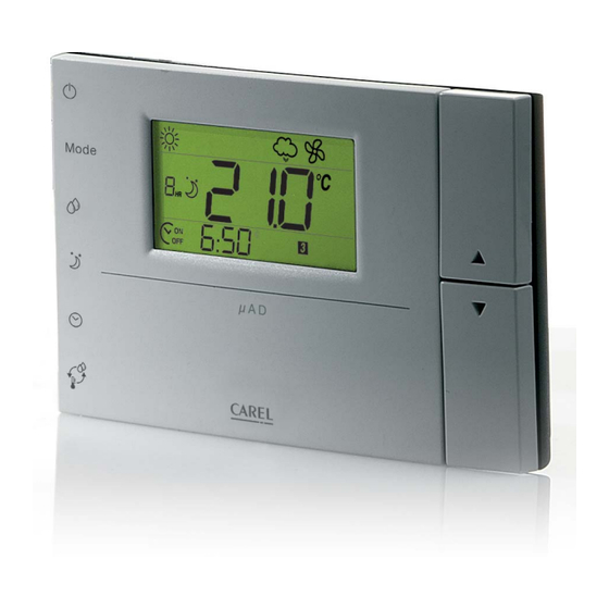
1 INTRODUZIONE 1.1 µAD Il terminale remoto µAD è un dispositivo elettronico per la regolazione di unità di condizionamento, gestite da controlli CAREL della serie ‘Micro Chiller 2’ (µC ) e ‘Micro Chiller 2 Second Edition’ (µC SE). µAD si contraddistingue per l’estetica accurata e per la facilità d’uso (diplay LCD di grandi dimensioni). -
Page 7: Installazione
2 INSTALLAZIONE 2.1 Istruzioni per il montaggio Attenzione: • Sezionare l’alimentazione prima di ogni intervento di installazione o manutenzione del µAD. • Il terminale deve essere fi ssato a muro in modo da permettere il ricircolo dell’aria attraverso le feritoie del guscio posteriore. -
Page 8: Connessioni Di Alimentazione
2.3 Connessioni di alimentazione Avvertenze: • I terminali di alimentazione del µAD sono chiamati G e G0. la connessione avviene tramite morsetti a vite a 2 vie fi ssati sul retro a muro dello strumento. • Il collegamenti elettrici devono essere eseguiti esclusivamente da un tecnico elettricista qualifi cato. •... -
Page 9: Interfaccia Utente
3 INTERFACCIA UTENTE 3.1 Tasti denom. descrizione POWER Commuta lo stato ON/STAND BY dell’intero sistema: Vedi par. 5.2 “FUNZIONE ON/STAND BY” Mode MODE Seleziona la modalità desiderata in funzione della confi gurazione del sistema e del modello di µAD: riscaldamento, raffreddamento, auto (funzionamento automatico), deumidifi... -
Page 10: Configurazione Del Sistema
4 CONFIGURAZIONE DEL SISTEMA 4.1 Tipologie di impianto • Impianto con µAD connesso con µC in modalità “Ambiente” Impostazioni dei parametri obbligatori: Parametro Pr01=0 Mode μAD on/off RS485 allarmi ambiente μCHILLER 2 CHILLER O POMPA DI CALORE Fig. 4.a • Impianto con µAD connesso con µC SE in modalità... -
Page 11: Avvertenze Preliminari
4.2 Avvertenze preliminari Prima di rendere operativo l’impianto è necessario verifi care quanto segue: - l’indirizzo seriale del µChiller (parametro H10) deve concidere con quello del µAD (parametro Ad01). Si POWER consiglia il valore di default Ad01=1 Mode µAD è confi gurato di default in modalità di funzionamento ‘Set Ambiente’, per modifi care in modalità ‘Pro- MODE cess’... -
Page 12: Funzioni Di Utilizzo
5 FUNZIONI DI UTILIZZO 5.1 Modi di funzionamento POWER µAD può gestire due modalità di funzionamento attraverso il parametro Pr01: Mode Pr01=0 regolazione SET POINT AMBIENTE, MODE Pr01=1 modalità PROCESS. 1 Regolazione Set point Ambiente (Pr01= 0) SLEEP μ A D Regola la temperatura ambiente misurata dalla sonda interna di µAD. -
Page 13: Set Point Temperatura
5.3 Set point temperatura POWER Per impostare la temperatura è necessario visualizzare ‘set’ a display (premere UP o DOWN). Mode MODE Per cambiare il set point premere i tasti UP o DOWN, quindi attendere 3 secondi senza premere alcun tasto. In caso di fasce orarie attive, la modifi... -
Page 14: Auto
5.6 Auto In modalità AUTO il sistema gestisce autonomamente la commutazione raffreddamento/riscaldamento. °C Per impostarla premere ripetutamente il tasto MODE fi no alla visualizzazione del simbolo AUTO sul display (fi g. 5.i). Questa modalità è disponibile solo con µC SE confi gurato come pompa di calore, o chiller con funziona- lità... -
Page 15: Funzione Sleep
5.10 Funzione sleep POWER La funzione sleep interviene sul valore di temperatura del set point, alzandolo in estate e abbassandolo in inverno. La variazione di temperatura permetterà un risparmio energetico notturno. Mode MODE Caratteristiche funzione sleep SLEEP • Può essere impostata per un tempo massimo di 9 ore consecutive, ed allo scadere del tempo prefi s- μ... -
Page 16: Regolazione Dell'orologio
5.12 Regolazione dell’orologio Requisiti (Fig 5.s) • µAD dotato di orologio RTC (Real Time Clock) • Parametro En01=1 (valore di default) Fig. 5.s Regolazione dell’orologio (Fig 5.s) • premere per 6 secondi il tasto CLOCK, a display compare “rtc” e l’ora corrente (lampeggiante), •... -
Page 17: Parametri E Allarmi
6 PARAMETRI E ALLARMI 6.1 Ripristino parametri di Default Per ripristinare i parametri di default premere per 5 secondi il tasto POWER durante la modalità di modi- fi ca parametri. L’impostazione dei default (inclusi set point ambiente se Pr01=0, set point umidità e offset night) verrà... -
Page 18: Tabella Parametri
Ht01: Differenziale temperatura Imposta il differenziale di regolazione della temperatura, Range: 0.5...10.0 (°C/°F), default: 3.0. Ht01 è utilizzato soltanto quando il µAD è collegato a µC ed il parametro Pr01=0, e defi nisce le soglie di accensione/standby del µC SE. Vedi par. 5.1 e 5.3 Hu01: Differenziale umidifi... - Page 19 Il µAD visualizza gli stati di allarme del chiller. Quando si verifi ca un allarme, nel display viene visualizzato il simbolo ALLARME lampeggiante (20) e, se il µAD è dotato di buzzer e En02=2, il buzzer inizia a suonare. E’ possibile tacitare il buzzer premendo il tasto TEMP per 3 secondi.
-
Page 20: Caratteristiche Tecniche
7 CARATTERISTICHE TECNICHE Tensione di alimentazione (secondo EN60730-1) 24 Vac ±15 %, 50/60 Hz 70 mA 1,5 VA oppure 31 Vdc ± 29 % 70 mA Classifi cazione secondo UL873: Ingresso alimentazione: 24 V ac, 50-60Hz, Class 2 25.5 - 36.25 V dc, Class 2 Power consumption, max 1 watt Uscite: serial link RS485, Class 2 Condizioni di funzionamento... - Page 21 User manual...
- Page 22 Warranty for the materials: 2 years (from the date of production, excluding the parts subject to wear). Type-approval: the quality and safety of Carel products are guaranteed by the ISO 9001 certifi ed design and production system, as well as the mark.
- Page 23 Index 1 INTRODUCTION 1.1 µAD ............................6 1.2 Models and main functions ....................6 1.3 Compatibility .......................... 6 1.4 Defi nitions and Abbreviations ....................6 2 INSTALLATION 2.1 Instructions for mounting ..................... 7 2.2 RS485 data line connections ....................7 2.3 Power supply connections ....................
- Page 24 Brief defi nition of most common terms and abbreviations: •µC : abbreviation of CAREL Micro Chiller 2. •µC SE: abbreviation of CAREL Micro Chiller 2 Second Edition. •Chiller: generator of cooled water. •Compensation: µAD function can be activated using the Co01 parameter, which intervenes on the µC SE compressor set.
- Page 25 2 INSTALLATION 2.1 Instructions for mounting Attention: • Isolate the power supply before any installation or maintenance intervention on the µAD. • The terminal must be fi xed to a wall to allow re-circulation of the air through the slots on the rear shell. Avoid places where the environmental temperature can alter, for example, outside walls, in the vicinity of doors leading to the outside or exposed to the sun.
- Page 26 2.3 Power supply connections Warning: • The power supply terminals of the µAD are called G and G0. The connection takes place by means of the 2-way screw clamps fi xed onto the back of the instrument. • The electric connections must be carried out exclusively by a qualifi ed electrician. •...
- Page 27 3 USER INTERFACE 3.1 Keys name description POWER Switches the ON/STAND BY state of the entire system: See par. 5.2 “ON/STAND BY FUNCTION” Mode MODE Select the desired mode depending on the confi guration of the system and the µAD model: heating, cooling, auto (automatic functioning), manual de-humidifi...
- Page 28 4 CONFIGURATION OF THE SYSTEM 4.1 Types of plant • Plant with µAD connected to µC in “Environment” mode Setting compulsory parameters: Parameter Pr01=0 Mode μAD on/off RS485 alarms environment μCHILLER 2 CHILLER OR HEAT PUMP Fig. 4.a •Plant with µAD connected to µC SE in “Enviroment”...
- Page 29 4.2 Preliminary warnings Before rendering the plant operational, the following must be checked: -the serial address of the µChiller (parameter H10) must coincide with that of the µAD (parameter Ad01). POWER Recommended default value Ad01=1 Mode µAD is confi gured in default in ‘Set Environment’ functioning mode. In order to modify in ‘Process’ mode, set MODE parameter Pr01=1 of the µAD (see par.
- Page 30 5 USER FUNCTIONS 5.1 Functioning modes POWER µAD can manage two functioning modes by means of the parameter Pr01: Mode Pr01=0 ENVIRONMENT SET POINT adjustment, MODE Pr01=1 PROCESS mode. 1 Environment Set point Adjustment (Pr01= 0) SLEEP μ A D Adjusts the environmental temperature measured by the µAD internal probe.
- Page 31 5.3 Temperature set point POWER To set the temperature is it necessary to display ‘set’ (press UP or DOWN). Mode MODE To change the set point press the UP or DOWN keys, then wait for 3 seconds without touching any key. If the time periods are active, the modifi...
- Page 32 5.6 Auto In AUTO mode the system autonomously manages cooling/heating switch over. °C To set it, repeatedly press the MODE button until the AUTO symbol is displayed (fi g. 5.i). This mode is only available with µC2SE confi gured as a heat pump or chiller with chiller with heating function.
- Page 33 5.10 Sleep function POWER The sleep function intervenes on the set point temperature value, raising it in the summer and lowering it in the winter. The temperature variation allows night-time energy saving. Mode MODE Sleep function features SLEEP • It can be set for a maximum time of 9 consecutive hours and on expiry of the pre-set time it deacti- μ...
- Page 34 5.12 Clock adjustment Requisites (Fig 5.s) • µAD with Real Time Clock • Parameter En01=1 (default value) Adjustment of the clock (Fig 5.s) Fig. 5.s • press the CLOCK key for 6 seconds, “rtc” and the current time (fl ashing) will appear on the display, •...
- Page 35 6 PARAMETERS AND ALARMS 6.1 Restore default parameters To restore default parameters press the POWER key for 5 seconds during the modify parameter mode. Setting defaults (including environment set point if Pr01=0, humidity set point and offset night) will be confi rmed with the simultaneous display of “Def”...
- Page 36 Ht01: Differential temperature Set the temperature adjustment differential, Range: 0.5...10.0 (°C/°F), default: 3.0. Ht01 is only used when the µAD is connected to µC and the parameter Pr01=0 and switch-on/standby threshold of the µC SE. See par. 5.1 and 5.3 Hu01: Humidify differential Sets the differential for the activation of the automatic humidifying function.
- Page 37 6.5 Alarms management The µAD displays the states of the chiller alarm. When an alarm occurs, the fl ashing ALARM symbol (20) is shown on the display. If the µAD has a buzzer and En02=2, the buzzer will emit a noise. The buzzer can be silenced by pressing the TEMP button for 3 seconds.
- Page 38 7 TECHNICAL FEATURES Power supply voltage (according to EN60730-1) 24 Vac ±15 %, 50/60 Hz 70 mA 1,5 VA or31 Vdc ± 29 % 70 mA Classifi cation according to UL873: Power supply input: 24 V ac, 50-60Hz, Class 2 25.5 - 36.25 V dc, Class 2 Power consumption, max 1 watt Output: serial link RS485, Class 2...
- Page 39 NOTE:...
- Page 40 NOTE:...
- Page 44 Agenzia / Agency: CAREL Industries HQs Via dell’Industria, 11 - 35020 Brugine - Padova (Italy) Tel. (+39) 049.9716611 - Fax (+39) 049.9716600 e-mail: carel@carel.com - www.carel.com...
Need help?
Do you have a question about the µAD and is the answer not in the manual?
Questions and answers