Table of Contents
Advertisement
Available languages
Available languages
Quick Links
Printed in Japan
HD Up-Converter
Board
設置説明書
2 ページ
Installation Instructions
Page 19
Manuel d'installation
Page 39
Installationsanleitung
Seite 59
Istruzioni per l'installazione
Instrucciones de instalación
お買い上げいただきありがとうございます。
電気製品は安全のための注意事項を守らないと、
火災や人身事故になることがあります。
• ご使用にあたっては、デジタルビデオカセットレコーダー本体
に付属の取扱説明書の「安全のために」と「
「
」をよくお読みください。お読みになったあとは、い
つでも見られるところに必ず保管してください。
• 本基板の取り付けは、必ずお買い上げ店またはソニーのサービ
ス窓口にご依頼ください。
DSBK-1820
© 2005 Sony Corporation
3-991-540-04(1)
JP
GB
FR
DE
IT
Pagina 79
ES
Pagina 99
」 、
Advertisement
Chapters
Table of Contents

Related Manuals for Sony DSBK-1820


Summary of Contents for Sony DSBK-1820
- Page 1 Page 19 Manuel d’installation Page 39 Installationsanleitung Seite 59 Istruzioni per l’installazione Pagina 79 Instrucciones de instalación Pagina 99 お買い上げいただきありがとうございます。 電気製品は安全のための注意事項を守らないと、 火災や人身事故になることがあります。 • ご使用にあたっては、デジタルビデオカセットレコーダー本体 に付属の取扱説明書の「安全のために」と「 」 、 「 」をよくお読みください。お読みになったあとは、い つでも見られるところに必ず保管してください。 • 本基板の取り付けは、必ずお買い上げ店またはソニーのサービ ス窓口にご依頼ください。 DSBK-1820 Printed in Japan © 2005 Sony Corporation...
- Page 2 日本語 目次 概要 ..................3 追加されるメニュー項目 ..........4 DSBK-1820 の構成品 ............11 お客様へ ................11 取り付け ................12 目次...
- Page 3 概要 HD アップコンバーターボード DSBK-1820 は、ソニーデジタル ビデオカセットレコーダー DSR-1800/1800A およびソニーデジ タルビデオカセットプレーヤー DSR-1600/1600A に装着して使 用するオプション基板です。 DSBK-1820(以下、本基板)の主な特長は以下のとおりです。 • DSR-1800/1800A および DSR-1600/1600A で再生される SD ビ デオ信号を HD ビデオ信号にアップコンバートして、2 系統 (DSR-1600/1600A は 1 系統)の HD SDI 出力を行います 。 HD SDI 出力信号には、アップコンバートされたビデオ信号 に同期したオーディオ(4 チャンネル)とタイムコードがエ ンベッドされます。 • DSR-1800/1800A へ装着した場合は、SD の入力信号をアップ...
-
Page 4: 追加されるメニュー項目
- i.LINK 入力からのアップコンバート、HD SDI 出力はでき ません。i.LINK 入力選択時は、EE モードになると、HD SDI 出力はミュートされます。 - タイムコードの入力は、タイムコード入力端子およびビデ オ信号に挿入されている VITC 信号に対応しています。 SDI 入力のエンベデッドタイムコード(RP188)には対応 していません。 - DSR-1800/1800A 本体のタイムコードの設定に従い、記録 するタイムコードと同じものが HD SDI にエンベッドされ ます。ビデオ信号と同期した外部タイムコード入力をエン ベッドするには、SYSTEM EE MODE を ON に設定し、 タイムコードの設定を EXT/REGEN に設定してください。 • 本基板を装着するためにはDSR-1800/1800AおよびDSR-1600/ 1600A のアップグレードが必要になります。 詳しくはお買い上げ店またはソニーのサービス窓口にお問い 合わせください。 お使いになる前に、必ず動作確認を行ってください。故障そ の他に伴う営業上の機会損失等は保証期間中および保証期間 経過後にかかわらず、補償はいたしかねますのでご了承くだ さい。... - Page 5 第 1 層 第 2 層 第 3 層 設定 UP LINE SELECT:HD SDI 1080i:1080i に設定 CONVERTER 出力のラインスタン する ダード変換(1080i/ 720P:720P に設定す 720P)を設定する。 る(59.94Hz のみ) ご注意 設定の変更は、次回の電 源投入時に有効になりま す。 TIME CODE:タイム 9P TC PHASE: SD:SD 出力位相に合 コードに関する設定 DSR-1800/1800A わせる をする。 および DSR-1600/ HD:HD 出力位相に合 1600A の RS-422A わせる リモート端子から のタイムコードセ ンスの応答の基準...
- Page 6 第 1 層 第 2 層 第 3 層 設定 SYNC PHASE (HD): COARSE:H シンク 0 〜 80H 〜 FFH HD SDI OUTPUT 端 位相を粗調整する 子に出力される HD FINE:H シンク位相を 0 〜 20H 〜 3FH ビデオ信号の H シン 微調整する ク位相を調整する。 ご注意 リファレンスビデオ入力 に対する HD SDI 出力の H シンク位相は、DSR- 1800/1800A、 DSR-1600/ 1600A 本体のシンク位相...
- Page 7 第 1 層 第 2 層 第 3 層 設定 UP CONV MODE:アッ EDGE-CROP:エッジ プコンバート時のア クロップモードを a) スペクト変換モード 選択する を選択する。 LETTER BOX:レ ターボックスモー b) ドを選択する SQUEEZE:スクイー ズモードを選択す c) る POSITION ADJUST:H H CROP:UP CONV 0 〜 20H 〜 3FH クロップやレター MODE で ボックスモードで元 「EDGE-CROP」 の画像から抜き出す が選択されている 位置を調整する。...
- Page 8 第 1 層 第 2 層 第 3 層 設定 UP CONV PROC:SD FIELD:フィールド画 を HD に変換すると 面を使用する。 き、元画像をどのよ FRAME:フレーム画 うに使用するかを選 面を使用する。 択する。 ADAPTIVE ( 標準 モード ):元の画 像の動きから判別 して、フレームま たはフィールドか ら変換する。 ADAPTIVE2 ( 静止 優先モード ):フ レームから変換す る割合を 「ADAPTIVE」よ り高く設定した モード。 ADAPTIVE3 ( 動き 優先モード ): フィールドから変 換する割合を 「ADAPTIVE」よ...
- Page 9 第 1 層 第 2 層 第 3 層 設定 IMAGE ENHANCER: DETAIL GAIN:輪郭 0 〜 20H 〜 3FH アップコンバーター 強調の鮮鋭度を設 のイメージエンハン 定する。 サーの調整を行う。 LIMITER:元信号を強 0 〜 10H 〜 1FH 調するために加算 されるディテール 信号の最大レベル を設定する。 CRISP THRES:小振 0 〜 8H 〜 FH 幅領域内で強調し ない振幅値を設定 する。...
- Page 10 第 1 層 第 2 層 第 3 層 設定 BG COLOR:アップコン BLACK:黒 バート出力時の素材 GRAY:グレー のない部分(バック BLUE:青 グラウンド)の色味 を設定する。 UP CONV MODE の設定と 4:3 から 16:9 への変換方法 a) EDGE-CROP 4:3 16:9 b) LETTER BOX 4:3 16:9 c) SQUEEZE 4:3 16:9 概要...
-
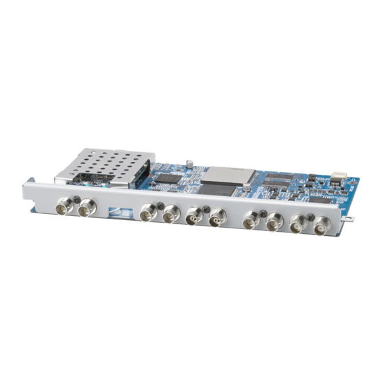
Page 11: Dsbk-1820 の構成品
DSBK-1820 の構成品 DSBK-1820 は、下図の品目で構成されています。 SDI-93 基板 HD SDI OUT 後面パネル用端子名称シール ネジ A(M3 × 3、銀色) ネジ B(M3 × 2、銀色) お客様へ 13 ページ以降の設置説明( 「取り付け」の項)は、お買い上げ 店およびソニーのサービス窓口用の設置説明書です。 お客様がこの設置説明書に記載された作業を行うと、火災や、 感電やけがなどの人身事故につながることがあります。 お客様自身では絶対に取り付け作業をしないでください。 本基板の取り付けは、必ずお買い上げ店またはソニーのサービ ス窓口にご依頼ください。 お客様へ... -
Page 12: 取り付け
取り付け DSBK-1820 を DSR-1800/1800A および DSR-1600/1600A に取 り付ける手順は、以下の通りです。 ご注意 DSBK-1820 の装着には、DSR-1800/1800A および DSR-1600/ 1600A 本体ファームウエアのバージョンアップが必要です。詳 しくはお買い上げ店またはソニーのサービス窓口にお問い合わ せください。 DSR-1600/1600A に取り付ける場合 本基板を DSR-1600/1600A に取り付ける場合は、以下の部品を 前もって取り外しておく必要があります。 • AES/EBU 入力端子 • SDI 入力端子 • HD SDI 端子の外側の BNC コネクター 取り外す手順は、以下の通りです。 SDI-93 基板から 4 本のハーネス (SDI 入力端子、 AES/EBU 入力端子)を取り外す(下図の... - Page 13 HD SDI 端子のコネクターパネルから、外側の BNC コネク ターとハーネスを取り外す。 コネクターパネル (HD SDI 端子) ハーネス 外側の BNC コネクター コネクターパネル(HD SDI 端子)を元の位置に取り付け (下図の 1) 、手順 で外したハーネスを SDI-93 基板上の 仮止めコネクターに接続する(下図の 2) 。 SDI-93 基板 ハーネス コネクターパネル (HD SDI 端子) (仮止めコネクター) 取り付け...
- Page 14 DSBK-1820 の取り付け(DSR-1800/1800A 、DSR-1600/ 1600A 共通) DSR-1800/1800A および DSR-1600/1600A(以下、本体)の 天板を外す。 本体の後面パネルからブランクパネル 3 枚を外す。 本体の後面 外す ブランクパネルの外しかた 後面パネルを取り外す。 取り付け...
- Page 15 後面パネル 本体の後面パネルの SDTI(QSDI) 表示部分が隠れるように、 同梱の後面パネル用端子名称シール(HD SDI OUT 表示) を貼る。 HD SDI OUT DV IN/OUT SDTI(QSDI) SDI-93 基板の取り付けネジ穴を、本体側の取り付けネジ穴 (5 箇所)に合わせる。 本体を上から見た図: 取り付けネジ穴(5 箇所) 後面パネル側 SDI-93 基板を本体に取り付ける。 5 つ目のネジ穴は TX-96 基板の下にあるため、次のよう に、一度 TX-96 基板を外してから取り付ける。 取り付け...
- Page 16 1 SDI-93 基板の中央部を押して、下側 にある端子と本体側の端子を接続す る。 本体の後面パネル側 SDI-93 基板 2 TX-96 基板の四隅のネジを外す。 TX-96 基板 取り付け...
- Page 17 3 TX-96 基板を上に持ち上げ、SDI-93 基板との接続を外 し、横にずらす。ネジ穴 I に同梱のネジ A を取り付け る。 ネジ A TX-96 基板 SDI-93 基板 ネジ穴 I 4 TX-96 基板を元の位置に戻して SDI-93 基板に接続し、 四隅をネジで固定する。 SDI-93 基板の残り 4 箇所にネジ A とネジ B を取り付け、 本体 に固定する。 取り付け...
- Page 18 ネジ B ネジ A 本体のリアパネルを元の位置に取り付け、最後に天板を取 り付ける。 取り付け...
- Page 19 Environments: E1 (residential), E2 (commercial and light industrial), E3 (urban outdoors), E4 (controlled EMC environment, ex. TV studio). The manufacturer of this product is Sony Corporation, 1-7-1 Konan, Minato-ku, Tokyo, Japan. The Authorized Representative for EMC and product safety is Sony Deutschland GmbH, Hedelfinger Strasse 61, 70327 Stuttgart, Germany.
- Page 20 Table of Contents Overview................21 Additional Menu Items ...........22 Components of the DSBK-1820 ........31 Installation................32 Table of Contents...
-
Page 21: Overview
2) SDI: SMPTE 259M compliant (D1 format, 270 Mbps) 3) AES/EBU: AES-3id-1995 compliant Notes • The DSBK-1820 cannot be used at the same time as the DSBK-1801/ 1601 or DSBK-1802/1602. • For the external reference signal, an HD 1125 bipolar tri-level sync signal is not supported. -
Page 22: Additional Menu Items
EXT/REGEN. • Installing this board requires a DSR-1800/1800P/1800A/1800AP or DSR-1600/1600P/1600A/1600AP upgrade. For details, contact your Sony dealer or a Sony service representative. Note Always verify that the unit is operating properly before use. SONY WILL NOT BE LIABLE FOR DAMAGES OF ANY KIND... - Page 23 Level 1 Level 2 Level 3 Settings LINE SELECT: Set 1080i: Select 1080i CONVERTER the line standard 720P: Select 720P conversion (59.94 Hz only) (1080i/720P) for HD SDI output. Notes • If the setting is changed, the new setting will be effective when the power is turned on after once turned...
- Page 24 Level 1 Level 2 Level 3 Settings TIME CODE: Set the 9P TC PHASE: Set SD: Set to SD output timecode the basis for phase settings. response to HD: Set to HD output timecode phase sensing through the DSR-1800/ 1800P/1800A/ 1800AP or DSR- 1600/1600P/ 1600A/1600AP...
- Page 25 Level 1 Level 2 Level 3 Settings SYNC PHASE (HD): COARSE: Make 0 - 80H - FFH Make coarse coarse adjustment of the adjustment of the H sync phase of H sync phase the HD video FINE: Make fine 0 - 20H - 3FH signal output adjustment of the from the HD SDI...
- Page 26 Level 1 Level 2 Level 3 Settings ASPECT FLAG: OFF: The up- Specify the converter mode treatment of an ignores the aspect ratio aspect ratio identification identification signal included signal, and within the SD follows setting of signal. UP CONV MODE.
- Page 27 Level 1 Level 2 Level 3 Settings POSITION ADJUST: H CROP: If “EDGE- 0 - 20H - 3FH Adjust the CROP” is position from selected in UP which the H crop CONV MODE, or letterbox mode adjust H crop image is (the horizontal extracted from position of the...
- Page 28 Level 1 Level 2 Level 3 Settings UP CONV PROC: FIELD: Use video When converting fields SD to HD, select FRAME: Use video how the original frames video is ADAPTIVE processed. (standard mode): Determine from movement in the original video whether to use frames or fields for conversion.
- Page 29 Level 1 Level 2 Level 3 Settings IMAGE ENHANCER: DETAIL GAIN: Set 0 - 20H - 3FH Adjust up- the sharpness of converter image edge enhancer. enhancement. LIMITER: Set the 0 - 10H - 1FH maximum level of the detail signal added to emphasize the original signal.
- Page 30 Level 1 Level 2 Level 3 Settings BG COLOR: Set the BLACK: Black background color GRAY: Gray for otherwise BLUE: Blue blank portions created in up- conversion. UP CONV MODE settings and methods of conversion from 4:3 to 16:9 a) EDGE-CROP 4 : 3 16 : 9 b) LETTER BOX...
-
Page 31: Components Of The Dsbk-1820
Components of the DSBK-1820 The DSBK-1820 consists of the following items. SDI-93 board HD SDI OUT Connector label for the rear panel Screw A (M3 × 3, silver-colored) Screw B (M3 × 2, silver-colored) Overview... -
Page 32: Installation
If this option is installed incorrectly, personal injury or damage to peripheral items may occur due to fire, shock, or other accidental circumstances. To avoid such risks, consult your Sony dealer or a Sony service representative for installation. To install the DSBK-1820 in the DSR-1800/1800P/1800A/1800AP or DSR-1600/1600P/1600A/1600AP, proceed as follows. - Page 33 Connector panel (SDI Input) Connector panel (HD SDI) Connector panel (AES/EBU Input) SDI-93 board Remove the outer BNC connector and the harness from the HD SDI connector panel. Connector panel (HD SDI) Harness Outer BNC connector Replace the HD SDI connector panel (see following figure 1), and connect the harness removed in step 2 to the temporary joint connector on the SDI-93 board (see following figure 2).
- Page 34 SDI-93 board Harness Connector panel (HD SDI) (Temporary joint connector) Installation of the DSBK-1820 (either in DSR-1800/1800P/1800A/1800AP or DSR-1600/1600P/1600A/ 1600AP) Remove the top panel of the DSR-1800/1800P/1800A/1800AP or DSR-1600/1600P/1600A/1600AP (hereinafter called the unit). Remove the three blank panels from the rear panel of the unit.
- Page 35 Rear panel of the unit Remove to install the DSBK-1820 How to remove a blank panel Remove the rear panel. Rear panel Affix the supplied connector label (HD SDI OUT) for the rear panel to cover the SDTI (QSDI) display portion of the rear panel.
- Page 36 Top view of the unit: Attachment screw Rear side of holes (5 holes) the unit Attach the SDI-93 board to the unit. The fifth screw hole is under the TX-96 board, so remove the board before attaching as shown below. 1Press down on the center of the SDI-93 board so as to connect the connectors of the board to the connectors of the unit.
- Page 37 2Remove the screws in all four corners of the TX-96 board. TX-96 board 3Lift up the TX-96 board, disconnect it from the SDI-93 board, and move it to the side. Fasten the supplied screw A in hole Screw A TX-96 board SDI-93 board Hole I...
- Page 38 Screw B Screw A Replace the rear panel of the unit, then the top panel. Installation...
- Page 39 Le fabricant de ce produit est Sony Corporation, 1-7-1 Konan, Minato- ku, Tokyo, Japon. Le représentant autorisé pour EMC et la sécurité des produits est Sony Deutschland GmbH, Hedelfinger Strasse 61, 70327 Stuttgart, Allemagne. Pour toute question concernant le service ou la garantie, veuillez consulter les adresses indiquées dans les documents de service...
- Page 40 Sommaire Aperçu..................41 Postes de menu additionnels ...........42 Composants de la DSBK-1820 ........51 Installation................52 Sommaire...
-
Page 41: Aperçu
2) SDI : compatible SMPTE 259M (format D1, 270 Mbps) 3) AES/EBU : compatible AES-3id-1995 Remarques • La DSBK-1820 ne peut pas s’utiliser en même temps que la DSBK- 1801/1601 ou la DSBK-1802/1602. • Le signal de synchro bi polaire trois niveaux HD 1125 n’est pas pris en charge pour le signal de référence externe. -
Page 42: Postes De Menu Additionnels
1800P/1800A/1800AP ou DSR-1600/1600P/1600A/1600AP. L’installation de cette carte exige une mise à niveau du micrologiciel de l’enregistreur de disque. Pour les détails, contactez votre distributeur Sony ou un représentant du service après-vente Sony. Remarque Vérifiez toujours que l’appareil fonctionne correctement avant l’utilisation. - Page 43 Niveau 1 Niveau 2 Niveau 3 Réglages LINE SELECT: Règle 1080i: Sélectionne CONVERTER la conversion de 1080i ligne standard 720P: Sélectionne (1080i/720P) 720P (59,94 Hz pour la sortie HD uniquement) SDI. Remarques • Si le réglage est modifié, le nouveau réglage prendra effet après que le système ait été...
- Page 44 Niveau 1 Niveau 2 Niveau 3 Réglages TIME CODE: Réglez 9P TC PHASE: Régle SD: Régle sur la le paramètre du la base pour la phase de sortie code temporel. réponse à la détection du HD: Régle sur la code temporel à phase de sortie travers le connecteur...
- Page 45 Niveau 1 Niveau 2 Niveau 3 Réglages SYNC PHASE (HD): COARSE: Effectue 0 - 80H - FFH Effectue un un réglage réglage approximatif de approximatif de la phase de la phase de synchro H synchro H du FINE: Effectue un 0 - 20H - 3FH signal vidéo HD réglage précis de...
- Page 46 Niveau 1 Niveau 2 Niveau 3 Réglages ASPECT FLAG: OFF: Le mode Spécifie le convertisseur traitement du élévateur ignore signal le signal d’identification du d’identification du rapport d’aspect rapport d’aspect, compris dans le et suit le signal SD. paramètre de UP CONV MODE.
- Page 47 Niveau 1 Niveau 2 Niveau 3 Réglages POSITION ADJUST: H CROP: Si « EDGE- 0 - 20H - 3FH Ajustez la CROP » est position à partir sélectionné au de laquelle poste de UP l’image du mode CONV MODE, H crop ou ajuste H crop (la letterbox est position...
- Page 48 Niveau 1 Niveau 2 Niveau 3 Réglages UP CONV PROC: FIELD: Utilise les Lors de la trames vidéo conversion SD à FRAME: Utilise les HD, sélectionne cadres vidéo le traitement de ADAPTIVE (mode la vidéo originale. standard): Détermine l’utilisation de cadres ou de trames pour la conversion à...
- Page 49 Niveau 1 Niveau 2 Niveau 3 Réglages IMAGE ENHANCER: DETAIL GAIN: Ajuste 0 - 20H - 3FH Ajuste le le rehausseur rehausseur d’image du d’image du convertisseur convertisseur élévateur. élévateur. LIMITER: Règle le 0 - 10H - 1FH niveau maximum du signal de détail ajouté...
- Page 50 Niveau 1 Niveau 2 Niveau 3 Réglages BG COLOR: Règle la BLACK: Noir couleur du fond GRAY: Gris pour les autres BLUE: Bleu zones vides créées en conversion élévatrice. Paramètres UP CONV MODE et méthodes de conversion du format 4:3 au 16:9 a) EDGE-CROP 4 : 3 16 : 9...
-
Page 51: Composants De La Dsbk-1820
Composants de la DSBK-1820 La carte DSBK-1820 comprend les éléments suivants. Carte SDI-93 HD SDI OUT Etiquette de connecteur pour la plaque arrière Vis A (M3 × 3, argentées) Vis B (M3 × 2, argentées) Aperçu... -
Page 52: Installation
à des blessures ou à des dommages pour les éléments périphériques. Pour éviter de tels risques, consultez votre distributeur Sony ou agent de service Sony pour l’installation. Procédez comme suit pour installer la carte DSBK-1820 dans le DSR- 1800/1800P/1800A/1800AP ou DSR-1600/1600P/1600A/1600AP. Remarque L’installation de la DSBK-1820 requiert une mise à... - Page 53 Plaque à connecteurs (Entrée SDI) Plaque à connecteurs (HD SDI) Plaque à connecteurs (Entrée AES/EBU) Carte SDI-93 Retirez le connecteur BNC extérieur et le câblage de la plaque à connecteurs HD SDI. Plaque à connecteurs (HD SDI) Câblage Connecteur BNC extérieur Replacez la plaque à...
- Page 54 Plaque à connecteurs (HD SDI) CN1 (Connecteur de jonction temporaire) Installation de la DSBK-1820 (soit dans le DSR-1800/1800P/1800A/ 1800AP soit dans le DSR-1600/1600P/1600A/1600AP) Retirez la plaque supérieure du DSR-1800/1800P/1800A/1800AP ou du DSR-1600/1600P/1600A/1600AP (appelé unité par la suite). Retirez les trois plaques de suppression de la plaque arrière de l’unité.
- Page 55 Retirez pour installer la Plaque arrière de DSBK-1820 l’unité Comment retirer la plaque de suppression Retirez la plaque arrière. Plaque arrière Apposez l’étiquette de connecteur fournie (HD SDI OUT) pour la plaque arrière pour couvrir la portion de SDTI (QSDI) de la plaque arrière.
- Page 56 Alignez les cinq orifices de vis de la carte SDI-93 avec ceux de l’unité. Vue du dessus de l’unité: Fixation dans les orifices Face arrière de de vis (5 orifices) l’unité Fixez la carte SDI-93 à l’unité. Le cinquième orifice de vis se trouve sous la carte TX-96, donc vous devez retirer la carte avant de la fixation comme indiqué...
- Page 57 2Retirez les vis des quatres coins de la carte TX-96. Carte TX-96 3Soulevez la carte TX-96, retirez-la de la carte SDI-93 et mettez-la sur le côté. Fixez la vis A fournie dans l’orifice I. Vis A Carte TX-96 Carte SDI-93 Orifice I 4Replacez la carte TX-96 de façon à...
- Page 58 Vis B Vis A Replacez la plaque arrière de l’unité puis la plaque supérieure. Installation...
- Page 59 (Wohnbereich), E2 (kommerzieller und in beschränktem Maße industrieller Bereich), E3 (Stadtbereich im Freien) und E4 (kontrollierter EMV-Bereich, z.B. Fernsehstudio). Der Hersteller dieses Produkts ist Sony Corporation, 1-7-1 Konan, Minato-ku, Tokyo, Japan. Der autorisierte Repräsentant für EMV und Produktsicherheit ist Sony Deutschland GmbH, Hedelfinger Strasse 61, 70327 Stuttgart, Deutschland.
- Page 60 Inhaltsverzeichnis Kurzbeschreibung..............61 Weitere Menüpositionen ..........62 Bestandteile der DSBK-1820 .........71 Einbau..................72 Inhaltsverzeichnis...
-
Page 61: Kurzbeschreibung
Aufwärtswandlung des SD-Eingangssignals auf eine HD SDI- Ausgabe möglich. Dies unterliegt jedoch einigen Einschränkungen: lesen Sie die folgenden „Hinweise”. • Die Karte DSBK-1820 bietet die ganze Funktionalität, über die die Optionskarten DSBK-1801 und DSBK-1601 verfügen. Sie unterstützt die Eingabe und Ausgabe von SD SDI -Signalen (serial digital interface;... -
Page 62: Weitere Menüpositionen
Wenden Sie sich für nähere Einzelheiten an Ihren Sony-Händler oder Sony-Service-Mitarbeiter. Hinweis Bestätigen Sie vor dem Gebrauch immer, dass das Gerät richtig arbeitet. SONY KANN KEINE HAFTUNG FÜR SCHÄDEN JEDER ART, EINSCHLIESSLICH ABER NICHT BEGRENZT AUF KOMPENSATION ODER ERSTATTUNG, AUFGRUND VON VERLUST VON AKTUELLEN ODER ERWARTETEN PROFITEN DURCH FEHLFUNKTION DIESES GERÄTS ODER... - Page 63 Level 1 Level 2 Level 3 Einstellungen LINE SELECT: 1080i: Zur Wahl von CONVERTER Einstellung der 1080i Standard- 720P: Zur Wahl von Zeilenumwand- 720P (nur 59,94 lung (1080i/ 720P) für die HD SDI-Ausgabe. Hinweise • Bei Änderung der Einstellung wird die neue Einstellung übernommen, nachdem der Strom...
- Page 64 Level 1 Level 2 Level 3 Einstellungen TIME CODE: 9P TC PHASE: SD: Einstellung der Nehmen Sie die Stellen Sie über Timecode- Ausgabephase Einstellungen Fernanschluss HD: Einstellung der vor. RS-422A des DSR-1800/ Ausgabephase 1800P/1800A/ 1800AP oder 1600/1600P/ 1600A/1600AP die Grundlage Berücksichtigung des Timecode- Tasters ein.
- Page 65 Level 1 Level 2 Level 3 Einstellungen SYNC PHASE (HD): COARSE: Vornahme 0 - 80H - FFH Vornahme der Grobeinstellung Grobeinstellung der H-Synchro- der H- nisationsphase Synchronisa- des vom HD SDI tionsphase OUTPUT- FINE: Vornahme der 0 - 20H - 3FH Anschluss Feineinstellung ausgegebenen...
- Page 66 Level 1 Level 2 Level 3 Einstellungen ASPECT FLAG: OFF: Der Spezifizierung Aufwärtswand- des Vorgehens lungsmodus bei einem im SD- ignoriert das Signal Seitenverhältnis- vorhandenen Bestimmungs- Seitenverhältnis- signal und richtet Bestimmungs- sich nach der signal. Einstellung von UP CONV MODE. Hinweis ON: Der Wenn das...
- Page 67 Level 1 Level 2 Level 3 Einstellungen POSITION ADJUST: H CROP: Wenn unter 0 - 20H - 3FH Stellen Sie die UP CONV Position ein, von MODE „EDGE der aus das H- CROP“ gewählt Schnitt- oder ist, Einstellung Letterbox- des H-Schnitts Modus-Bild des (die horizontale Originalvideos...
- Page 68 Level 1 Level 2 Level 3 Einstellungen UP CONV PROC: FIELD: Verwendung Wahl der Verarbeitung des Videohalbbildern Originalvideos FRAME: Verwendung bei der Umwandlung von Videovollbildern SD zu HD. ADAPTIVE (Standardmo- dus): Festlegung auf Grund der Bewegung im Originalvideo, ob Voll- oder Halbbilder für die Wandlung verwendet...
- Page 69 Level 1 Level 2 Level 3 Einstellungen IMAGE ENHANCER: DETAIL GAIN: 0 - 20H - 3FH Einstellung der Einstellung der Aufwärtswand- Schärfe der lungs-Bildverbes- Randverbesse- serung. rung. LIMITER: Einstellung 0 - 10H - 1FH Höchstniveaus Einzelsignals, das zur Verstärkung des Originalsignals hinzugefügt wird.
- Page 70 Level 1 Level 2 Level 3 Einstellungen H/V RATIO: 0 - 03H - 7H Einstellung des horizontalen/ vertikalen Verhältnisses für die Randverbes- serung. GAMMA LEVEL: 0 - 08H - 10H Einstellung der Steigung der Gamma- Kompensations- kurve. BG COLOR: BLACK: Schwarz Einstellung der GRAY: Grau Hintergrundfar-...
-
Page 71: Bestandteile Der Dsbk-1820
Bestandteile der DSBK-1820 Die DSBK-1820 weist folgende Bestandteile auf. Leiterplatte SDI-93 HD SDI OUT Anschlussetikett für die Rückseite Schraube A (M3 × 3, Schraube B (M3 × 2, silberfarben) silberfarben) Kurzbeschreibung... -
Page 72: Einbau
Schlag oder anderweitigen Problemen. Wenden Sie sich zum Einbau daher an Ihren Sony-Händler oder Sony-Service- Mitarbeiter. Verfahren Sie zum Einbau der DSBK-1820 in den DSR-1800/1800P/ 1800A/1800AP oder DSR-1600/1600P/1600A/1600AP wie folgt. Hinweis Zum Einbau der DSBK-1820 muss die Geräte-Firmware des DSR- 1800/1800P/1800A/1800AP oder DSR-1600/1600P/1600A/1600AP aktualisiert werden. - Page 73 Anschlussfeld (SDI-Eingang) Anschlussfeld (HD SDI) Anschlussfeld (AES/ EBU-Eingang) Leiterplatte SDI-93 Entfernen Sie den äußerer BNC-Anschluss und den Kabelbaum vom HD SDI-Anschlussfeld. Anschlussfeld (HD SDI) Kabelbaum Äußerer BNC-Anschluss Bringen Sie das HD SDI-Anschlussfeld an (siehe folgende Abbildung 1) und schließen Sie den im Schritt 2 entfernten Kabelbaum an den temporären gemeinsamen Anschluss auf der Karte SDI-93 an (siehe folgende Abbildung 2).
- Page 74 Leiterplatte SDI-93 Kabelbaum Anschlussfeld (HD SDI) CN1 (Temporärer gemeinsamer Anschluss) Einbau der DSBK-1820 (entweder in den DSR-1800/1800P/1800A/ 1800AP oder DSR-1600/1600P/1600A/1600AP) Entfernen Sie die obere Platte des DSR-1800/1800P/1800A/ 1800AP oder DSR-1600/1600P/1600A/1600AP (im Folgenden als „Gerät“ bezeichnet). Entfernen Sie die drei Blindplatten von der Rückseite des Geräts.
- Page 75 Entfernen, um die DSBK-1820 einzubauen Rückseite des Geräts Entfernen einer Blindplatte Entfernen Sie die Rückseite. Rückseite Befestigen Sie das mitgelieferte Anschlussetikett (HD SDI OUT) für die Rückseite, um die SDTI- (QSDI-) Anzeigefelder der Rückseite abzudecken. HD SDI OUT DV IN/OUT SDTI(QSDI) Gleichen Sie alle fünf Befestigungslöcher der Karte SDI-93 mit...
- Page 76 Obere Geräteansicht: Angebrachte Befestigungslöcher Rückseite des (5 Löcher) Geräts Bringen Sie die Karte SDI-93 an das Gerät an. Das fünfte Befestigungsloch ist unter der Leitplatte TX-96, entfernen Sie also die Leitplatte vor dem unten beschriebenen Anbringen. 1Drücken Sie auf die Mitte der Karte SDI-93, so als würden Sie die Anschlüsse der Karte mit den Anschlüssen des Geräts verbinden.
- Page 77 2Entfernen Sie die Schrauben in allen vier Ecken der Leitplatte TX-96. Leiterplatte TX-96 3Heben Sie die Leitplatte TX-96 an, lösen Sie die Verbindung zur Karte SDI-93 und schieben Sie sie zur Seite. Befestigen Sie die mitgelieferte Schraube A im Loch I. Schraube A Leiterplatte TX-96 Leiterplatte...
- Page 78 Schraube B Schraube A Bringen Sie zuerst die Rückseite des Geräts und dann die obere Platte wieder an. Einbau...
- Page 79 E1 (residenziali), E2 (commerciali e industriali leggeri), E3 (esterni urbani) e E4 (ambienti EMC controllati, ad esempio studi televisivi). Il fabbricante di questo prodotto è la Sony Corporation, 1-7-1 Konan, Minato-ku, Tokyo, Giappone. La rappresentanza autorizzata per EMC e la sicurezza dei prodotti è la Sony Deutschland GmbH, Hedelfinger Strasse 61, 70327 Stoccarda, Germania.
- Page 80 Indice Descrizione................81 Voci di menu supplementari ...........82 Componenti del DSBK-1820 ..........91 Installazione................92 Indice...
-
Page 81: Descrizione
Descrizione La scheda DSBK-1820 per la conversione a HD è una scheda opzionale che si può installare nei videoregistratori digitali Sony DSR-1800/ 1800P/1800A/1800AP o nei lettori digitali di videocassette Sony DSR- 1600/1600P/1600A/1600AP. Le caratteristiche principali di questa scheda sono descritte di seguito. -
Page 82: Voci Di Menu Supplementari
Sony o il rappresentante Sony. Nota Verificare sempre che l’apparecchio stia funzionando correttamente prima di usarlo. LA SONY NON SARÀ RESPONSABILE DI DANNI DI QUALSIASI TIPO, COMPRESI, MA SENZA LIMITAZIONE A, RISARCIMENTI O RIMBORSI A CAUSA DELLA PERDITA DI PROFITTI ATTUALI O PREVISTI DOVUTA A GUASTI DI QUESTO APPARECCHIO, SIA DURANTE IL PERIODO DI VALIDITÀ... - Page 83 Livello 1 Livello 2 Livello 3 Impostazioni LINE SELECT: 1080i: Seleziona CONVERTER Imposta la 1080i conversione di 720P: Seleziona linea standard 720P (solo 59,94 (1080i/720P) per l’emissione HD SDI. Note • Se si cambia l’impostazione, la nuova impostazione sarà disponibile dopo aver spento e riacceso l’apparato.
- Page 84 Livello 1 Livello 2 Livello 3 Impostazioni TIME CODE: 9P TC PHASE: SD: Imposta la fase di Impostare le Impostare la uscita SD impostazioni del base di risposta HD: Imposta la fase codice del tempo. alla rilevazione di uscita HD del codice di tempo attraverso il connettore...
- Page 85 Livello 1 Livello 2 Livello 3 Impostazioni SYNC PHASE (HD): COARSE: Effettua 0 - 80H - FFH Effettua una una regolazione regolazione grossolana della grossolana della fase di fase di sincronizzazione sincronizzazione H per l’uscita del FINE: Effettua una 0 - 20H - 3FH segnale video regolazione HD dal...
- Page 86 Livello 1 Livello 2 Livello 3 Impostazioni ASPECT FLAG: OFF: Il modo di Specifica il conversione trattamento di un ignora il segnale segnale di di identificazione identificazione di del rapporto di rapporto di formato, e segue formato incluso l’impostazione di con il segnale UP CONV MODE.
- Page 87 Livello 1 Livello 2 Livello 3 Impostazioni POSITION ADJUST: H CROP: Se nella 0 - 20H - 3FH Regolare la voce di UP posizione dalla CONV MODE si quale il taglio H o è selezionato formato lettera “EDGE-CROP”, dell’immagine regolare il taglio viene estratto dal H (la posizione video originale.
- Page 88 Livello 1 Livello 2 Livello 3 Impostazioni UP CONV PROC: FIELD: Usa i campi Quando si video converte SD a FRAME: Usa i HD, selezionare fotogrammi video come viene ADAPTIVE (modo processato il standard): video originale. Determina dal movimento del video originale se si usa fotogrammi o...
- Page 89 Livello 1 Livello 2 Livello 3 Impostazioni IMAGE ENHANCER: DETAIL GAIN: 0 - 20H - 3FH Regola Imposta la l’intensificatore nitidezza della conversione dell’aumento del dell’immagine. bordo. LIMITER: Imposta il 0 - 10H - 1FH livello massimo del segnale particolare aggiunto per accentuare il segnale...
- Page 90 Livello 1 Livello 2 Livello 3 Impostazioni H/V RATIO: Imposta 0 - 03H - 7H il rapporto orizzontale/ verticale per l’aumento del bordo. GAMMA LEVEL: 0 - 08H - 10H Regola l’inclinazione della curva della gamma di compensazione. BG COLOR: Imposta BLACK: Nero il colore di fondo GRAY: Grigio...
-
Page 91: Componenti Del Dsbk-1820
Componenti del DSBK-1820 Il DSBK-1820 si compone delle seguenti parti. Scheda SDI-93 HD SDI OUT Etichetta del connettore per il pannello posteriore Vite A (M3 × 3, color argento) Vite B (M3 × 2, color argento) Descrizione... -
Page 92: Installazione
DSR-1800/1800P/1800A/1800AP o DSR-1600/1600P/1600A/1600AP. L’installazione di questa scheda richiede un aggiornamento del firmware del registratore di dischi. Per dettagli, contattare il proprio rivenditore Sony o il rappresentante Sony. Installazione nel DSR-1600/1600P/1600A/1600AP Prima di installare il DSBK-1820 nel DSR-1600/1600P/1600A/ 1600AP, si devono rimuovere le seguenti parti. - Page 93 Pannello del connettore (entrata SDI) Pannello del connettore (HD SDI) Pannello del connettore (entrata AES/EBU) Scheda SDI-93 Rimuovere il connettore di uscita BNC e l’imbracatura dal pannello del connettore HD SDI. Pannello del connettore (HD SDI) Cablaggio Connettore di uscita BNC Riporre il pannello del connettore HD SDI (vedere la seguente illustrazione 1) e collegare l’imbracatura rimossa al passo 2 al connettore di unione temporaneo sulla scheda SDI-93 (vedere la...
- Page 94 Cablaggio Pannello del connettore (HD SDI) CN1 (Connettore di unione temporaneo) Installazione del DSBK-1820 (sia per DSR-1800/1800P/1800A/ 1800AP che DSR-1600/1600P/1600A/1600AP) Rimuovere il pannello superiore del DSR-1800/1800P/1800A/ 1800AP o DSR-1600/1600P/1600A/1600AP (d’ora in poi chiamato unità). Rimuovere i tre pannelli ciechi dal pannello posteriore dell’unità.
- Page 95 Pannello posteriore Rimuovere per installare il dell’unità DSBK-1820 Come rimuovere il pannello cieco Rimuovere il pannello posteriore. Pannello posteriore Attaccare l’etichetta del connettore fornita (HD SDI OUT) per il pannello posteriore per coprire la parte del display SDTI (QSDI) del pannello posteriore.
- Page 96 Vista dall’alto dell’unità: Buchi delle viti di Lato posteriore attacco (5 buchi) dell’unità Attaccare la scheda SDI-93 all’unità. Il quinto buco della vite si trova sotto la scheda TX-96, quindi rimuovere la scheda prima di attaccare come mostrato sotto. 1Premere sul centro della scheda SDI-93 in modo tale da collegare i connettori della scheda ai connettori dell’unità.
- Page 97 2Rimuovere le viti dai quattro angoli della scheda TX-96. Scheda TX-96 3Sollevare la scheda TX-96, scollegarla dalla scheda SDI-93 e muoverla sul lato. Avvitare la vite A fornita nel buco I. Vite A Scheda TX-96 Scheda SDI-93 Buco I 4Riporre la scheda TX-96 collegata alla scheda SDI-93 e avvitare le viti ai quattro angoli.
- Page 98 Vite B Vite A Riporre il pannello posteriore dell’unità, quindi il pannello superiore. Installazione...
- Page 99 E3 (exteriores urbanos), y E4 (entorno con EMC controlada, p. ej., estudio de televisión). El fabricante de este producto es Sony Corporation, con dirección en 1- 7-1 Konan, Minato-ku, Tokio, Japón. El Representante autorizado para EMC y seguridad del producto es Sony Deutschland GmbH, Hedelfinger Strasse 61, 70327 Stuttgart, Alemania.
- Page 100 Índice Descripción general ............101 Opciones adicionales del menú ........102 Componentes de la tarjeta DSBK-1820 ......111 Instalación ................112 Índice...
-
Page 101: Descripción General
2) SDI: cumple con SMPTE 259M (formato D1, 270 Mbps) 3) AES/EBU: cumple con AES-3id-1995 Notas • La DSBK-1820 no se puede utilizar al mismo tiempo que la DSBK- 1801/1601 o la DSBK-1802/1602. • No es compatible con una señal de sincronización bipolar a tres niveles HD 1125 en el caso de las señales de referencia externas. -
Page 102: Opciones Adicionales Del Menú
La instalación de esta tarjeta requiere una mejora del firmware de la grabadora. Para más información, póngase en contacto con su distribuidor de Sony o el servicio de asistencia de Sony. Nota Verifique siempre que esta unidad funciona correctamente antes de utilizarlo. - Page 103 Nivel 1 Nivel 2 Nivel 3 Ajustes LINE SELECT: 1080i: Selecciona CONVERTER Ajusta la 1080i conversión 720P: Selecciona estándar de la 720P (sólo 59,94 línea (1080i/ 720P) para la salida HD SDI. Notas • Si se cambia el ajuste, el nuevo ajuste será...
- Page 104 Nivel 1 Nivel 2 Nivel 3 Ajustes TIME CODE: Ajuste 9P TC PHASE: SD: Ajustado a la el código de Ajusta los fase de salida SD tiempo. fundamentos de HD: Ajustado a la respuesta para el fase de salida detector de código de tiempo mediante el conector remoto...
- Page 105 Nivel 1 Nivel 2 Nivel 3 Ajustes SYNC PHASE (HD): COARSE: Realiza un 0 - 80H - FFH Realiza un ajuste ajuste general de general de la la fase de fase de sincronización de sincronización de H en la salida de FINE: Realiza un 0 - 20H - 3FH la señal de vídeo...
- Page 106 Nivel 1 Nivel 2 Nivel 3 Ajustes ASPECT FLAG: OFF: El modo del Indica el convertidor tratamiento de ignora la señal una señal de de identificación identificación de de la relación de la relación de aspecto, y aspecto incluida mantiene los en la señal SD.
- Page 107 Nivel 1 Nivel 2 Nivel 3 Ajustes POSITION ADJUST: H CROP: Si está 0 - 20H - 3FH Ajuste la posición seleccionado desde la cual la “EDGE-CROP” imagen del modo en UP CONV buzón o de MODE, ajusta el recorte H se recorte H (la extrae del vídeo posición...
- Page 108 Nivel 1 Nivel 2 Nivel 3 Ajustes UP CONV PROC: FIELD: Utiliza Cuando campos de vídeo convierta SD en FRAME: Utiliza HD, selecciona el fotogramas de modo de vídeo procesado del ADAPTIVE (modo vídeo original. estándar): Determina a través del movimiento del vídeo original si utilizar...
- Page 109 Nivel 1 Nivel 2 Nivel 3 Ajustes IMAGE ENHANCER: DETAIL GAIN: Ajusta 0 - 20H - 3FH Ajusta el la nitidez para optimizador de mejorar el borde. imágenes del LIMITER: Ajusta el 0 - 10H - 1FH convertidor. nivel máximo de la señal de detalle agregada para realzar la...
- Page 110 Nivel 1 Nivel 2 Nivel 3 Ajustes BG COLOR: Ajusta BLACK: Negro el color del fondo GRAY: Gris de las porciones BLUE: Azul en blanco que se hayan generado con la conversión. Ajustes de UP CONV MODE y de los métodos de conversión de 4:3 a 16:9 a) EDGE-CROP 4 : 3 16 : 9...
-
Page 111: Componentes De La Tarjeta Dsbk-1820
Componentes de la tarjeta DSBK-1820 La tarjeta DSBK-1820 contiene los siguientes elementos. Tarjeta SDI-93 HD SDI OUT Etiqueta de conexión del panel posterior Tornillo A (M3 × 3, plateados) Tornillo B (M3 × 2, plateados) Descripción general... -
Page 112: Instalación
Para evitar estos riesgos, póngase en contacto con su representante de Sony o el servicio técnico de Sony para la instalación. Para instalar la tarjeta DSBK-1820 en la videograbadora DSR-1800/ 1800P/1800A/1800AP o DSR-1600/1600P/1600A/1600AP, siga las siguientes instrucciones. - Page 113 Panel de conexiones (entrada SDI) Panel de conexiones (HD SDI) Panel de conexiones (entrada AES/EBU) Tarjeta SDI-93 Extraiga el conector BNC exterior y el mazo de cables del panel de conexiones HD SDI. Panel de conexiones (HD SDI) Mazo de cables Conector BNC exterior Sustituya el panel de conexiones HD SDI (véase siguiente figura 1) y conecte el mazo extraído en el paso 2 al conector de empalme...
- Page 114 Panel de conexiones (HD SDI) CN1 (Conector de empalme temporal) Instalación de la DSBK-1820 (ya sea en DSR-1800/1800P/1800A/ 1800AP o en DSR-1600/1600P/1600A/1600AP) Extraiga el panel superior de la DSR-1800/1800P/1800A/1800AP o de la DSR-1600/1600P/1600A/1600AP (llamada la unidad a partir de aquí).
- Page 115 Panel posterior de la Extraiga para instalar la DSBK-1820 unidad Cómo extraer un panel ciego Extraiga el panel posterior. Panel posterior Fije la etiqueta de conexión suministrada (HD SDI OUT) al panel posterior para cubrir la parte de visualización SDTI (QSDI) del panel trasero.
- Page 116 Vista superior de la unidad: Orificios para tornillos Lado posterior de sujeción (5 orificios) de la unidad Fije la tarjeta SDI-93 de la unidad. El quinto orificio para tornillo se encuentra bajo la tarjeta TX-96, de modo que extraiga la tarjeta antes de acoplarla tal y, como se muestra a continuación.
- Page 117 2Extraiga los tornillos de las cuatro esquinas de la tarjeta TX-96. Tarjeta TX-96 3Levante la tarjeta TX-96, desconéctela de la tarjeta SDI-93 y desplácela a un lado. Fije el tornillo suministrado A en el orificio I. Tornillo A Tarjeta TX-96 Tarjeta SDI-93 Orificio I...
- Page 118 Tornillo B Tornillo A Sustituya el panel posterior de la unidad y, a continuación, el panel superior. Instalación...