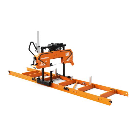
Wood-mizer LX25 Safety, Operation, Maintenance & Parts Manual
Sawmill
Hide thumbs
Also See for LX25:
- Safety, operation, maintenance & parts manual (91 pages) ,
- Maintenance manual (70 pages)

Related Manuals for Wood-mizer LX25


Summary of Contents for Wood-mizer LX25
- Page 1 LX25 Sawmill Safety, Operation, Maintenance, & Parts Manual LX25G9 rev. A1.01 LX25G7 rev. A1.01 Safety is our #1 concern! May 2020 Form #2426 WARNING! Read and understand this manual before using this machine.
- Page 2 Active Patents assigned to Wood-Mizer, LLC Wood-Mizer, LLC has received patents that protect our inventions which are a result of a dedication to research, innovation, development, and design. Learn more at: woodmizer.com/patents ©2021 Wood-Mizer LLC Printed in the United States of America, all rights reserved. No part of this manual may be reproduced in any form by any...
-
Page 3: Table Of Contents
Transporting the Sawmill..................4-8 SECTION 5 MAINTENANCE Continuous maintenance ..................5-1 General maintenance................... 5-1 Engine maintenance .................... 5-1 SECTION 6 SAWHEAD PARTS Sliding Blade Guide Arm Assembly..............6-1 Blade Guide Assembly..................6-2 Clutch Assembly ....................6-4 Table of Contents LX25 8/25/21... - Page 4 Kohler 9hp Gas Engine ..................7-1 Kohler 7hp Gas Engine ..................7-2 SECTION 8 BED AND CARRIAGE ASSEMBLY Bed........................8-1 Log Clamp ......................8-2 Carriage ......................8-3 Log Rest.......................8-5 Optional Log Ramps....................8-6 Optional Adjustable Feet..................8-7 ..........................8-8 Optional Log Taper Wedge ................8-9 LX25 8/25/21 Table of Contents...
-
Page 5: Section 1 Introduction
SECTION 1 INTRODUCTION About This Manual ® This manual replaces any previous information received on your Wood-Mizer equipment. The information and instructions in this manual do not amend or extend the limited warranties for the equipment given at the time of purchase. -
Page 6: Section 2 Safety
The procedures listed in this manual may not include all ANSI, OSHA, or locally required safety procedures. It is the owner/operator’s responsibility and not Wood-Mizer LLC to ensure all operators are properly trained and informed of all safety protocols. Owner/Operators are responsible for following all safety procedures when operating and performing maintenance to the equipment. - Page 7 Do not use flammable liquids (diesel fuel or kerosene) in the water lube accesso- ries. Clean fuel/flammable liquid spills immediately. NOTICE Remove blades from equipment before cleaning them with fuel/flammable liquid. Dispose of fuel/flammable liquids per local ordinances. Safety LX25 8/25/21...
- Page 8 Use a lifting device (fork lift, crane, etc.) for parts over 100 lbs. Use two persons for lifting parts over 50lbs. Keep all non-essential personnel out of the area while setting up the sawmill. 1.For more information on lifting safety see NOISH Lifting Equation at https://www.cdc.gov/niosh/docs/94-110/ LX25 8/25/21 Safety...
-
Page 9: Safety Decals
096319 Disconnect Power Supply Before Opening (Electric version only) 096321 Blade Movement Direction 099220 Sawmill Covers Caution CAUTION! Close all guards and cov- ers before starting the machine. 099222 Warning Projectile Hazard Wear safety goggles. Safety LX25 8/25/21... - Page 10 Wear protective boots at all times when operating the mill! S12004g Use Eye Protection Wear safety goggles at all times when operating the mill! S12005g Use Ear Protection Wear ear protection at all times when operating the mill! LX25 8/25/21 Safety...
-
Page 11: Section 3 Setup
TABLE 1: PARTS BOX CONTENTS Part # Description Part # Description Engine Manual M2426 Manual Operator's/Parts 130360 Bag Kit, LX25 Fastener X100-1050 Rod Lift Cable C209 Black Brushed Bill Hat X100-1056 Cable, Lift Paddle X100-1057 Wrench, 7/8 Ratcheting Plate, End Stop Lock... - Page 12 Bracket, Scale Handle, 33/64 ID x 1-1/4 OD x X100-348 046627 4 PLASTIC (Sub 1) X100-984 Block, Plastic Scale Timbery F05011-123 Washer, 12mm Split Lock (Sub 1) Nut, M12x1.75 Free Zinc Nut, M12-1.75 Zinc Jam F05010-212 F05027-19 LX25 8/25/21 Setup...
- Page 13 Part # Description F05023-6 Bolt, M12-1.75x120 SHC 035248 Shim, .0075 Blade Sweeper, Modular Track Hexagon Lift Cable X100-378 X100-1042 Water Tank Assembly Hook, Cover X100-970 X100-1020 Washer, 8mm Split Lock, Zn Bolt, M8-1.25x16 HH Zinc F05011-45 F05004-47 Setup LX25 8/25/21...
- Page 14 Part # Description X100-929 Plate, T100 Drive/Idle Side 123031 Bracket, Center Bed Rail Rail Plate, T100 Safety Catch Rail Plate, T100 Cross Brace X100-930 X100-932 Lower Carriage Member (w/ Carriage Left Side Post X100-202 X100-1044 bearings installed) LX25 8/25/21 Setup...
-
Page 15: Assemble The Bed Sections
Washer, M10 Flat for the sawhead assembly, as Cross Member shown. TDLX2503-03 b. Attach the track rails to the cross FIG. 3-1 rail. Make sure all of the cross rails face the same direction. Setup LX25 8/25/21... - Page 16 (on top). (See FIG. 3-3 .) d. Tighten the bolts on the clamp (M10-1.5x85) to draw bed sections together. NOTE: Be sure the track rails of each bed section are aligned before tightening the plate bolts. LX25 8/25/21 Setup...
-
Page 17: Level The Bed
Wooden Skid FIG. 3-5 2. Use a 4-foot level (or laser level) to level the bed in all dimen- sions. (See FIG. 3-6 .) 3. Adjust the bed for leveling by shimming under low spots. Level FIG. 3-6 Setup LX25 8/25/21... -
Page 18: Install The Mast
4. Adjust the bearings now so that the carriage glides smoothly back and forth with little effort. (See FIG. 3-9 .) Bearings Rail Bearing 100B-004 FIG. 3-9 5. Repeat on the opposite side of the saw bed. 6. Remove the carriages from the rails for further installation with the mast. LX25 8/25/21 Setup... - Page 19 (See FIG. 3-9 .) 7. When the carriage and mast are properly aligned, tighten FIG. 3-12 or re-tighten all bolts in the mast uprights and the car- riages. Setup LX25 8/25/21...
-
Page 20: Install The Sweepers And Sawhead Stops
3.Repeat at the foot end of the rail. Nut, M10-1.5 3.6Install the operator’s handle Flanged Nylon Lock The tools needed are: Sockets, 13mm Ratchet handle Bolt, M10-1.5x30 Ratchet handle extension (optional) Stop Block T10001-7 FIG. 3-15 3-10 LX25 8/25/21 Setup... -
Page 21: Install The Clutch Cable
Ratchet handle The clutch cable was attached to the operator’s handle before shipping. The cable has an attaching eye and two adjustment nuts. (See FIG. 3-17 .) Attaching Eye Adjustment Nuts 100B-006 FIG. 3-17 Setup LX25 8/25/21 3-11... -
Page 22: Assemble The Up/Down Crank
FIG. 3-18 6. Tighten the clutch cable in the bracket with a wrench. (See FIG. 3-19 .) NOTE: The throttle should be adjusted after the LX25 is fully assembled and ready for use. Nut, M6 8 FE/ZN5 PN-85/M-82144 Nut, M6-1.0 Nylon... - Page 23 5. Repeat this procedure on the left side of the sawhead. Leave room for adjustment up or down. NOTE: For ease of adjustment, set the left side anchor bolt nuts in approximately the same position as the right side. Setup LX25 8/25/21 3-13...
-
Page 24: Install Sawhead Cover Latch And Scale
. (See FIG. 3-25 .) 5. Slide the anti-vibration blocks onto both sides of the scale, as shown in step . (See FIG. 3-25 .) 3-14 LX25 8/25/21 Setup... - Page 25 Nut, M6-1.0 Nylon Lock Mast Bracket Anti-vibration Block Scale Bolt, M8-1.25x20 Carriage Nut, M8-1.25 Hex Nylock Washer, M8 Flat 100B-011 FIG. 3-25 See Section 4.1 Sawmill adjustments to set the blade tension and level the scale. Setup LX25 8/25/21 3-15...
-
Page 26: Install The Lube Water Tank
Fasten the dust chute to the sawhead with the three M6-1 x 14 Class 8 bolts and nuts provided in the hardware kit. (See Washer, M6 Split Lock FIG. 3-27 .) Washer, M6 Flat Class 4 100B-013 FIG. 3-27 3-16 LX25 8/25/21 Setup... -
Page 27: Install The Blade
NOTE: Do not remove the blade from the shipping box at this time. 2. Go to: HOW TO COIL, UNCOIL, AND INVERT A BLADE https://www.youtube.com/watch?v=43TWwSgSOaQ 3. Open the blade housing cover. 4. Carefully remove and uncoil the blade from the shipping box. Setup LX25 8/25/21 3-17... - Page 28 6. Position 1 1/4” wide blades on the wheels so the gullet is 1/8" (3.0 mm) out from the edge of the wheel. (See FIG. 3-29 .). 150060 1/8” (3.0 mm) ± 1/32” (0.75 mm) 1 1/4” Blade FIG. 3-29 Go directly to the Section 4, to align it before use. Sawmill adjustments 3-18 LX25 8/25/21 Setup...
-
Page 29: Section 4 Sawmill Operation
The blade should track straight without moving in or out from the final setting, and the blade remains flush to 1/8" overhang to the rear edge of the wheel. (See FIG. 4-4 .) When the blade tracks straight, tighten the rear set nuts. FIG. 4-3 Sawmill Operation LX25 8/25/21... - Page 30 Conversely, when the throttle handle is released, the engine should revert to idle, and the blade drive wheel stop turn- ing. (See FIG. 4-7 .) Clutch Set screw Adjustment nuts 100B-016 FIG. 4-6 FIG. 4-7 LX25 8/25/21 Sawmill Operation...
- Page 31 2. Measure the blade from a tooth pointing down on both sides of the sawhead. Pull the adjustable blade guide arm all the way out before measuring. (See FIG. 4-9 .) 100B-019 FIG. 4-9 Sawmill Operation LX25 8/25/21...
-
Page 32: Starting The Engine/Motor
Ensure the clamp is far enough down so the log does not hit it, resulting in machine damage. 3. Raise the side supports on the sawmill bed to prevent the log from falling off the side of the bed. 4. Position the log parallel to the sawmill bed. LX25 8/25/21 Sawmill Operation... -
Page 33: Level A Log
Use crank handle to change sawhead height 3. Ensure the log is clamped securely. FIG. 4-14 4. Open the fuel supply valve and turn on the ignition by moving the ignition/fuel lever to the “ON” position. Sawmill Operation LX25 8/25/21... -
Page 34: Feed Operation
5. Start the water lube if necessary to prevent sap buildup on the blade. 6. Feed the blade into the log slowly. 7. When the teeth exit the end of the log, disengage the clutch and remove the cut slab. LX25 8/25/21 Sawmill Operation... -
Page 35: Edging
Make a trim cut. Return the mast for the second cut and lower it 1 1/8" (29 mm) below the original measurement. (The extra 1/8" (3 mm) allows for saw kerf and shrinkage of the lumber.) FIG. 4-16 Sawmill Operation LX25 8/25/21... -
Page 36: Water Lube Operation
2. Divide the bed frame into the segments. 3. Slide the bed frame segments into the truck. 4. Use a forklift to load the sawhead with the mast and bed segment into the truck and secure it with transport straps. LX25 8/25/21 Sawmill Operation... -
Page 37: Section 5 Maintenance
Monthly (160 hours of operation) Grease the lift cables on both sides of the sawhead with white lithium grease. (See FIG. 5-2 .) Grease FIG. 5-2 100B-025 Engine maintenance Refer to the manufacturer’s engine manuals for maintenance. Maintenance LX25 8/25/21... -
Page 38: Section 6 Sawhead Parts
QTY. ASSY, SLIDING GUIDE X100-963 Sleeve, Vinly Guard 086875 Lever, Blade Guide X100-336 Grommet, Rubber 3/8 Dia 025248 Nut, M8-1.25 Hex Nylock F05010-132 Washer, M8 Flat F05026-4 Bolt, M8x1.25x16mm HH F05004-47 Weldment, Sliding Guide T100 X100-1066 LX25 8/25/21 Sawhead Parts... -
Page 39: Blade Guide Assembly
ASSY, BLADE GUIDE IDLE SIDE X100-964 Nut, M8-1.25 Hex Nylock F05010-132 Washer, M8 Flat F05026-4 Ceramic, 7/8 Dia x .825 Long X200-433 Block, Blade Guide T100 X100-977 Washer, M6 Split Lock F05026-2 Bolt, M6-1.0 x 65 HH Class 8.8 F05020-32 Sawhead Parts LX25 8/25/21... - Page 40 Bolt, M6-1.0 x 65 HH Class 8.8 F05020-32 Screw, M6-1x8 SHSS F05020-24 Ceramic, .49 Sq x .88 Long X200-434 Bolt, M8x50MM Gr.5 HH F81002-10 Blade, 042 x 1¼ x 132; 10° UTW31-132-10 Not shown Shim, .0075 Blade 035248 LX25 8/25/21 Sawhead Parts...
-
Page 41: Clutch Assembly
Nut, M5-.8 Class 8 Hex Nylock F05027-3 Bearing, Clip, 1/2 X100-917 Collar, Lock 1/2IDx7/8OD 014820 Bolt, M6-1x10mm SH Shoulder F05020-39 Washer, #10 SAE Flat F05011-18 Bolt,M10-1.5x60 HHC F05022-16 Washer, M6 Flat Class 4 F05026-1 Washer, 1/2 SAE Flat F05011-2 Sawhead Parts LX25 8/25/21... -
Page 42: Scale And Sawdust Chute
Scale and Sawdust Chute Scale and Sawdust Chute 10 11 12 100b-028 DESCRIPTION (♦ Indicates Parts Available in Assemblies Only) PART # QTY. ASSY, SCALE LX25 130301 Decal, Wood-Mizer Inch Scale 123059 Bracket, Scale X100-348 Bolt, M6-1.0x30 Class8 HH F05020-8... -
Page 43: Cover Hold-Up Latch
F81031-1 Washer, M6 Flat Class 4 F05026-1 Washer, M10 Flat SAE F05011-134 Latch, Cover X100-920 Bolt, M10x10 SH Shoulder Plain F05022-9 Spring, 7/16ODx2x.041 Wire Ext X200-997 Nut, M6-1.0 Nylon Lock F05010-200 Nut, M8-1.25 Hex Nylock F05010-132 Sawhead Parts LX25 8/25/21... -
Page 44: Water Tank
Washer, 1/4 SAE Flat Screw, M6-1x12 HHC FT GR8-8 Din 933 F05005-99 Nut, M6-1.0 Nylon Lock F05010-200 Valve, 1/4 Water Shutoff X200-983 Tubing, Vinyl, 1/4x3/8x12 X100-982 NOTE: Replace M6 flat washer (F05026-1) with 1/4" flat washer (F05011-11) (ECN:37927/ 28.05.2021/Rev.) LX25 8/25/21 Sawhead Parts... -
Page 45: Up/Down Slides
QTY. ASSY, UP/DOWN SLIDE X100-962 Screw, M8-1.25x30 HHC F05021-11 Washer, M8 Flat F05026-4 Block, Vertical Slide Guide X100-327 Nut, M8-1.25 Hex Nylock F05010-132 Nut, M8-1.25 Free Zinc Plate F05010-162 Bolt, M8x50 8.8 HH FT Zinc F81002-19 Sawhead Parts LX25 8/25/21... -
Page 46: Winch
Washer, 5/16 Standard Flat F05011-16 Washer, 5/16 Split Lock F05011-13 Bolt, M8x1.25x16mm HH F05004-47 Washer, M10 Flat SAE F05011-134 Pawl, Winch X100-385 Spring, 5/16ODx1 9/32x.023 Wire Ext X200-992 Nut, M6-1.0 Nylon Lock F05010-200 Nut, M10-1.50 Hex Nyl Lock F05004-270 LX25 8/25/21 Sawhead Parts... - Page 47 DESCRIPTION (♦ Indicates Parts Available in Assemblies Only) PART # QTY. Nut, M12-1.75 Jam F05027-19 Washer, 12mm Split Lock f05011-123 Nut, M12x1.75 Free Zinc f05010-212 Handle, 33/64ID x 1-1/4OD x 4 Plastic 046647 Bolt, M12-1.75x120 SHC F05023-6 Sawhead Parts LX25 8/25/21 6-10...
-
Page 48: Throttle Lever
Nut, M8-1.25 Hex Nylock F05010-132 Nut, M6-1.0 Nylon Lock F05010-200 Washer, M6 Flat Class 4 F05026-1 Lever, Throttle X100-369 Nut, M6-1.0 Free Nut Zinc F81031-1 Handle Weldment, Push X100-210 Bolt, M6-1x70 HHB F05020-23 Cable, Clutch X100-392 6-11 LX25 8/25/21 Sawhead Parts... -
Page 49: Blade Tension Assembly
Pin, 3/32x3/4 Cotter F05012-9 Nut, Wing M6x1 Zinc F05027-27 Plate, Tension Spring Back X100-330 Spring, Urethane, 1/2x1 3/4x1 X100-907 Washer, Tension Spring X100-331 Screw, M6-1.0 Wing F05020-44 Slide Weldment, Blade Tension X100-205 Nut, 1/2-10 Acme F05010-227 Sawhead Parts LX25 8/25/21 6-12... -
Page 50: Band Wheel Assembly, Driver Side
Sheave, Bandwheel, 15 3/8 OD X100-303 Bearing, 6305 62 OD x 25 ID x 17 W P08066 Washer, .313x1.5x.125 Retaining S08220 Bolt, M8x1.25x25mm C/S 8.8 Din 933 HH F05004-40 Belt, B69 Carlisle Super II (Drive side) X100-905 6-13 LX25 8/25/21 Sawhead Parts... -
Page 51: Band Wheel Assembly, Idle Side
Bearing, 6305 62 OD x 25 ID x 17 W P08066 Ring, 2 7/16 IR N 5002-244 Beveled Snap F04254-21 Washer, .313x1.5x.125 Retaining S08220 Bolt, M8x1.25x25mm C/S 8.8 Din 933 HH F05004-40 Belt, B47.4 (Idle side) X100-900 Sawhead Parts LX25 8/25/21 6-14... -
Page 52: Sawhead Cover
Screw, M6-1x12 HHC FT GR8-8 Din 933 F05005-99 Washer, M6 Flat Class 4 F05026-1 Bracket, Latch X200-913 F05027-3 Nut, M5-.8 Class 8 Hex Nylock Weldment, Cover X100-922 Screw, M5-.8x25mm SHBC F05020-38 Grommet, 3/4 ID 16 Gauge Thickness 074199 6-15 LX25 8/25/21 Sawhead Parts... - Page 53 Nut, M8-1.25 Hex Nylock F05010-132 Nut, M8-1.25 Free Zinc Plate F05010-162 Bolt, M8x50MM Gr.5 HH F81002-10 Sawhead Weldment X100-201 NOTE: 4 mm fasteners has been replaced with 5mm(ECN: 37523/28.05.21/ Rev.) F05027-8 replaced byF05027-3 F05020-27 replaced by F05020-38 Sawhead Parts LX25 8/25/21 6-16...
-
Page 54: Decals
Sawhead Parts Decals 6.14 Decals TDLX25-01 TDLX25-02 DESCRIPTION (♦ Indicates Parts Available in Assemblies Only) PART # QTY. DECALS Decal, LX25 128388 Decal, Built In The USA 074008 Decal, Close Guards Before Operating 099220 6-17 LX25 8/25/21 Sawhead Parts... - Page 55 PART # QTY. Decal, Blade Movement Direction 096321 Decal, Wood-Mizer Website Logo 003325 Decal, Saw Dust Protection-Pictogram 099222 Decal, Wood-Mizer Quality & Information 079278 Decal, Eye Warning S12004G Decal, Wear Safety Boots 501465 Decal, Ear Warning S14005G Decal, Blade Alignment...
-
Page 56: Section 7 Engine Parts
F05011-48 Bolt, 7/16-20x1 1/2 HH Gr5 F05007-156 Oil, 10W30, 1 Quart 065694 110187 Deflector, Kohler 14HP Exhaust NOTE: Exhaust deflector has been added, PN 110187, to power option assemblies, PNs G7 & G9, (ECN:37801/ 28.05.21/ Rev.) LX25 8/25/21 Engine Parts... -
Page 57: Kohler 7Hp Gas Engine
NOTE: Use the S31027 key in place of the S04124 key (G7 engines only), (ECN:37805/ 28.05.21/ Rev.) NOTE: Exhaust deflector has been added, PN 110187, to power option assemblies, PNs G7 & G9, (ECN:37801/ 28.05.21/ Rev.) Engine Parts LX25 8/25/21... -
Page 58: Section 8 Bed And Carriage Assembly
Bed and Carriage Assembly SECTION 8 BED AND CARRIAGE ASSEMBLY TDLX2503-01 DESCRIPTION (♦ Indicates Parts Available in Assemblies Only) PART # QTY. BED ASSY, LX25 128353 Pin, 3/8x2 1/4 Sq Wire Lock 014151 Plate, T100 Drive/Idle Side Rail X100-929-W Bracket, Center Bed Rail 123031-W Bolt, M10-1.5x85 Class 8 HH... -
Page 59: Log Clamp
Bolt, M10-1.5x140 HH FT F05022-21 Washer, 3/8 Flat SAE F05011-3 Bolt, M10-1.5x120mm Hex Cl 8.8 F05022-25 Spacer, 2012 Clamp Mount 071034 Spacer, .379IDx.625ODx.480Long X200-1041 Nut, M10-1.50 Hex Nyl Lock F05004-270 Tube, 2012 Clamp Main 071026 Bed and Carriage Assembly LX25 8/25/21... -
Page 60: Carriage
Washer, M10 Flat SAE F05011-134 Screw,#10x3/4 Sl Hex Washer Hd Sht Metal F05015-33 Bearing, LLU 6302 X200-957 Bushing, Carriage Wheel X200-348 Bolt, M10-1.5x30 Class 8 HH F05022-3 Bolt, M10-1.5x70 Carriage F05022-17 Weldment, Lower Carriage Member X100-202 LX25 8/25/21 Bed and Carriage Assembly... - Page 61 X200-903 Bolt, M10-1.5x25mm HH Gr8.8 F81003-11 Nut, M8-1.25 Hex Nylock F05010-132 Washer, M8 Flat F05026-4 Nut, M8-1.25 Free Zinc Plate F05010-162 Rod, Lift Cable X100-1050 Hexagon, Lift Cable X100-1042 Bolt, M8x8mm SH Shoulder F05021-29 Bed and Carriage Assembly LX25 8/25/21...
-
Page 62: Log Rest
PART # QTY. Post, Log Rest X200-1026 Bolt, M10-1.5x30 Class 8 Hex Head F05022-3 Washer, M10 Flat SAE F05011-134 Bracket, Log Rest X200-1027 Nut, M10-1.5 Flanged Nylon Lock F05027-47 Post, Log Rest, Short X200-1045 LX25 8/25/21 Bed and Carriage Assembly... -
Page 63: Optional Log Ramps
Washer, M10 Flat SAE F05011-134 Nut, M10-1.50 Hex Nyl Lock F05004-270 Weldment, Log Ramp LX55/25 123099 Bolt, M10-1.5x110 Class 8 HH f05022-13 Spring, Old Style PWR/Feed &T110 Counter P04060 Bolt, M10-1.5x100 HH Class 8.8 F05022-20 Bed and Carriage Assembly LX25 8/25/21... -
Page 64: Optional Adjustable Feet
Weldment, Bed Level 514996-1_US For optional bed segments DESCRIPTION (♦ Indicates Parts Available in Assemblies Only) PART # QTY. KIT, SAWMILL FEET 130833 Nut, M20-2.5 Free F05027-26 Washer, M20 Flat Zinc F05026-16 Weldment, Bed Level 514996-1_US LX25 8/25/21 Bed and Carriage Assembly... - Page 65 Bed and Carriage Assembly Optional Log Ramps Bed and Carriage Assembly LX25 8/25/21...
-
Page 66: Optional Log Taper Wedge
Bed and Carriage Assembly Optional Log Taper Wedge Optional Log Taper Wedge DESCRIPTION (♦ Indicates Parts Available in Assemblies Only) PART # QTY. WLDMNT, LOG TAPER WEDGE 130005 LX25 8/25/21 Bed and Carriage Assembly... - Page 67 Bed and Carriage Assembly Optional Log Taper Wedge Bed and Carriage Assembly LX25 8/25/21 8-10...
Need help?
Do you have a question about the LX25 and is the answer not in the manual?
Questions and answers
I’m looking for the “upper rail” that bolts on the main rail for an LX25