Advertisement
Table of Contents
- 1 Components Contained in Kit
- 2 Preparing the Mounting Location
- 3 Cutting the Instrument Panel
- 4 Securing Vesselview to the Instrument Panel
- 5 DTS Wiring Guidelines
- 6 Wiring Guidelines for Electrical Boat Accessories
- 7 Harness Installation Guidelines
- 8 Vesselview 703 Connections
- Download this manual
VESSELVIEW 703
IMPORTANT: This document guides our dealers, boatbuilders, and company service personnel in the proper installation or
service of our products. If you have not been trained in the recommended servicing or installation procedures for these or
similar Mercury Marine products, have the work performed by an authorized Mercury Marine dealer technician. Improper
installation or servicing of the Mercury product could result in damage to the product or personal injury to those installing or
operating the product. Always refer to the appropriate Mercury Marine manual for component removal and installation
instructions.
NOTE: After completing installation, place these instructions with the product for the owner's future use.
Components Contained in Kit
Qty.
1
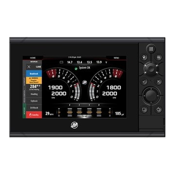
VesselView 703 multifunction display
1
Sealing gasket
8
Mounting screws
1
Mounting screw alignment tool
1
NMEA® 2000 T‑connector
1
VesselView Link harness
1
NMEA® 2000 extension harness
2
Bezel trim
1
Sun cover
Cutting the Instrument Panel
Preparing the Mounting Location
1.
Select a suitable location for the VesselView on the boat's instrument panel.
NOTE: The area behind the panel should be clear of any cables, wiring, or other hardware that may interfere with
installation. The mounting location should also provide good visibility from the boat operator's position.
2.
Disconnect the batteries powering the gauges or SmartCraft components.
3.
Cut out the supplied template.
NOTE: Always check the template cutout to the mounting holes on the VesselView before drilling.
4.
Use the template to determine the space required for mounting.
5.
Prepare the mounting location surface as follows:
•
Fiberglass panels: Apply masking tape to the area being cut to prevent cracking the fiberglass.
90-8M0124492 eng MARCH 2017
Description
© 2017 Mercury Marine
62983
Page 1 / 6
Advertisement
Table of Contents

Summary of Contents for Mercury VESSELVIEW 703
- Page 1 Mercury Marine products, have the work performed by an authorized Mercury Marine dealer technician. Improper installation or servicing of the Mercury product could result in damage to the product or personal injury to those installing or operating the product. Always refer to the appropriate Mercury Marine manual for component removal and installation instructions.
- Page 2 Remove the template and insert the VesselView into the panel to ensure fit. Do not secure to the instrument panel at this time. Securing VesselView to the Instrument Panel Mounting screws Mounting screw alignment tool VesselView Helm panel 62985 Insert the VesselView into the opening. Page 2 / 6 © 2017 Mercury Marine 90-8M0124492 eng MARCH 2017...
- Page 3 DTS system. • Never attempt to connect, network, tie into, switch, sink source voltage or current from the DTS wiring harnesses. 90-8M0124492 eng MARCH 2017 © 2017 Mercury Marine Page 3 / 6...
- Page 4 25.4 cm (10 in.) of any connection in a DTS system. • Ensure that all connections are tight. Seal all unused connectors with weather caps. Page 4 / 6 © 2017 Mercury Marine 90-8M0124492 eng MARCH 2017...
- Page 5 VesselView 703 Connections IMPORTANT: When replacing a VesselView 702 with a VesselView 703, it is important to know that the 703 has built‑in sonar and wifi capabilities. If you are upgrading to VesselView 703 from a VesselView 702 display that used an external WIFI‑1 module and/or an external sonar module, it is recommended to use the capability of the 703 and no longer use the external modules.
- Page 6 VESSELVIEW 703 Products of Mercury Marine © MERCURY MARINE. All rights reserved. Reproduction in whole or in part without permission is prohibited. Alpha, Axius, Bravo One, Bravo Two, Bravo Three, Circle M with Waves Logo, K-planes, Mariner, MerCathode, W6250 Pioneer Road...


Need help?
Do you have a question about the VESSELVIEW 703 and is the answer not in the manual?
Questions and answers