
Related Manuals for ABB PrimeGear ZX0


Summary of Contents for ABB PrimeGear ZX0
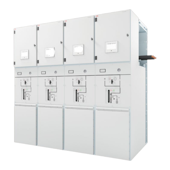
- Page 1 — PRODUCT MANUAL PrimeGear ZX0 Gas-insulated medium voltage switchgear • Greener • Smarter • Safer • More reliable...
-
Page 3: Table Of Contents
— Table of contents Your safety first - always! Standards, regulations, notes, further documents 1. Dispatch and storage 2. Installation of the switchgear at site 3. Commissioning 4. Operation 5. Test procedures 6. Service 7. Actions at the end of the service life 8. -
Page 4: Your Safety First - Always
The sequence of safety rules personnel or managed and supervised by the therefore deviates from that proposed in the ABB Service Department. standard as follows. • Ensure that installation, operation and maintenance are only performed by specialist Isolate, electricians familiar with this manual. -
Page 5: Standards, Regulations, Notes, Further Documents
S T A N D A R D S , R E G U L A T I O N S , N O T E S , F U R T H E R D O C U M E N T S —... - Page 6 Operator safety in accordance with IEC 62271-200 • Front view. | GB 3906 assumes that the conditions stipulated • Construction data if compiled specifically for by ABB are complied with (see also Technical this order. Catalogue TK 1YHA000299). • Circuit diagrams.
- Page 7 S T A N D A R D S , R E G U L A T I O N S , N O T E S , F U R T H E R D O C U M E N T S In order to prevent accidents (particularly Wear appropriate work clothes and injury to hands!) extreme care should be...
-
Page 8: Dispatch And Storage
When airfreighted, however, the panels are delivered with reduced pressure. Take account of the weight of the transport • If airfreight with PrimeGear ZX0 panels is needed, units when selecting the handling please contact ABB for further guidance. equipment. - Page 9 The ABB scope of supply does not include suspension ropes and shackles. — Fig. 1.4.2.1: Preparing a...
- Page 10 PrimeGe ar Z X0 P R O D U C T M A N U A L 1.4.3 Handling by hydraulic lift trolley 1.5 Intermediate storage When moving panels of 450 mm width, • Store the panels in the upright position. fit the lateral support plates supplied as •...
-
Page 11: Installation Of The Switchgear At Site
• If there is a concrete floor a foundation frame is tightening torques apply to unlubricated screw required. Standard foundation frames supplied connections. by ABB must be embedded in the floor topping. • In addition to a standard foundation frame for Please consult the manufacturer’s... - Page 12 • Evenness tolerance: ± 1 mm/m. If no standard ABB foundation frames are used, • Straightness tolerance: max. 1 mm/m, but max. observe the relevant construction and laying 2 mm for the entire length.
- Page 13 I N S T A L L A T I O N O F T H E S W I T C H G E A R A T S I T E 2.2.1 Installation of standard foundation frames • Fasten the brackets (2) of the foundation frame Standard foundation frames are delivered to site to the floor, using one knock-in anchor (5) and completely preassembled.
- Page 14 PrimeGe ar Z X0 P R O D U C T M A N U A L — Fig. 2.2.1.2: Installation of the floor frame Rear front Section A-A Top of finished floor Floor topping *: Only in the case of reinforced foundation frames. —...
- Page 15 The reading must be in the green area of mechanism bay behind the operator controls on the instrument’s scale. If it is not, or if the panel. the site altitude is above 1000 m, please contact ABB. — Fig.2.3.1 location of gas density manometer —...
- Page 16 Fitting the stud bolts for the solid-insulated When a standard foundation frame supplied by busbars ABB is used, remove the protective film. Grease • The stud bolts are part of the busbar supply. the top surfaces of the foundation frame or Use original stud bolts only.
- Page 17 I N S T A L L A T I O N O F T H E S W I T C H G E A R A T S I T E 2.3.2 Erection of the panels washer 8.5 x 30 x 3 and 1 x dished washer 8) and •...
- Page 18 P rimeGe ar Z X0 P R O D U C T M A N U A L — Fig. 2.3.2.2: Fastening the panel to the conventional foundation frame Remove the pressure relief plate from rear side of panel Fasten from here to the floor frame —...
- Page 19 I N S T A L L A T I O N O F T H E S W I T C H G E A R A T S I T E — Fastening of the panels when using the reinforced Fig.
- Page 20 P rimeGe ar Z X0 P R O D U C T M A N U A L • Carefully slide the panel to be installed up to the • In Fig.2.3.2.4, point 1 and 2 are for panel panel which is already in place. connection;...
- Page 21 I N S T A L L A T I O N O F T H E S W I T C H G E A R A T S I T E — Fig. 2.3.2.5: Distance L to be measured between the cast resin busbar bushings of adjacent panels...
- Page 22 PrimeGe ar Z X0 P R O D U C T M A N U A L • Install the further panels in the manner described. • Connect the earthing bars of the panels together • Guide the control cables for the panel to panel (Fig.2.3.2.6) by dismantling the earthing link connections through the opening in the low fitted at the works for transport, guiding it...
- Page 23 ABB Service Department. after this has been agreed with ABB Cleaning the cast resin bushings Service Department. • Remove surplus or dirty grease from the silicone The silicone surface must be free of part with a soft, clean, non-fraying cloth.
- Page 24 PrimeGe ar Z X0 P R O D U C T M A N U A L 2.3.4.2 Assembling the busbar 2.3.4.3 Earthing the busbar The stud bolts (8) have been fitted as described in The busbar adapters are to be earthed at the section 2.3.1.3.
- Page 25 I N S T A L L A T I O N O F T H E S W I T C H G E A R A T S I T E — Fit the clamps and connect the earthing leads to Fig.
- Page 26 Top bushing with capacitive indicator for busbar at the rear of the low voltage compartment. is available as option in PrimeGear ZX0. The length of the cable is relevant to the function of the indicator. The cable must therefore not be shortened or lengthened or otherwise modified.
- Page 27 I N S T A L L A T I O N O F T H E S W I T C H G E A R A T S I T E Connect the earthing conductor of the cable to the Check the function of the capacitive clamping nut on top busbar bushing pressplate indicator, for instance in the course of...
- Page 28 P rimeGe ar Z X0 P R O D U C T M A N U A L 2.3.4.5 Installation of busbar current transformer The same type of 1250A current transformer support is compatible for all different width panels. Due to the weight of busbar current transformer, during the assembly, a lifting device is recommended.
- Page 29 I N S T A L L A T I O N O F T H E S W I T C H G E A R A T S I T E Step 3 Step 4 Screw the phase support of three phases with •...
- Page 30 P rimeGe ar Z X0 P R O D U C T M A N U A L — Fig. 2.3.4.5.5 Installing the further current transformers — Fig. 2.3.7.1 Fitting the cover plates — Fig. 2.3.4.5.5 • Follow the same procedure to install the further transformers.
- Page 31 I N S T A L L A T I O N O F T H E S W I T C H G E A R A T S I T E 2.3.4.6 Installation of the busbar and current •...
- Page 32 P rimeGe ar Z X0 P R O D U C T M A N U A L • Start installation with the rear bar. outside the panels. • Fit the two bushings concerned with stud bolts • In the further course of installation, observe the as described in section 2.3.1.3 (see Fig.
- Page 33 I N S T A L L A T I O N O F T H E S W I T C H G E A R A T S I T E • Move the preassembled unit into the termination instruction).
- Page 34 P rimeGe ar Z X0 P R O D U C T M A N U A L • Install the further busbars in the manner described above. • Refit the main earthing bar and the connections between the main earthing bar and the adjacent panels.
- Page 35 I N S T A L L A T I O N O F T H E S W I T C H G E A R A T S I T E — 2.3.4.7 Installation of the busbar voltage Position A is the bores for width 600 mm panel.
- Page 36 PrimeGe ar Z X0 P R O D U C T M A N U A L Step 3 Screw the landing plate on the top of tank with 6 welded studs as shown in Fig. 2.3.4.7.3. 6 x Nut, M8 6 x Dished washer, 8 Landing plate —...
- Page 37 Apply only moderate pressure when only use the component after this has cleaning the silicone surfaces. been agreed with ABB Service • After cleaning with intensive cleaner M.X.T. 60 Department. forte, wipe the silicone surtace with a dry cloth.
- Page 38 PrimeGe ar Z X0 P R O D U C T M A N U A L Connect the plugs on the instrument transformer secondary wiring with the connectors on the transformers as shown in the circuit diagram. — Fig. 2.3.4.7.6 Three-phase voltage transformer set installed of 500 mm...
- Page 39 I N S T A L L A T I O N O F T H E S W I T C H G E A R A T S I T E 2.3.4.8 Installation of busbar current sensors • After the assembly of all sensors has been Observe the correction factors on the name plate completed, route the sensor cables to the low of the sensors before mounting.
- Page 40 • Pull out the cable tie and turn the voltage sensor agreed with ABB Service Department. approximately 1.5 turns counterclockwise. • Tighten the voltage sensor to 30 Nm.
- Page 41 I N S T A L L A T I O N O F T H E S W I T C H G E A R A T S I T E — Fig. 2.3.4.9.1 Mounting the voltage sensor —...
- Page 42 (Fig. 2.3.5.1) are supplied fitted and ready for operation. In individual cases, voltage transformers may also be supplied loose. Please contact ABB for installation information. If the transformers are fitted with a terminal board, wire the transformers after installation according to chapter 2.3.5.1.
- Page 43 I N S T A L L A T I O N O F T H E S W I T C H G E A R A T S I T E — 2.3.5.1 Wiring of the voltage transformers Fig.
- Page 44 P rimeGe ar Z X0 P R O D U C T M A N U A L Earthing of open delta windings Remove the earthing wire of the open delta If the open delta windings of the voltage windings from the terminal boards of the transformers are damped with a resistor, the voltage transformers in accordance with windings connected in an open delta are to be...
- Page 45 Details of the cross section and the number of connections can be found in Attach the damping resistor according to the the earthing diagram (not included in supplied assembly drawings. ABB’s scope of supply). Resistor — Fig. 2.3.6.1 Position of damping resistors...
- Page 46 Checking the outer cones • Check that the switchgear room is in proper Check the outer cones for damage. If condition for operation and establish that there is damage to the outer cones, please condition if necessary. contact ABB Service Department.
-
Page 47: Commissioning
C O M M I S S I O N I N G — 3. Commissioning 3.1 Conditions for commissioning of the switchgear decomposed 3M™ Novec™ 5110 (an example The conditions for commissioning of the can be found in instruction manual switchgear are as follows: 1YHA000300 en) is displayed in the •... -
Page 48: Operation
P rimeGe ar Z X0 P R O D U C T M A N U A L — 4. Operation General notes • The three position disconnector (disconnector • All activities in connection with operation of the and earthing switch function) can only be switchgear require compliance with EN 50110 operated when the circuit breaker is open. - Page 49 O P E R A T I O N — Earth feeder Connect feeder Fig. 4.1.1 Earthing a feeder and cancelling the earthing — Fig. 4.1.2 Connecting and disconnecting a Feeder Earthing Feeder Feeder Connection Feeder feeder panel disconnected prepared earthed disconnected prepared...
- Page 50 PrimeGe ar Z X0 P R O D U C T M A N U A L — Fig. 4.1.5 Opening the disconnector and switch-disconnector s in the feeder panels in the area of the busbar section to be earthed —...
- Page 51 O P E R A T I O N 4.1.2 Operation of the circuit breaker Note on “securing to prevent cancellation of Depending on the version of the switchgear earthing” interlock system, the circuit breaker can be operated remotely (from the control room) or locally. At the The interlock has two different bores for panel, the circuit breaker operating mechanism can U-locks.
- Page 52 PrimeGe ar Z X0 P R O D U C T M A N U A L 4.1.2.1 Manual operation of the circuit breaker • Cancel any blocking of the relevant pushbutton • Mechanical switch position indication is by removing the padlock or by releasing a lock effected by graphical symbols (3 in Fig.
- Page 53 -RLE1 blocks the ON button) mechanism, and may only be performed by qualified and a charged spring mechanism. The state of the personnel. Contact the ABB Service Department if spring mechanism is indicated mechanically (Fig. necessary. 4.1.2.2.1).
- Page 54 PrimeGe ar Z X0 P R O D U C T M A N U A L 4.1.3 Operation of the three position • The selector lever can be blocked by a padlock. disconnector To fit the padlock, press the selector lever Depending on the version of the switchgear towards the cover.
- Page 55 O P E R A T I O N Operation of the disconnector Operation of the earthing switch • Turn the selector lever (4 in Fig. 4.1.2.1.3) • Turn the selector lever (4 in Fig. 4.1.3.1.3) counterclockwise and hold it fast. clockwise and hold it fast.
- Page 56 In such a case, unit and mechanically on the operating mechanisms. please contact the ABB Service Department. Manual operation 4.3 Gas monitoring with gas density manometer Operation of the disconnector The high-voltage compartments must have •...
- Page 57 O P E R A T I O N transformer isolating device is located in the cable The controls and indicators for the voltage termination compartment on the righthand side transformer isolating device are shown in Fig.4.4.2. wall (Fig.4.4.1). Check the switch position indicator (5 and 6). The isolating device can be secured with a padlock (3).
- Page 58 P rimeGe ar Z X0 P R O D U C T M A N U A L Isolating and earthing the voltage transformers Connecting the voltage transformers or voltage or voltage sensors sensors To isolate and earth the voltage transformers or To connect the voltage transformers or voltage voltage sensors, slide the locking plate (1) upwards sensors, slide the locking plate (1) upwards and...
-
Page 59: Test Procedures
T E S T P R O C E D U R E S — 5. Test procedures 5.1 Testing for the off-circuit condition 5.1.1 LRM-system The off-circuit condition on the cable side is tested Testing for the off-circuit condition is performed by means of the capacitive voltage indicator (pick- with a plug-in display unit (design to IEC 61243-5) off on the outer cone). - Page 60 P rimeGe ar Z X0 P R O D U C T M A N U A L 5.2 Testing for the in-phase condition • Establish the test circuit in accordance with the Testing for the in-phase condition, e.g. when manufacturer’s directions for the test apparatus.
- Page 61 T E S T P R O C E D U R E S If there are isolatable voltage transformers 5.4 Secondary protection testing or sockets for these within the section of Comply with the safety regulations to EN the system to be tested, use the isolating 50110.
- Page 62 P rimeGe ar Z X0 P R O D U C T M A N U A L Note that when the voltage signals from 5.5 Protection testing by primary current the voltage transformers or voltage injection sensors in the panel to be tested are Direct access to the conductors for performance used by other panels, the signals are not of protection tests by primary current injection is...
- Page 63 T E S T P R O C E D U R E S If the circuit breaker is also to be tested, • Dismantle the cover on the cable termination please note that earthing via the circuit compartment of the relevant panel. breaker is cancelled when the breaker is •...
-
Page 64: Service
PrimeGe ar Z X0 P R O D U C T M A N U A L — 6. Service 6.1 Inspection and maintenance of the 6.2 Maintenance of the switching devices and switchgear their operating mechanisms • Check that the switchgear room and the Please consult the relevant directions and switchgear are in proper condition for the instruction manuals for the actions and intervals... -
Page 65: Actions At The End Of The Service Life
A C T I O N S A T T H E E N D O F T H E S E R V I C E L I F E — 7. Actions at the end of the service life ABB can be appointed to decommission and Further notes on decommissioning at the end of dismantle the switchgear. The switchgear is then the switch-gear’s service life can be found in... -
Page 66: Overview Of The Busbar Parts And Assemblies
Table 8.2.1: Busbars for a busbar current of up to 1250 A Rated voltage (kV) Designition Widths of the panels to be Quantity ABB part number connected (mm) BB 1250 A 450-450 L=432 Ur<=12 kV P125 450-450 2RJA026404A0001 BB 1250 A 450-500 L=457 Ur<=12 kV P125... - Page 67 Table 8.1.2: End and cross adapter assemblies for a busbar current of up to 1250 A Rated voltage (kV) Designation Quantity ABB part number Across Adapter 1250 A Ur<=12 kV P125 2RJA026392A0001 12 kV Across Adapter 1250 End Ur<=12 kV P125 2RJA026394A0001 Across Adapter ...
-
Page 68: List Of Tools
The tools required for assembly of the switchgear 1 Guide string system are detailed in the list below. Tools are not 1 Scribing iron part of the ABB scope of supply. 1 Punch 1 Tri-square All the tools listed must comply with the safety 1 Tape measure regulations of the country concerned. -
Page 69: Working Materials, Auxiliary Materials And Accessories
As a rule, the panel modules are filled with insulating gas at the works. For this reason, no gas cylinders are supplied with the switchgear. Gas cylinders are not normally part of the ABB scope of supply. If airfreight with PrimeGear ZX0 panels is needed, please contact ABB for further guidance. -
Page 70: Technical Data
P ri m e G e ar Z X 0 P R O D U C T M A N U A L — 11. Technical data The technical data of the switchgear can be found the opened low voltage compartment. Further on the name plate. - Page 71 T E C H N I C A L D A T A Rated voltage 12 kV 24 kV Insulating gas DryAir /SF AirPlus/SF Degree of protection for gas filled panel modules IP65 Degree of protection of low voltage compartment and the mechanism bay IP3X Ambient air temperature, maximum °C...
- Page 72 P ri m e G e ar Z X 0 P R O D U C T M A N U A L — Fig.11.1 Feeder panel, 630 A, example configuration — Fig.11.2 Feeder panel, 1250 A, example configuration — Fig.11.3 Feeder panel, 1.12 1250 A, example (With...
- Page 73 M E M O — MEMO...
- Page 74 ABB Connect The digital assistant for all your electrification needs ABB Connect helps you to find product information and stay connected to the latest news and tools. It’s a digital assistant that enables customers to connect to the broadest range of electrification solutions in one place.
- Page 75 T E C H N I C A L D A T A...
- Page 76 ABB Xiamen Switchgear Co., Ltd. No.885, FangShanXiEr Road, Xiang'an District, Xiamen, Fujian, 361101 Tel: 0592 602 6033 Fax: 0592 603 0505 ABB China Customer Service Hot Line TEL: 800-820-9696 / 400-820-9696 mail: cn-ep-hotline@abb.com www.abb.com All rights reserved. Specifications subject to change without notice.