Table of Contents
Advertisement
Advertisement
Table of Contents
Troubleshooting

Related Manuals for Kioti WD1260

Summary of Contents for Kioti WD1260
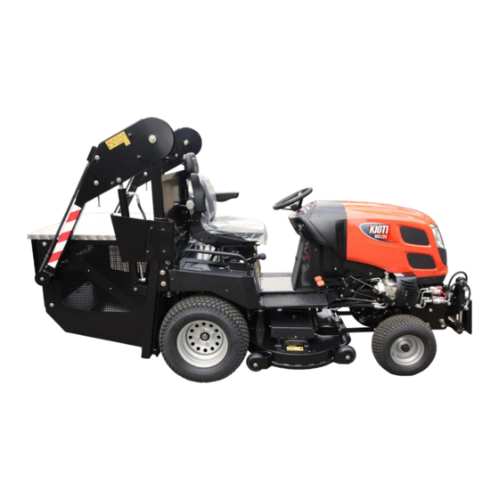
- Page 1 WD1260 Operator’s Manual Hazard control and accident prevention are dependent upon the awareness, concern, prudence, and proper training of personnel involved in the operation, transport, maintenance, and storage of equipment. Document Version: March 2015...
-
Page 2: Parking Safely
Attention!! The above SAFETY ALERT SYMBOL is used throughout this manual to bring attention to important safety instructions. For your safety and the safety of others, these instructions must be followed or SERIOUS ATTENTION! INJURY OR DEATH MAY RESULT. BECOME ALERT! YOUR SAFETY IS INVOLVED! OBEY THIS MESSAGE! PARKING SAFELY... -
Page 3: Table Of Contents
Table of Contents PARKING SAFELY ............. 2 CONTROLS............21 SAFETY DECALS ............2 ... 21 VERVIEW OF OMPONENTS AND ONTROLS INTRODUCTION ..........5 DESCRIPTION OF CONTROLS ......22 ............ 5 ............22 ONGRATULATIONS ANEL ......5 ............22 SING PERATOR ANUAL RIVE EDALS... - Page 4 ........35 ..............42 NGINE AINTENANCE HART ELTS ..........35 ........42 NGINE UBRICANTS OWING IMING ....... 35 ..........42 OWING AINTENANCE HART ENSION AUGE ..36 ........42 HUTE AND OLLECTOR AINTENANCE HART OWING RIVE ..........36 ........43 ONTAINER EMOVING OWING...
-
Page 5: Introduction
1. INTRODUCTION described within this manual may be optional. Some ONGRATULATIONS illustrations and descriptions may not be applicable to Thank You for purchasing a Wisconsin Engineering your unit. All data given in this book is subject to Product. You have purchased one of the finest, most production variations, and were in effect at the time of advanced lawn tractors available. -
Page 6: Warranty And Service Information
of machine damage, and helpful operating and servicing information. Please read all the highlighted WARNING: Engine exhaust, some of it’s information carefully to avoid injury and damage to the machine. constituents, and certain vehicle components contain or emit chemicals known to the State of California to cause cancer and birth defects or other reproductive harm. -
Page 7: International Control Symbols
3. INTERNATIONAL CONTROL SYMBOLS As a guide to the operation of your tractor, various international symbols have been utilized in the instruments, controls, and safety decals. The symbols are shown below with their meaning. Not all symbols may be used on your machine! Read Total Recorded... -
Page 8: International Safety Symbols
4. INTERNATIONAL SAFETY SYMBOLS Always refer to Attachment’s Operator Manual for safe The following symbols are international standards for warnings of operating dangers. Some may operating instructions appear on your tractor or equipment. THE LIST IS NOT COMPLETE AND DOES NOT ADDRESS This information is for reference only. -
Page 9: Safety
5. SAFETY & S IGNAL ORDS AFETY LERTS OTATIONS NOTE: General reference and helpful information for proper operation and maintenance practices. IMPORTANT: Specific procedures or information required to prevent damage to the machine or an attachment. QUIPMENT AFETY UIDELINES ATTENTION! BECOME ALERT! Safe operation is a major concern when operating any YOUR SAFETY IS INVOLVED! -
Page 10: Learn Safe Practices And Operator Training I Sr
To provide a better view, some photographs and SSEMBLY AFETY illustrations show the mower without certain safety Read, understand, and follow all safety practices in shields. This is done for illustrative purposes only – this manual before beginning assembly. Failure to the machine should never be operated in this follow instructions could result in personal injury and/or condition. -
Page 11: Passengers
• Braking and steering characteristics Keep children out of work area and under watchful care of a responsible adult. Always be on the lookout • Turning radius and clearances for small children or their toys. Be alert and shut off unit if children enter area. -
Page 12: Slope Operation
ALWAYS disengage attachment, stop unit and engine, DO NOT run over any foreign objects which the blades remove key and allow moving parts to stop before may strike or pick up and throw. opening or removing the grass collector. As grass catcher fills, be alert to changing unit stability ALWAYS disengage attachment, stop unit and engine, and control. -
Page 13: Prevent Fires
flames away from the battery and fuel tank. The the manufacturer. Tires should always be kept battery presents an explosive hazard because it vents inflated to the recommended pressure. Cracked, cut, off hydrogen and oxygen gas, especially when worn, or otherwise damaged tires should be replaced recharging. -
Page 14: High Pressure Fluid Safety
Remove equipment from trailer or truck bed before Hydraulic hoses and lines can fail due to abrasion, filling. damage, kinks, age, and exposure. Check hoses and lines regularly. Replace damaged hoses and lines Do not drive equipment near open flames. before operating tractor. -
Page 15: Unpacking And Preparation
6. UNPACKING AND PREPARATION Read and understand operator’s manual contents prior DJUST IGURE to unpacking, assembling, or operating equipment. For transportation reasons, the mower is often shipped partially disassembled. Visually inspect the machine for damage, loose nuts or bolts, and take note of the safety signs and their messages. - Page 16 Install the High Dump System Caution! For the central hose holder only partially Pick up the Collector with loosen the bolt and turn it a hoist or forklift. to place the hoses in the holder. When the hoses are in Carefully position the place turn the holder to its collector on the back of the...
-
Page 17: Install Dispersion Hood
WEIGHT The Front Counter-weight must be installed at all times Connect the wires to the when operating the WD1260 with High Dump System Interlock Switch. on uneven terrain or slopes. The Front Counter-weight is not required if using the normal collector. -
Page 18: Engine Oil
NGINE NFLATION 1.4 bar FRONT (20 psi) 1.0 bar REAR (15 psi) Figure 6-8 Proper tire inflation is important for an even cut and maintaining lawn mower balance. Check pressure using a low pressure tire gauge. Over inflated tires may burst. Never operate the mower with flat tire(s). Under inflated tires can fall off of the wheel during Figure 6-6 operation, leading to tire damage and dangerous loss... -
Page 19: Anti -Scalping Casters
PTIONAL QUIPMENT CALPING ASTERS See Operating Section for more information regarding the optional equipment that may be installed on your WARNING! AVOID INJURY! DO NOT machine. ATTEMPT TO ADJUST THE CASTERS OR ANY PART OF THE EQUIPMENT WHILE THE BLADES ARE MOVING. Make sure the engine if off and the blades have stopped HECK AFETY... -
Page 20: Safety Interlock System
7. SAFETY INTERLOCK SYSTEM WARNING! Never tamper with the safety interlock system. It is designed to protect you and those around you from an accident. Tampering with safety components may render your machine unsuitable for safe operation, and will void warranty. The mower is equipped with a Safety Interlock System (SIS). -
Page 21: Controls
8. CONTROLS Right side view Left side view Figure 8-1: Main Components and Controls VERVIEW OF OMPONENTS AND ONTROLS Mowing Deck 11) Ignition High Lift Collector 12) Dash Panel (see Figure 9-1) Front Hitch (optional) 13) Differential Lock control switch Front Counter-weight (optional) 14) Lever for chute cleaning Operator Seat... -
Page 22: Description Of Controls
9. DESCRIPTION OF CONTROLS RIVE EDALS ANEL 11 12 13 Figure 9-2 Figure 9-1 Dash Panel Dash Panel 1) Switch for snow blower tunnel angle (optional) 2) Switch for snow blower tunnel rotation (optional) 3) Steering wheel bolt cover 4) Light switch 5) Switch for Auto/Man full collector mode 6) Switch for engaging mowing deck •... -
Page 23: Brake Pedal And Parking
To disengage the parking brake, depress the brake pedal fully. The engagement lever springs back automatically. OWING EIGHT DJUSTMENT Figure 9-3 Disengaging the Hydrostatic Drive The manual bypass valve (#1 In Figure 9-3) allows moving the tractor for short distances at low speeds without operating the engine. -
Page 24: Ignition Switch
GNITION WITCH HUTOFF YSTEM Overview Wisconsin Engineering’s patented A UTOMATIC virtually eliminates clogging. It HUTOFF YSTEM is perhaps the most advanced system of it’s type available. By precisely monitoring flow through the discharge chute, the Wisconsin Engineering Full Bag System is not adversely affected by variations in grass weight or terrain conditions The system has two settings: Figure 9-6... - Page 25 Using the Full Bag Detection System With the AUTO/MAN in the AUTO position, the full- bag detection system is activated. Once PTO is turned on, the blades will be engaged until either: the operator disengages them using the PTO ENGAGEMENT SWITCH, the container is full.
-
Page 26: Operating
OPERATING (#3 In Figure 9-6) to start the engine. When the engine is on, the key returns automatically to ILLING FUEL position “engine running” (#2 In Figure 9-6). To add fuel to Fuel Tank: 4. Release the brake pedal. To release the parking brake, step on and release the brake pedal. -
Page 27: W I E
ARMING AND DLING THE NGINE CAUTION! Avoid Injury! Come to a full To warm or idle engine, LOCK the park brake and: stop before changing forward/reverse Warming Engine: Set hand throttle lever to the 1/2 direction. Machine damage or loss of control fast position for 3 to 4 minutes without load. -
Page 28: Standard Grass Collector
installed or electrical system damage will result. YSTEM PERATION TANDARD RASS OLLECTOR PERATION Check the fullness of the grass container frequently while mowing if not cutting in the automatic mode. DANGER! Avoid Injury and Damage. Make sure the container does not become overfilled For safe operation of the High Dump during operation, or the discharge chute may clog. -
Page 29: High Dump Systemc
YSTEM OMPONENTS Figure 10-4 Rear Baffle Interlock Switch Right Frame Arm Right Lifting Arm Collector Left Panel Hydraulic Cylinder Return Valve Hydraulic distributor... -
Page 30: Rear Panel Interlocks
To Empty the High Dump System Collector: ANEL NTERLOCK WITCH The PTO clutch will not engage if the Interlock Switch on the rear panel is not depressed. Never attempt to bypass this switch electrically or mechanically. Use only attachments approved by Wisconsin Engineering. Keep the switch covers free of debris. -
Page 31: Optional Equipment
PTIONAL QUIPMENT OWING INTS Lawn tractor must be parked safely before the Mow in longitudinal and cross directions and slightly following equipment is installed. overlapping previous cuts. This gives a better quality cut and better final appearance. Bumper When mowing tall grass or vacuuming debris, slower speeds generally provide better results. -
Page 32: 11. Lawn Tractor Accessories
useful for reducing bulky leaves into a finer size for 11. LAWN TRACTOR ACCESSORIES collection. heavy duty bumper for increased RONT UMPER A sturdy, practical trailer with TILITY RAILER protection, and facilitated manipulation independently removable sides for outstanding versatility Rugged, all-season front mount WEEPING RUSH sweeping brush removes leaves, trash, and light snow... -
Page 33: Cleaning And Storing
CLEANING AND STORING Properly clean the mower after each operation. A regular 2. Wash surface of tractor with low (hose) water maintenance schedule is mandatory for safety, and a few pressure and a mild detergent. extra minutes spent cleaning and maintaining your 3. -
Page 34: Maintenance, Service, And Adjustments
MAINTENANCE, SERVICE, AND ADJUSTMENTS This manual contains information regarding safe handling and proper maintenance procedures. For information not contained within this manual, it is necessary to contact an authorized dealer or service center. WARNING: AVOID INJURY. Read and understand Maintenance and Service and Battery Safety Rules in Safety section before attempting any maintenance. -
Page 35: Engine Maintenance Chart
** Replace only if necessary. The items listed above (# marked) are registered as emission related critical parts by KIOTI in U.S. EPA exhaust emission standard non-road emission regulation. As the engine owner, you are responsible for the performance of the required maintenance on the above instruction. -
Page 36: Chute And Collectorm
HUTE AND OLLECTOR AINTENANCE HART After the first Every Every After every After every After each Maintenance Operation machine 5 working week month 50 working 100 working season hours hours hours • • • • • • - lubrication of grass container and actuator rotating points - inspection of the grass... -
Page 37: Lubrication Point On Spindle
& T UBRICATION OINT ON PINDLE EARINGS DENTIFICATION ECHNICAL ERVICE Each lawn mower is delivered with a manufacturer’s label which indicates model, serial number, and year of production. These numbers are necessary when ordering parts or contacting an authorized dealer for service or parts. -
Page 38: Checking Belts Tension
After the first 5 hours of use, tighten bolt (#1) on front YDRAULIC ILTER axle (#2). Check Front Axle lubrication point monthly or every 50 hours. Lubricate as required. HECKING ELTS ENSION Belts must be kept clean and tensioned correctly at all times. -
Page 39: Checking Engine Oil
into the oil pan. All the used oil can be drained out easily when the engine is still warm. HECKING NGINE 4. Remove engine oil filler cap to allow easy draining of engine oil. Figure 13-8 Figure 13-10 1. Check engine oil daily. 5. - Page 40 IMPORTANT! Use only KIOTI genuine engine oil and DJUSTING ENSION filters to insure smooth operation and durability of the In order to extend the fan belt’s lifetime, the tension of engine. the belt should be correctly adjusted if it slips. The belt tension should be inspected regularly according to the following procedure.
-
Page 41: Tires And Wheels
(#3) is heading downward. 1.0 bar CAUTION! REAR • Use only a genuine KIOTI filter. Use of a non- (15 psi) recommended filter can cause damage to the engine and sensor. • Make sure that no dust enters the system by installing the cover firmly. -
Page 42: Mowing Deck Maintenance
MOWING DECK MAINTENANCE ISCHARGE HUTE The discharge chute must be kept clean and free of debris. If the discharge chute needs to be removed, all electrical connections to the chute must be disconnected before completely removing the chute. ETECTOR The Full Bag Sensor diaphragm on the inside of the discharge chute must be kept free of accumulated grass and debris. - Page 43 EMOVING OWING Figure 14-5 1. Park the mower over a clean and level work surface. 2. Check and adjust tire pressure. Figure 14-3 3. Place deck in lowest position. 4. Loosen the front linkage bolts on the left and right deck support linkages.
-
Page 44: Removing Mowing Deck
Installation of the flop holder For operating the machine without the mowing deck, it is important to install the flop holder. Figure 14-6 5. Lift deck to highest position and make sure the deck cover does not contact the drive belt (minimum of 6 mm clearance.) 6. - Page 45 Mowing Blade Removal Use gloves whenever handling blades as sharp edges can cut fingers. Figure 14-12 1. Clamp a screwdriver or thin rod horizontally into a vice. 2. Rest the blade on the center mounting hole on the screwdriver/rod parallel to the ground. 3.
-
Page 46: High Dump System Maintenance
HIGH DUMP SYSTEM MAINTENANCE HAIN AINTENANCE Figure 15-1 Adjusting Chain Tension: Use the chain tensioning mechanism (Figure 15-1) to correctly tension the lifting chain. Correct lifting chain tension: The chain must not have any slack or free play. The chain must be tightened so that under moderate finger pressure it is possible to push the chain against the collector lift arm. -
Page 47: Electrical System
ELECTRICAL SYSTEM EPLACEMENT ATTERY Do not apply excessive pressure to bulbs as they may WARNING: AVOID INJURY. Read and break and cause injury! Replace defective bulbs only understand Battery Safety Rules in with identical bulbs. Safety section before attempting any battery maintenance. -
Page 48: Specifications
SPECIFICATIONS WD1260 Engine Manufacturer SHIBAURA Power (hp) 26 HP Alternator 12V/40A Deck Width 1220 mm Blades Rotation Counter-rotating Cut Height 20-120 mm Electromagnetic clutch with brake Collection Central deck ejection to rear mounted collector Collector Normal Collector High Tip Collector... -
Page 49: Troubleshooting Guide
TROUBLESHOOTING GUIDE Problem Correction Mower cuts ragged or Mowing very tall or wet grass could adversely affect mowing performance. Adjust deck height to a higher position, uneven reduce mowing speed, and/or let the grass dry. Raise deck height or reduce mowing speed Remove accumulated grass clippings from the underside of the deck Make sure blades are not dull or damaged Make sure all blade attachment bolts are present and tightened appropriately. -
Page 50: Engine Troubleshooting
Temperature Fuel type - Above 14°F (-10°C) NO.2 Diesel - Below 14°F (-10°C) NO.1 Diesel Nozzle is bad If necessary, replace with new nozzle. If you do not find the cause of trouble, consult your KIOTI dealer for assistance. -
Page 51: Bolt Torque Reference
BOLT TORQUE REFERENCE Unless otherwise specified, tighten hardware to the following standards. METRIC Grade 4T Grade 7T Grade 8T Torque Torque Torque Pound Feet Newton meters Pound Feet Newton meters Pound Feet Newton meters 1.00 12.7 13.6 1.25 29.8 27.1 35.2 1.50 27.1... -
Page 52: Accessories And Spare Parts
ACCESSORIES AND SPARE PARTS MODEL Engine Mowing Deck WD1260 Shibaura 48"/122 cm Collector Options (one required) E9658 Standard Collector (640 liter) E9660 High Dump System (600 liter) E1766 Grass Collector Dust deflector E8901 Dispersing Hood Options 7602100 Zinc Dipped Mowing Deck (extra cost above standard deck) - Page 53 Gt2 920 8Mgt 15 091012 Mowing Deck Belt 627103 Blade Attachment Bolts Set of 2 Shear Bolts and Nuts Set of 4 each 037100&111545 Kioti Oil Filter Shibaura Kioti Air Filter Shibaura Kioti Fuel Filter Shibaura 627040 Hydraulic Oil Filter...
Need help?
Do you have a question about the WD1260 and is the answer not in the manual?
Questions and answers