
Related Manuals for Spectris Particle Measuring Systems Airnet II 4-CH


Summary of Contents for Spectris Particle Measuring Systems Airnet II 4-CH
- Page 1 Without measurement there is no control Airnet® II 4-CH Particle Sensors MODELS 201-4, 301-4, 310-4, 501-4, 510-4 OP E RAT I ON S M A N UA L P/N 1000016470...
- Page 2 Airnet® II 4-Channel Particle Sensors (201-4, 301-4, 310-4, 501-4, 510-4) Operations Manual HEADQUARTERS 5475 Airport Blvd BRAZIL JAPAN SINGAPORE Boulder, Colorado 80301 USA T: +55 11 5188 8227 T: +81 3 5298 8175 T: +65 6496 0330 T: +1 303 443 7100, +1 800 238 1801 E: pmsbrazil@pmeasuring.com E: pmsjapan@pmeasuring.com E: pmssingapore@pmeasuring.com...
-
Page 3: Quality Statement
Airnet II 4-Channel Particle Sensors 201-4, 301-4, 310-4, 501-4, 510-4 Operations Manual P/N 1000016470 Rev C © 2021 by Particle Measuring Systems, Inc. All rights reserved. ® Airnet is a registered trademark of Particle Measuring Systems, Inc. ® HyperTerminal is a registered trademark of Hilgraeve, Inc. ®... -
Page 4: Manual Conventions
Manual Conventions WARNING A warning in the text is used to notify the user of the potential for bodily injury or death. CAUTION A caution in the text is used to highlight an item that if not done, or incorrectly done, could damage the instrument and/or any materials or devices affected by the instrument. - Page 5 Declaration of Conformity Application of Council Directive(s): 2014/30/EU, 2014/53/EU, 2014/35/EU, RoHS 2011/65/EU, 2015/ UKCA Electromagnetic Compatibility Regulations 2016, Electrical Equipment (Safety) Regulations 2016 The Restriction of the Use of Certain Hazardous Substances in Electrical and Electronic Equipment Regulations 2012 Standard(s) to which Conformity is Declared: EN 61326-1:2013 S.I.
-
Page 6: Table Of Contents
Table of Contents Quality Statement - - - - - - - - - - - - - - - - - - - - - - - - - - - - - - - - - - - - - - - - - ii Environmental Information - - - - - - - - - - - - - - - - - - - - - - - - - - - - - - - - - ii Patent Information - - - - - - - - - - - - - - - - - - - - - - - - - - - - - - - - - - - - - - - - ii Manual Conventions - - - - - - - - - - - - - - - - - - - - - - - - - - - - - - - - - - - - - - iii... -
Page 7: Table Of Contents
Table of Contents Viewing Configuration Settings - - - - - - - - - - - - - - - - - - - - - - - - - - - - - 3-5 Connecting the Ethernet Cable - - - - - - - - - - - - - - - - - - - - - - - - - - - - - 3-6 Chapter 4: 4-20 mA Signal Configuration / Operation - - - - - - - - - - - - - - - - - - - - - - 4-1 Overview - - - - - - - - - - - - - - - - - - - - - - - - - - - - - - - - - - - - - - - - - - - - - - - - - 4-1 4-20 mA Outputs - - - - - - - - - - - - - - - - - - - - - - - - - - - - - - - - - - - - - - - - - - - 4-1... - Page 8 Table of Contents ADVERTENCIA- - - - - - - - - - - - - - - - - - - - - - - - - - - - - - - - - - - - - - - - - - - - - - C-1 Hazard Symbols - - - - - - - - - - - - - - - - - - - - - - - - - - - - - - - - - - - - - - - - - - - - C-2 Symboles de risque - - - - - - - - - - - - - - - - - - - - - - - - - - - - - - - - - - - - - - - - - C-2 Warnschilder - - - - - - - - - - - - - - - - - - - - - - - - - - - - - - - - - - - - - - - - - - - - - - C-2...
- Page 9 Table of Contents This page is intentionally left blank. viii Airnet® II 4-Channel Particle Sensors Operations Manual...
-
Page 10: List Of Figures
List of Figures Chapter 1: Getting Started - - - - - - - - - - - - - - - - - - - - - - - - - - - - - - - - - - - - - - - - - - - 1-1 Figure 1-1 Airnet II 4-Channel particle sensor - - - - - - - - - - - - - - - - - - - - - - - - - - - - - 1-2 Figure 1-2 Connectors on the back of the Airnet II 4-Channel particle sensor (Shown with 4-20 mA option) - - - - - - - - - - - - - - - - - - - - - - - - - - - - - - - 1-3... - Page 11 List of Figures This page is intentionally left blank. Airnet® II 4-Channel Particle Sensors Operations Manual...
-
Page 12: List Of Tables
List of Tables Chapter 1: Getting Started - - - - - - - - - - - - - - - - - - - - - - - - - - - - - - - - - - - - - - - - - - - 1-1 Table 1-1 Airnet II 4-Channel particle sensor specifications - - - - - - - - - - - - - - - - - - 1-5 Table 1-2 Airnet II 4-Channel particle sensor environmental conditions - - - - - - - - 1-6 Chapter 2: Unpacking and Installation- - - - - - - - - - - - - - - - - - - - - - - - - - - - - - - - - - 2-1... - Page 13 List of Tables Appendix D: - - - - - - - - - - - - - - - - - - - - - - - - - - - - - - - - - - D-1 Airnet®...
-
Page 14: Chapter 1: Getting Started
Chapter 1 Getting Started The Airnet II 4-Channel particle sensor is a laser-optical aerosol particle sensor that accurately detects, counts, and measures particles suspended in air. This manual includes information on operating the following Airnet II 4-Channel models: • 201-4 •... -
Page 15: Class I Laser Product
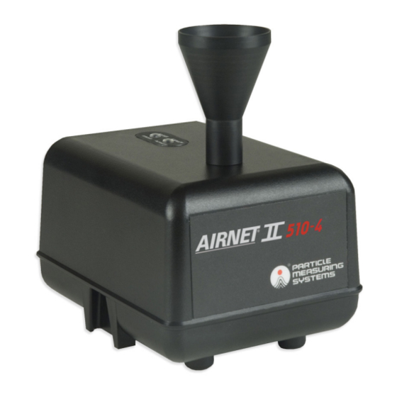
Chapter 1 : Getting Started Class I Laser Product Figure 1-1 Airnet II 4-Channel particle sensor Class I Laser Product The Airnet II 4-Channel particle sensors are Class 1 laser products. WARNING This instrument is a Class l laser product. Use of controls, adjustments, or performance of procedures other than those specified here may result in hazardous radiation exposure. -
Page 16: Physical Description
Physical Description Chapter 1 : Getting Started Physical Description 1. Sample Inlet – 1/4-inch ID Sample probe or tubing 1/4-inch diameter tubing. Two LEDs are located on the top of each Airnet II 4-Channel particle sensor chassis: 2. Status LED – Indicates the operational status of the instrument. When connected to Facility Net software, the LED is controlled by Facility Net’s alarm settings. -
Page 17: Back
Chapter 1 : Getting Started Physical Description Back All connectors are found on the back of the unit’s chassis, including: • Electrical Power – Power can be provided through the 24 VDC power connector (see Figure 2-5, “24 VDC Power Connector,” on page 2-5) when this option board has been purchased, or through the Ethernet connection if Power over Ethernet (PoE) is being utilized. -
Page 18: Specifications
Specifications Chapter 1 : Getting Started Specifications Table 1-1 Airnet II 4-Channel particle sensor specifications 201-4 301-4 310-4 501-4 510-4 Channel thresholds 0.2, 0.3, 0.5, 0.3, 0.5, 1.0, 0.3, 0.5, 1.0, 0.5, 1.0, 5.0, 0.5, 1.0, 5.0, 10.0 10.0 (µm) 0.1 CFM 0.1 CFM 1.0 CFM... -
Page 19: Environmental Conditions
Chapter 1 : Getting Started Environmental Conditions Environmental Conditions The following environmental conditions apply to the Airnet II 4-Channel particle sensor: Table 1-2 Airnet II 4-Channel particle sensor environmental conditions Operating temperatures 4 – 35 °C (39 – 95 °F) Humidity conditions 5 –... -
Page 20: Chapter 2: Unpacking And Installation
Chapter 2 Unpacking and Installation Unpacking 1. Carefully open the container and remove the Airnet II 4-Channel particle sensor. 2. Ensure that all components listed in the following section are included, and inspect each unit for any damage. 3. If any components are damaged, immediately notify the shipper and Particle Measuring Systems. -
Page 21: Items You Need To Provide
Chapter 2 : Unpacking and Installation Items You Need to Provide Items You Need to Provide The following items are not included, and you will need to provide: • Ethernet cable (shielded CAT 5 UTP cable if PoE is used) •... -
Page 22: Selecting A Location
Installation Chapter 2 : Unpacking and Installation If a detector board fails and indicates no counts, this could be similar to not having any particle counts being measured. To address this unlikely but possible failure mode a monitoring algorithm is used to indicate a detector board failure. If a failure occurs it will be indicated within a certain amount of time depending upon the type of instrument being used. -
Page 23: Positioning Or Mounting The Unit
Chapter 2 : Unpacking and Installation Installation • Environmental conditions – The unit should be located in an environment consistent with its temperature, humidity, altitude, and other relevant specifications. • Electromagnetic interference – The unit should be located away from strong electromagnetic fields. -
Page 24: Powering The Sensor From 24 Vdc
Installation Chapter 2 : Unpacking and Installation Powering the Sensor from 24 VDC The Airnet II 4-Channel particle sensor can be powered with sources other than the Power over Ethernet (PoE). The unit may also be powered using a source of 24 VDC power (if this option was ordered) that may be connected to multiple Airnet II 4- Channel particle sensors. -
Page 25: Connecting The Power Supply
Chapter 2 : Unpacking and Installation Installation Connecting the Power Supply After the Airnet II 4-Channel particle sensor has been physically installed with its bracket, connect the sensor to an appropriate power source (PoE or optional 24 VDC). Power over Ethernet requires the use of an internet hub or power injector designed to operate with such systems, as well as the use of a CAT5 shielded cable. -
Page 26: Chapter 3: Configuring For Ethernet
Chapter 3 Configuring for Ethernet Configuration Defined You can configure the Airnet II 4-Channel particle sensor to communicate with Facility Net, send 4-20 mA signals to a SCADA system, or both depending upon the options ordered. Before it can do either, you must configure the sensor. Configuration is the process of making the software and communications settings that will enable the Airnet II 4-Channel particle sensor to communicate with Facility Net or other host program by means of an Ethernet network. -
Page 27: Setting Configuration Addresses For Ethernet
Chapter 3 : Configuring for Ethernet Configuration Defined RS-232 Cable A suitable cable (PMS-CD1995) is provided in your shipment. The wiring for this cable is as follows: Table 3-1 RS-232 pin outs (RJ-11 jack) Pin 1 Transmit Pin 2 Receive ... -
Page 28: Configuration Commands
Configuration Defined Chapter 3 : Configuring for Ethernet Table 3-2 Terminal emulator communications parameters Connector Appropriate to hardware (COM1, for example) When communications are established with the unit, a prompt appears. Enter the Configuration commands (see “Configuration Commands” below) to set the following addresses: 4. -
Page 29: Chapter 3: Configuring For Ethernet
Chapter 3 : Configuring for Ethernet Configuration Defined Set mul(ticast) aaa.bbb.ccc.ddd The multicast address must be set when using Facility Net. This command sets the multicast address in a decimal notation form of aaa.bbb.ccc.ddd. Each three-digit series is a value of 0-255 separated by a period (.) character. This address is unique to the hardware it serves. -
Page 30: Viewing Configuration Settings
Configuration Defined Chapter 3 : Configuring for Ethernet Select the Modbus TCP mode to interface to any third party Modbus TCP client. For additional information, refer to Appendix B, Modbus Protocol Set sam (ple) x y This command sets the minimum sample interval to x seconds and the maximum sample interval (used when zero particles are detected) to y seconds. -
Page 31: Connecting The Ethernet Cable
Chapter 3 : Configuring for Ethernet Configuration Defined Connecting the Ethernet Cable The Airnet II 4-Channel particle sensor communicates with Facility Net software by means of a CAT 5 UTP Ethernet cable. The sensor is designed to work best with a CAT 5 UTP cable. -
Page 32: Overview
Chapter 4 4-20 mA Signal Configuration / Operation Overview The Airnet II 4-Channel particle sensor has an option to be ordered with the ability to transmit five 4-20 mA signals. One signal communicates instrument status and the other four signals transmit particle data from the four particle channels. This data is typically collected and processed by a SCADA system. -
Page 33: Configuring 4-20 Ma Outputs
Chapter 4 : 4-20 mA Signal Configuration / Operation Configuring 4-20 mA Outputs Table 4-3 4-20 mA factory preset status levels Current Flow Status Laser Status 8 mA 12 mA 16 mA 20 mA ® The signals are output through a 12-pin Mini-Fit connector plug located on the sensor’s rear panel. -
Page 34: Establishing Hyperterminal Communications
Configuring 4-20 mA Outputs Chapter 4 : 4-20 mA Signal Configuration / Operation Establishing HyperTerminal Communications >> To set HyperTerminal for communications with the sensor 1. Connect the Airnet II 4-Channel particle sensor to a computer with the provided RS-232 cable. 2. -
Page 35: Configuration Commands
Chapter 4 : 4-20 mA Signal Configuration / Operation Configuring 4-20 mA Outputs Configuration Commands The following commands are available to use when setting 4-20 mA signal parameters. Displays a command summary (a summary of the information in this table). sta(tus) If in PMS Operational mode, displays the current firmware version number, MAC address, IP address, Multicast address, Net mask, gateway, and connection status. -
Page 36: Adjusting The 4-20 Ma Outputs
Adjusting the 4-20 mA Outputs Chapter 4 : 4-20 mA Signal Configuration / Operation Adjusting the 4-20 mA Outputs The 4-20 mA outputs can be adjusted to compensate for normal variations in the electrical components. The 4-20 mA outputs are only guaranteed to be within +/- 0.2 mA (1% full scale) without any adjustment. -
Page 37: Connecting 4-20 Ma Outputs To A Scada Data Collection System
Chapter 4 : 4-20 mA Signal Configuration / Operation Connecting 4-20 mA Outputs to a SCADA Data Collection System Connecting 4-20 mA Outputs to a SCADA Data Collection System To connect to a SCADA data collection system, build a cable that will allow connection of the Airnet II 4-Channel particle sensor to the SCADA system’s 4-20 mA input. -
Page 38: Chapter 5: Maintenance And Performance Checks
Chapter 5 Maintenance and Performance Checks There is nothing within the Airnet II 4-Channel particle sensor that is user-serviceable. You can, however, clean the sensor’s housing and repair or replace cables and cable connectors. Cleaning the Sensor’s Housing The Airnet II 4-Channel particle sensor is housed in a sturdy Polycarbonate housing and should provide many years of trouble-free performance. -
Page 39: Background Count Check
Chapter 5 : Maintenance and Performance Checks Background Count Check • Models 201-4, 301-4, 501-4: 0.085 to 0.115 CFM (± 5 %) • Models 310-4, 510-4: 0.085 to 1.15 CFM (± 5 %) Background Count Check Perform this check upon installation or when suspected contamination or noise- induced counts may be causing inaccurate data. -
Page 40: Chapter 6: Troubleshooting
Chapter 6 Troubleshooting Use this chapter to help troubleshoot issues with the Airnet II 4-Channel particle sensor, such as power issues, communication messages, errors, leaks, and particle and transient-induced counts. Troubleshooting Matrix Problem Symptoms Possible Cause Try... No power No lights Power supply not Check the seating of the power supply connected to a power... -
Page 41: Airflow Rate Errors
Chapter 6 : Troubleshooting Airflow Rate Errors Airflow Rate Errors As a result of the performance check procedure (see Chapter 5 Maintenance and Performance Checks), the flow rate at the sensor’s inlet should be the following: • 0.1 CFM for models 201-4, 301-4, 501-4: 0.085 - 0.115 CFM (± 5 %) •... -
Page 42: Particle-Induced Counts
Particle-Induced Counts Chapter 6 : Troubleshooting Particle-Induced Counts If background counts are too high, it is usually due to contamination within the isokinetic sampling horn. To clean the isokinetic sampling horn: 1. Remove both the isokinetic sampling horn and jet and flush both with a cleaning solvent (alcohol, acetone, and so on). - Page 43 Chapter 6 : Troubleshooting Transient-Induced Counts This page is intentionally left blank. Airnet® II 4-Channel Particle Sensors Operations Manual...
-
Page 44: Appendix A: Tcp/Ip Protocol: A Brief Overview
Appendix A TCP/IP Protocol: A Brief Overview NOTE: This information is provided to help Airnet II 4-Channel particle sensor users who are not familiar with TCP/IP protocol understand more about the sensor configuration process. It is not a substitute for the guidance of your network administrator. -
Page 45: Appendix A: Tcp/Ip Protocol: A Brief Overview
Appendix A : TCP/IP Protocol: A Brief Overview Ping This page is intentionally left blank. Airnet® II 4-Channel Particle Sensors Operations Manual... -
Page 46: Appendix B Modbus Protocol
Appendix B Modbus Protocol Communications with the Airnet II can be done via Modbus TCP. The following Modbus register map has comments and notes to help with its intended use. Modbus Overview The map contains three sections: 1. Input – Read only information for ID and data collection registers 2. -
Page 47: Input Registers
Appendix B : Modbus Protocol Input Registers Input Registers The input registers are in two sections: Configuration & Data The configuration section contains: • Map Version • Firmware Version • Product Name • Flow and Volume Scale Factors • Flow Rate •... -
Page 48: Table B-2 Input Register - Data Packet
Input Registers Appendix B : Modbus Protocol Table B-1 Input register – configuration (Continued) Input Registers Description Comment Notes (Configuration) 30008 string Product Name: Char 10, 11 Serial Number 30009 string Product Name: Char 12, 13 Serial Number 30010 string Product Name: Char 14, 15 Serial Number 30011... - Page 49 Appendix B : Modbus Protocol Input Registers Table B-2 Input register – data packet (Continued) Input Registers Description (Data Comment Notes Packet) 30212 ushort Device Status (high) Device Status Mask 30213 ushort Device Status (Low) Device Status Mask 30214 ushort Device State Device State 30215...
-
Page 50: Holding Registers
Holding Registers Appendix B : Modbus Protocol Holding Registers For Airnet II, any change to the Holding registers creates a new configuration and so stops the unit if sampling. The new configuration, when completely defined, will be run on the next start-up. The real-time clock is set via a "time_t"... -
Page 51: Data Packet Processing
Appendix B : Modbus Protocol Data Packet Processing Table B-4 Coils Coils Description (Coils) Comment 00/01 Data Collection On/Off Sampling Control 00/02 Data Available Yes/No Data Available/Queue Control 00/03 Data Clear Toggle Data Queue Delete 00/04 Reset Sensor Toggle Reset control 00/05 Status LED: Green On/Off... -
Page 52: Associated Values For Specific Registry Entries
Associated Values for Specific Registry Entries Appendix B : Modbus Protocol Associated Values for Specific Registry Entries Table B-5 Associated values for specific registry entries Device Status 0x0001 Data Collection Matches the common coil settings Entries 0x0002 Data Available 0x0004 Data Clear 0x0008 Reset... - Page 53 Appendix B : Modbus Protocol Associated Values for Specific Registry Entries This page is intentionally left blank. Airnet® II 4-Channel Particle Sensors Operations Manual...
-
Page 54: Appendix C: International Precautions
Appendix C International Precautions WARNING This instrument is designated as a Class 1 laser product and complies with US 21 CFR 1040.10 and EN 60825-1. Use of controls, or adjustment, or performance of procedures other than those specified in this manual may result in hazardous radiation exposure. AVERTISSEMENT Cet appareil est classé... -
Page 55: Hazard Symbols
Appendix C : International Precautions Hazard Symbols Hazard Symbols The meaning of hazard symbols appearing on the equipment is as follows: Symbol Nature of Hazard Attention, consult accompanying documents. Dangerous High Voltage Warning – Laser radiation! Avoid exposure to beam. Symboles de risque Des symboles représentant les risques sont placés sur l'appareil. -
Page 56: Simboli Di Pericolo
Simboli di pericolo Appendix C : International Precautions Simboli di pericolo Il significato dei simboli di pericolo che appaiono sugli strumenti il seguente: Simbolo Natura del pericolo Attenzione. Consultare i documenti allegati Tensione Pericolosa Avvertenza – Radiazione laser! Evitare l’esposizione ai raggi. Simbolos de peligro Los simbolos de peligro que aparecen en el equipo significan: Símbolo... - Page 57 Appendix C : International Precautions Simbolos de peligro This page is intentionally left blank. Airnet® II 4-Channel Particle Sensors Operations Manual...
- Page 58 Appendix D Part Name (Pb) (Hg) (Cd) (Cr(VI)) (PBB) (PBDE) SJ/T11363-2006 SJ/T11363-2006 Airnet® II 4-Channel Particle Sensors Operations Manual...
- Page 59 Appendix D : This page is intentionally left blank. Airnet® II 4-Channel Particle Sensors Operations Manual...
Need help?
Do you have a question about the Particle Measuring Systems Airnet II 4-CH and is the answer not in the manual?
Questions and answers