Table of Contents
Advertisement
Quick Links
Operation, Parts
PowerFill™ 3.5 Standard Series,
Pro Series, and XL Pro Series
For portable dispensing of water-based and oil-based non-flammable materials.
Not approved for use in explosive atmospheres or hazardous (classified) locations.
For professional use only.
125 psi (0.86 MPa, 8.6 bar) Maximum Working Pressure
Important Safety Instructions
Read all warnings and instructions in this manual
before using the equipment. Be familiar with the
controls and the proper usage of the equipment.
Save these instructions.
Use only genuine Graco replacement parts.
The use of non-Graco replacement parts may void warranty.
3A8110C
EN
Advertisement
Table of Contents

Related Manuals for DeWalt Graco PowerFill 3.5 Standard 26B417


Summary of Contents for DeWalt Graco PowerFill 3.5 Standard 26B417
- Page 1 Operation, Parts PowerFill™ 3.5 Standard Series, 3A8110C Pro Series, and XL Pro Series For portable dispensing of water-based and oil-based non-flammable materials. Not approved for use in explosive atmospheres or hazardous (classified) locations. For professional use only. 125 psi (0.86 MPa, 8.6 bar) Maximum Working Pressure Important Safety Instructions Read all warnings and instructions in this manual before using the equipment.
-
Page 2: Table Of Contents
Contents Contents Models ..........3 Important User Information . -
Page 3: Models
Maximum working pressure 125 psi (0.86 MPa, 8.6 bar). Compatible Batteries and Chargers The PowerFill is compatible with DEWALT 18 Volt and 20 Volt MAX* batteries and chargers. *Maximum initial battery voltage (measure without a workload) is 20 Volts. Nominal voltage is 18 Volts. -
Page 4: Important User Information
Important User Information Important User Information Thank You for Your Purchase! Before using your pump read this Owners Manual for complete instructions on proper use and safety warnings. Congratulations! You have purchased a high-quality pump made by Graco Inc. This pump is designed to provide superior performance with water-based and oil-based (mineral spirit-type) coatings. -
Page 5: Warnings
Warnings Warnings The following warnings are for the setup, use, grounding, maintenance, and repair of this equipment. The exclamation point symbol alerts you to a general warning and the hazard symbols refer to procedure-specific risks. When these symbols appear in the body of this manual or on warning labels, refer back to these Warnings. - Page 6 Remove battery before cleaning, checking, or servicing equipment. BATTERY AND CHARGER COMPATIBILITY HAZARD • Only use DEWALT brand 18V Max or 20V Max batteries and battery chargers with this tool. • READ ALL INSTRUCTIONS included with this tool regarding the safety and usage of DEWALT batteries and battery chargers.
-
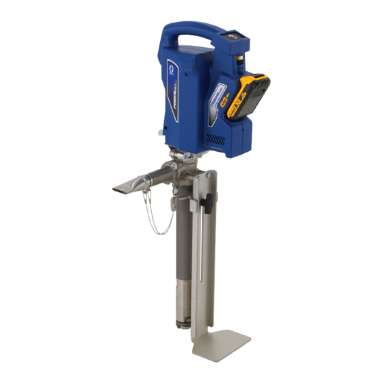
Page 7: Component Identification
Component Identification Component Identification PowerFill 3.5 Standard Series Bucket stabilizer adjustment knob Power Head Stabilizing foot bracket Dispense button Box filler nozzle Speed control Retaining clip Battery Inlet filter ProConnect cover Goose neck and pro series outlet Standard series outlet (optional accessory) Pump Bucket stabilizer... - Page 8 Component Identification PowerFill 3.5 Pro and XL Pro Series Bucket stabilizer Power Head Bucket stabilizer adjustment knob Dispense button Stabilizing foot bracket Speed control Box filler nozzle Battery Retaining clip ProConnect cover Inlet filter 14 in. Hi-Rise fill tube (23 in. High-Rise Goose-neck (optional accessory) kit optional accessory) Program/repeat button...
-
Page 9: Setup
Setup Setup Configuration Using a 1/4 in. nut driver, remove the locking screw. Remove thumb screw. Using a 1/2 in. (or 13 mm) wrench, The PowerFill is capable of being set-up with remove flanged bolt and spacer. the outlet on the left or right, depending on user preference. - Page 10 Setup Foot Bracket and Bucket Stabilizer Power Head Attach sliding bracket to foot stand with If necessary, pull piston upwards so provided thumb screw. slider will contact piston head. Using a 1/2 in. (or 13 mm) wrench, assemble 5/16 - 18 flange bolts, assemble foot bracket in desired Place slider on top of piston head.
-
Page 11: Standard Series Outlet Assembly
Setup Standard Series Outlet Attach Power Head by inserting pins into the holes on the pump. Power Head Assembly should automatically align with piston head once step 3 is complete. Assemble standard outlet to pump and using a 1/2 in. or 13 mm wrench, tighten flange head bolts. -
Page 12: Pro Series Outlet Assembly
Setup Pro Series Outlet Hand tighten wing bolt to hold tube in desired location. Assembly Assemble Pro Series outlet to pump and using a 1/2 in. or 13 mm wrench, tighten flange head bolts. Assemble Hi-Rise fill tube assembly by aligning scallop on tube with bolt located on the outlet fitting and insert it into the outlet assembly. -
Page 13: Box Filler
Setup Box Filler Align anti-rotation tab on box filler with cutout on outlet fitting and push the box filler on until the slot and groove are Ensure o-ring is in groove of box filling aligned. If difficult to push on, lubricate attachment. - Page 14 Setup Goose Neck Assembly (Optional Align scallop on goose neck with bolt located on the outlet fitting and insert it Accessory) into the outlet assembly. Lubricate with Remove standard series outlet, if water or grease if necessary. Rotate necessary, by loosening flange bolts. tube to secure.
-
Page 15: Battery Installation And Removal
Setup Battery Installation and To remove, press button on the back of the battery and pull battery from unit. Removal Always start with a fully charged Battery. Do not splash or immerse Battery or charger in water. See Battery and charger information shipped with the pump. -
Page 16: Start Up
Start Up Start Up Prior to dispensing, mix material as Apply Throat Seal Liquid (TSL) into necessary. pump throat. Insert pump into bucket of material and adjust the bucket stabilizing bracket to desired height. Install battery on the Power Head, see Battery Installation and Removal, page 15. -
Page 17: Operation
Operation Operation Pressure Relief Procedure Remove battery from pump, see Battery Installation and Removal, page 15. Slowly remove flange bolts shown below until pressure is relieved. To help prevent serious injury from pressurized fluid or splashed fluid, follow the Pressure Relief Procedure before pump is cleaned, and before equipment is serviced. -
Page 18: Using The Pump
Operation Using the Pump The variable speed control allows users to select the pump speed for precise dispensing, depending on application. Insert battery into Power Head, see Battery Installation and Removal, page 15. To operate pump, press and hold dispense button. Releasing the dispense button will stop the pump. -
Page 19: Pro-Series Operation
Pro-Series Operation Pro-Series Operation Programming the Pump While the LED light is still blinking, press and release the repeat button to set the program for that volume of material and The Pro-Series features a program/repeat to exit programming mode. This must be button that allows the user to program a completed within 10 seconds of volume of material they want to repeatedly... -
Page 20: Continuous Run Mode
Pro-Series Operation Continuous Run Mode Continuous Run Mode is used for cleaning purposes to flush or recirculate water, or to transfer a large amount of material without having to hold the button down the entire time. To make the unit continuously run, press and hold both buttons simultaneously for two seconds until the LED button begins to blink. -
Page 21: Cleaning
Cleaning Cleaning NOTE: Attach optional cleaning kit (P/N NOTE: If inlet housing is stuck, use a 18D167) and flush pump with water or screwdriver or rod for leverage to assist in compatible cleaning agent to remove any unscrewing the housing. material or residue prior to removing any parts. - Page 22 Cleaning Loosen thumb screws at top of pump Clean out inside of pump housing and and rotate pump cylinder 90 degrees. pump cylinder in bucket of water. Slide pump cylinder off of piston. Remove piston and clean in a bucket of water.
-
Page 23: Pump Re-Assembly
Cleaning Pump Re-assembly Re-assemble inlet housing and filter. Carefully insert piston rod assembly into pump housing. Be careful not to damage the throat seal. Re-assemble Power Head, see Power Head Re-Assembly, page 26. Apply Throat Seal Liquid (TSL) into pump throat. Slide cylinder onto piston, rotate onto thumb screws. - Page 24 Cleaning Cleaning Hi-Rise Filler Tube and Goose Neck Attachments Remove box filler attachment from the Put pump in bucket of water or cleaning Hi-Rise fill tube, if necessary. solution and pump until the orange ball moves through the tube, cleaning the inside diameter.
-
Page 25: Pro Connect Removal And Assembly
Pro Connect Removal and Assembly Pro Connect Removal and Assembly Power Head Removal Remove locking screw and loosen thumb screw. Rotate cover open. Set speed control to Setting 1 and jog Power Head to position the piston and slider in the bottom dead center position. This step will make re-assembly easier. - Page 26 Pro Connect Removal and Assembly Power Head Re-Assembly Attach Power Head by inserting pins into the proper holes on the pump. Power If necessary, pull piston upwards so Head should automatically align with slider will contact piston head. piston head once step 3 is complete. Place slider on top of piston head.
-
Page 27: Troubleshooting
Troubleshooting Troubleshooting Remove battery before repairing pump. Check all possible problems and causes before disassembling pump. Problem Cause Solution Re-insert battery, ensuring it is Battery is not fully seated. fully seated. Replace battery with fully Battery low on charge. Unit stops running charged one. - Page 28 Troubleshooting Problem Cause Solution Inlet filter is clogged. Remove filter and clean. Remove and clean inlet to allow Inlet valve is stuck open. for proper functionality Check inlet and ensure it is fully Inlet is not installed or loose. installed. Remove inlet and check flapper Equipment runs with Damaged inlet flapper valve.
- Page 29 Troubleshooting Problem Cause Solution Power Head feels loose or rocks Set screws located on the Tighten set screws carefully on the pump bottom of the Power Head may until the rocking has been have become loose (see image removed (see image below). below).
- Page 30 Troubleshooting Testing the Switch Functionality Follow the steps below to test your switch functionality. To Open Unit - All Units Remove battery, see Battery Installation and Removal, page 15. Perform pressure relief procedure, see Pressure Relief Procedure, page 17. Turn unit on its side and remove ten screws on clamshell.
- Page 31 Troubleshooting To Test Functionality - Standard Series Using an Ohm meter, probe the ribbon lines 2 and 3 and press the dispense button. It should read ~0 ohms (Photo If Ohm meter does not read ~0 ohms when pressing the dispense button, replace the switch.
-
Page 32: Parts
Parts Parts PowerFill 3.5 Standard, Pro, and XL Pro Ref. Torque Ref. Torque Ref. Torque Ref. Torque 3 in-lbs. (0.34 N•m) 24 in-lbs (2.71 N•m) 375 in-lbs (42 N•m) 34 ft-lbs(46 N•m) 5 in-lbs (0.56 N•m) 30 in-lbs (3.4 N•m) 140 in-lbs (16 N•m) 100 in-lbs (11.3 N•m) 10 in-lbs (1.13 N•m) - Page 33 Parts PowerFill 3.5 Standard, Pro, and XL Pro Parts List Ref. Part Description Qty. Ref. Part Description Qty. 133079 SCREW, mach, hex, washer 18F104 KIT, assembly, motor/smart control, includes 6, 13 18D170 FILTER, inlet 18F110 HOUSING, drive, 47 * 133116 O-RING, packing, 321, sub-assembly, includes 18, BUNA-N...
- Page 34 Parts Ref. Part Description Qty. BATTERY, serial, DEWALT, 17P474 Models 26B417, 26B418, 26B419 17P556 Models 26B432, 26B433, 26B434 17P557 Models 26B435, 26B439, 26B536, 26B436, 26B440, 26B537, 26B437, 26B441, 26B538 17P558 Models 26B442, 26B443, 26B444 17Y586 Models 26B472, 26B473 CHARGER, DEWALT, 20V...
-
Page 35: Technical Specifications
26B537, 26B538, 26B439, 26B440, 26B441, 26B442, 26B443, 26B444 Battery Voltage (DC) 18 V and 20 V MAX* 2.0 Ahr Li-ion Compact Battery Pack DEWALT Materials of Construction Wetted materials on all models Aluminum, stainless steel, Buna-N, and polyurethane Notes Pump damage can occur if material or water freezes in pump. -
Page 36: Recycling And Disposal
Recycling and Disposal Recycling and Disposal End of Product Life • Remove motors, batteries, circuit boards, and other electronic components. Recycle according to At the end of the product’s useful life, applicable regulations. dismantle and recycle it in a responsible •... -
Page 37: Graco Standard Warranty
Graco Standard Warranty Graco Standard Warranty Graco warrants all equipment referenced in this document which is manufactured by Graco and bearing its name to be free from defects in material and workmanship on the date of sale to the original purchaser for use. -
Page 38: Graco Information
Graco Information Graco Information For the latest information about Graco products, visit www.graco.com. For patent information, see www.graco.com/patents. TO PLACE AN ORDER, contact your Graco distributor or call 1-800-690-2894 to identify the nearest distributor. 3A8110C... - Page 39 Graco Information 3A8110C...
- Page 40 All written and visual data contained in this document reflects the latest product information available at the time of publication. Graco reserves the right to make changes at any time without notice. Original instructions. This manual contains English. MM3A8110 Graco Headquarters: Minneapolis International Offices: Belgium, China, Japan, Korea GRACO INC.