Table of Contents
Advertisement
Quick Links
Advertisement
Table of Contents

Related Manuals for Sonel MRU-200


Summary of Contents for Sonel MRU-200
- Page 3 USER MANUAL EARTH RESISTANCE METER MRU-200 ● MRU-200-GPS SONEL S. A. Wokulskiego 11 58-100 Świdnica Version 2.02 28.07.2021...
- Page 4 The MRU-200 / MRU-200-GPS meter is a modern, easy and safe measuring device. Please acquaint yourself with the present manual in order to avoid measuring errors and prevent possible problems related to operation of the meter. MRU-200 ● MRU-200-GPS – USER MANUAL...
-
Page 5: Table Of Contents
6 Power supply ....................46 6.1 Monitoring of the power supply voltage..............46 6.2 Replacement of accumulators................46 6.3 Fuse replacement ....................47 6.4 Charging of accumulators ..................47 6.5 Discharging of accumulators .................. 49 MRU-200 ● MRU-200-GPS – USER MANUAL... - Page 6 3P+C) ..56 11 Accessories ....................57 11.1 Standard accessories ..................... 57 11.2 Optional accessories ....................58 12 Positions of the meter’s cover ..............59 13 Manufacturer ....................59 14 Laboratory services ..................60 MRU-200 ● MRU-200-GPS – USER MANUAL...
-
Page 7: Safety
The MRU-200 / MRU-200-GPS meter has been designed for the purpose of measurements of earth connection and equipotential bonding, ground resistivity, as well as clamps current meas- urements. Any application that differs from those specified in the present manual may result in a damage to the device and constitute a source of danger for the user. -
Page 8: Menu
Press MENU. Using buttons highlight the required position. Press ENTER to select the option. Wireless transmission See chapter 5.3. GPS settings Using buttons select GPS on or off. Press ENTER to select the op- tion. MRU-200 ● MRU-200-GPS – USER MANUAL... -
Page 9: Measurement Settings
= AUTO), which is based upon the result of measurements of the interference voltage realized before the earth resistance measurement. The function is active if the interference ≥ 1 V. Otherwise the meter adopts the last frequency value selected from the MENU. voltage U MRU-200 ● MRU-200-GPS – USER MANUAL... -
Page 10: Calibration Of The Measurement Clamp C-3
The meter has determined the correction factor for connected clamp. The factor is saved in the memory also when the power supply of the meter is off until the following successful calibration of the clamp has been performed. MRU-200 ● MRU-200-GPS – USER MANUAL... - Page 11 After reading the intro- ductory information press ENTER. Follow on-screen prompts displayed by the meter and short H and E sockets with a wire. Connect ERP-1 adapter to the terminal of the clamps. Turn ERP-1 adapter ON. MRU-200 ● MRU-200-GPS – USER MANUAL...
- Page 12 The meter has determined the correction factor for connected clamp. The factor is saved in the memory also when the power supply of the meter is off until the following successful calibration of the clamp has been performed. MRU-200 ● MRU-200-GPS – USER MANUAL...
-
Page 13: Earth Resistivity Settings
COEFFICIENT OUT OF RANGE. and/or replace the CALIBRATION ABORTED. PRESS clamp. ENTER 2.3.3 Earth resistivity settings Using buttons select the result and the distance unit and press ENTER to confirm. MRU-200 ● MRU-200-GPS – USER MANUAL... -
Page 14: Meter Settings
2.4.3 AUTO-OFF settings The setting determines the time before the automatic turning-off of the device when it is not in use. Use buttons to set the time or AUTO-OFF disable, press ENTER. MRU-200 ● MRU-200-GPS – USER MANUAL... -
Page 15: Display Settings
(Day, month, hour, minute). Use buttons to set the value. Once the date and time have been set, press ENTER. 2.4.6 Battery discharging The procedure is fully described in chapter 6.5. MRU-200 ● MRU-200-GPS – USER MANUAL... -
Page 16: Programme Update
Before you proceed to updating the programme, download from the manufacturer’s web page (www.sonel.pl) the meter programming software, install it in the computer and connect the meter to the computer. Having chosen the Program update in the MENU, proceed in accordance with the instructions displayed by the programme. -
Page 17: Measurements
Connect the object being measured to the terminals S and E of the meter. The meter is ready for measurement. The auxiliary display shows the value of the interference voltage and its fre- quency. The setting bat shows the mains frequency set in the MENU. MRU-200 ● MRU-200-GPS – USER MANUAL... -
Page 18: Calibration Of The Test Leads
(auto-zeroing). In order to do so the measurement function 2P includes the AUTOZERO subfunction. 3.2.1 Auto-zeroing on Turn the meter on. Set the rotational function selector at 2P. Press F1. MRU-200 ● MRU-200-GPS – USER MANUAL... -
Page 19: Auto-Zeroing Off
Turn the meter on. Set the rotational function selector at 2P. Press F1. Separate the test leads. Press START. Once the auto-zeroing function has been turned off, the legend AUTOZERO will be no long- er displayed. MRU-200 ● MRU-200-GPS – USER MANUAL... -
Page 20: Earth Resistance Measurement With 3-Pole Method (R 3P)
The meter is ready for measurement. The auxiliary display shows the value of the interference voltage and its fre- quency. The setting bar shows the mains frequency set in the MENU. MRU-200 ● MRU-200-GPS – USER MANUAL... - Page 21 Additional uncertainty caused by the resistance of the electrodes Displayed, when δ>30% By pressing the F4 button you can display GPS coordinates. The result is displayed for 20 s. It may be displayed again when ENTER is pressed. MRU-200 ● MRU-200-GPS – USER MANUAL...
- Page 22 The uncertainty of the electrode resistance >30%. (Uncer- LIMIT! tainties calculated on the basis of the measured values) The value of the interfering signal is too high, NOISE! the result may be distorted by additional uncertainty. MRU-200 ● MRU-200-GPS – USER MANUAL...
-
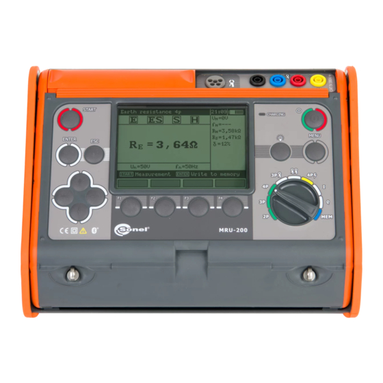
Page 23: Earth Resistance Measurement With 4-Wire Method (R 4P)
The meter is ready for measurement. The auxiliary display shows the value of the interference voltage and its fre- quency. The setting bar shows the mains frequency set in the MENU. MRU-200 ● MRU-200-GPS – USER MANUAL... - Page 24 Additional uncertainty caused by the resistance of the electrodes By pressing the F4 button you can display GPS coordinates. The result is displayed for 20 s. It be displayed again when ENTER is pressed. MRU-200 ● MRU-200-GPS – USER MANUAL...
- Page 25 The uncertainty of the electrode resistance > 30%. (Un- LIMIT! certainties calculated on the basis of the measured val- ues) The value of the interfering signal is too high, NOISE! the result may be distorted by additional uncertainty. MRU-200 ● MRU-200-GPS – USER MANUAL...
-
Page 26: Earth Resistance Measurement With 3-Pole Method With Additional Clamp
The auxiliary display shows the value of the interference voltage and its frequen- cy. The setting bar shows the mains fre- quency set in the MENU. Press button F2 to select measurement with C-3 clamp. MRU-200 ● MRU-200-GPS – USER MANUAL... - Page 27 ENTER. Press START in order for the test to commence measurement. Read out the result. Current electrode resistance Voltage electrode resistance Additional uncertainty caused by the resistance of the electrodes. MRU-200 ● MRU-200-GPS – USER MANUAL...
- Page 28 80-centimetre electrode. Check also the test leads and make sure MRU-200 ● MRU-200-GPS – USER MANUAL...
-
Page 29: (R E 3P+Erp-1)
The tested leg of the pole, the current electrode and the voltage electrode should be arranged in one line. Clamps should be attached to the tested leg of the pole below the connection point of E lead. MRU-200 ● MRU-200-GPS – USER MANUAL... - Page 30 Select voltage measurement as described in par. 3.5. Press F2 button to select the measurement in ERP-1. buttons to select the meas- urement with ERP-1, press ENTER. MRU-200 ● MRU-200-GPS – USER MANUAL...
- Page 31 Press F3 button to select the number of pole legs. buttons to select the number of pole legs, press ENTER. Press START. Follow the command on the screen and fix the clamps to the first leg (if not already done). MRU-200 ● MRU-200-GPS – USER MANUAL...
- Page 32 5 seconds the resistance result "Rn", the device displays the resultant earth resistance R Use buttons to change results displayed in the window on the right side of the screen. By pressing the F4 button you can display GPS coordinates. MRU-200 ● MRU-200-GPS – USER MANUAL...
-
Page 33: Earth Resistance Measurement With Two-Clamp Method (2C)
The meter is ready for measurement. The auxiliary display shows the value of the leakage current passing through the clamp and its frequency. Press START In order for the test to com- mence measurement. MRU-200 ● MRU-200-GPS – USER MANUAL... - Page 34 The voltage on the measurement points exceeds 24 V >24V! but lower than 40 V, the measurement is blocked. The value of the interfering signal is too high, NOISE! the result may be distorted by additional uncertainty. MRU-200 ● MRU-200-GPS – USER MANUAL...
-
Page 35: Earth Impedance Measurement With Impulse Method (R 3.9 Current Measurement (I)
EN 62305-1 Lightning protection – Section 1. General Requirements). t = current amplitude = pulse leading edge duration = time to semi-spike eg: 4/10 μs. The pulse shape is determined by the relation T MRU-200 ● MRU-200-GPS – USER MANUAL... - Page 36 The meter is ready for measurement. The auxiliary display shows the value of the interference voltage and its frequen- cy. The setting bar shows the pulse build up time. Press F1 in order to modify the pulse shape. MRU-200 ● MRU-200-GPS – USER MANUAL...
- Page 37 Additional uncertainty caused by the resistance of the electrodes. By pressing the F4 button you can display GPS coordinates. The result is displayed for 20 s. It may be displayed again when ENTER is pressed. MRU-200 ● MRU-200-GPS – USER MANUAL...
- Page 38 The uncertainty of the electrode resistance > 30%. (Un- LIMIT! certainties calculated on the basis of the measured val- ues) The value of the interfering signal is too high, NOISE! the result may be distorted by additional uncertainty. MRU-200 ● MRU-200-GPS – USER MANUAL...
- Page 39 ENTER. Notes: - Measurements are continuous and there is no possibility of their being saved. - Flexible clamp F series may be used solely for the purpose of measurements of currents > 1 A. MRU-200 ● MRU-200-GPS – USER MANUAL...
-
Page 40: Earth Resistivity Measurement (Ρ)
The setting bar shows the measurement voltage, mains frequency set in the MENU and the distance be- tween the electrodes. Press F1 to change the measurement voltage. MRU-200 ● MRU-200-GPS – USER MANUAL... - Page 41 Additional uncertainty caused by the resistance of the electrodes By pressing the F4 button you can display GPS coordinates. The result is displayed for 20 s. It may be displayed again when ENTER is pressed. MRU-200 ● MRU-200-GPS – USER MANUAL...
- Page 42 The uncertainty of the electrode resistance > 30%. (Un- LIMIT! certainties calculated on the basis of the measured val- ues) The value of the interfering signal is too high, NOISE! the result may be distorted by additional uncertainty. MRU-200 ● MRU-200-GPS – USER MANUAL...
-
Page 43: Memory
Memory The MRU-200 / MRU-200-GPS meters are equipped with a memory whose capacity is 990 re- sults of resistance measurements. Individual measurements are saved in memory cells. The whole memory is divided into 10 banks with 99 cells each. Each result may be saved in a cell of a defined... -
Page 44: Memory Erasing
Memory erasing Note: - During the process of memory erasing the progress bar is being displayed. Turn the meter on. Set the rotational function selector at MEM. Using the buttons highlight “Memory erasing”. Press ENTER. MRU-200 ● MRU-200-GPS – USER MANUAL... -
Page 45: Memory Browsing
20; cells 21…99 are empty and unavailable. The same principle refers to banks. If the memory is not filled in a continuous manner, then empty measurements and banks are skipped during browsing. MRU-200 ● MRU-200-GPS – USER MANUAL... -
Page 46: Data Transmission
USB cable and appropriate software. If the required accessories such have not been purchased along with the meter, then they are available from the manufacturer or an authorized distributor. The accessories may be used in case of many devices manufactured by SONEL S.A. which are equipped with the USB interface. - Page 47 Set the required code with the cursors. Note: Standard pin for Bluetooth is "123". - The data transmission may be interrupted using the ESC button. - With the USB cable active the wireless transmission is not possible. MRU-200 ● MRU-200-GPS – USER MANUAL...
-
Page 48: Power Supply
Replacement of accumulators The MRU-200 / MRU-200-GPS meter is equipped with a package of NiMH accumulators and charger. The package of accumulators is placed in a compartment. The charger is installed inside the meter casing and it may be used solely to charge the original accumulators. -
Page 49: Fuse Replacement
The end of the process of charging is signalled by: Charging concluded. In order to turn the device off, remove the power supply plug of the charger. MRU-200 ● MRU-200-GPS – USER MANUAL... - Page 50 The message is displayd for a deeply discharged while and then the precharge pro- accumulator pack- cess begins again. If after several Precharge error attempts the message: Battery temperature too high! is dis- played, replace the package. MRU-200 ● MRU-200-GPS – USER MANUAL...
-
Page 51: Discharging Of Accumulators
Keeping accumulators at high temperatures may accelerate this process even 100%. In order to prevent excessive discharge of accumulators, after which it would be necessary to format them, it is recommended to charge the accumulators from time to time (even if not in use). MRU-200 ● MRU-200-GPS – USER MANUAL... -
Page 52: Cleaning And Maintenance
Worn-out electronic equipment should be sent to a collection point in accordance with the law of worn-out electric and electronic equipment. Before the equipment is sent to a collection point, do not dismantle any elements. Observe the local regulations concerning disposal of packages, worn-out batteries and accumula- tors. MRU-200 ● MRU-200-GPS – USER MANUAL... -
Page 53: Technical Data
* For 3-pole method in 0,000…0,045 Ω range uncertainty is unspecified. Measurement of resistance of auxiliary electrodes R and R Range Resolution Accuracy 0…999 Ω 1Ω 1,00…9,99 kΩ 0,01 kΩ ±(5% (R ) + 8 digits) 10,0…19,9 kΩ 0,1 kΩ MRU-200 ● MRU-200-GPS – USER MANUAL... - Page 54 0,1 A 100 … 300 A 1,2,3,4 – clamp (diameter 52 mm) – C-3 – flexible clamp – F series – flexible clamp – FS-2 – flexible clamp – FSX-3 frequency range: 45…400 Hz MRU-200 ● MRU-200-GPS – USER MANUAL...
- Page 55 2000 m. EN 55022 Compliance statement MRU-200 / MRU-200-GPS is a class A product. In a domestic environment this product may cause radio interference in which case the user may be required to take adequate measures.
-
Page 56: Additional Data
≤ 1 kΩ within the range of the accuracy > 1 kΩ or >3.999 Ω > 1 kΩ or >1 kΩ and R MRU-200 ● MRU-200-GPS – USER MANUAL... -
Page 57: Influence Of The Auxiliary Electrodes Upon Earth Resistance Measurements For Earth Resistivity Function (Ρ)
R 3P+C The MRU-200 / MRU-200-GPS meter may perform a measurement, if the value of the interfer- ence current does not exceed 3 A RMS and the frequency complies with the value set in the MENU. -
Page 58: Influence Of Interference Current On The Result Of The Earth Resistance Measurement For Two-Clamp Method (2C)
10.2.7 Influence of interference current on the result of the earth resistance measurement for two-clamp method (2C) The MRU-200 / MRU-200-GPS meter may perform a measurement, if the value of the interfer- ence current does not exceed 3 A RMS and the frequency complies with the value set in the MENU. -
Page 59: Accessories
Cable to charge the accumulators from the car lighter socket – WAPRZLAD12SAM Accumulator charger (to be used in different countries) – WAZASZ7 Calibration certificate issued by an accredited laboratory User manual MRU-200 ● MRU-200-GPS – USER MANUAL... -
Page 60: Optional Accessories
Flexible clamp F-4A Flexible clamp FS-2 WACEGFSX3OKR WAWALXL3 Flexible clamp FSX-3 Case XL3 for the meter and accessories WAFUTL3 WAPOJ1 Case (for auxiliary electrodes 80 cm) Batteries compartment MRU-200 ● MRU-200-GPS – USER MANUAL... -
Page 61: Positions Of The Meter's Cover
SONEL S.A. Wokulskiego 11 58-100 Świdnica Poland tel. +48 74 858 38 60 fax +48 74 858 38 09 E-mail: export@sonel.pl Web page: www.sonel.pl Attention: Service repairs must be realized solely by the manufacturer. MRU-200 ● MRU-200-GPS – USER MANUAL... -
Page 62: Laboratory Services
National Metrological Institute. According to ILAC-G24 „Guidelines for determination of calibration intervals of measuring instru- ments”, SONEL S.A. recommends periodical metrological inspection of the instruments it manufac- tures no less frequently than once every 12 months.
Need help?
Do you have a question about the MRU-200 and is the answer not in the manual?
Questions and answers