
Related Manuals for Thunderstruck TSM2500 Series

Summary of Contents for Thunderstruck TSM2500 Series
- Page 1 TSM2500 Series High Efficiency Intelligent Charger ThunderStruck User Manual Ver. 1.08...
-
Page 2: Table Of Contents
Table Of Contents I. Product Overview II. Safety III. Preventing Short Circuits and Fire 1.Correct use of Breakers, Sockets and Cables 2. Correct Input Connections 3. Charging Environment Requirements IV. Regular Maintenance V. Technical Specifications VI. Parts List VII. LED Charge Light Information VIII. -
Page 3: Product Overview
These are canbus controlled chargers, which require a charge controller to initiate a charge, such as the ThunderStruck EVCC. Canbus information is available if needed for custom applications. The non-canbus 48v charger model is designed for lead acid batteries, and provide... -
Page 4: Safety
II. Safety Please do not disassemble the charger; this may cause electric shock or other injuries. If the charger needs to be connected to an AC power supply with extension cables, please make sure that the extension cable can withstand the maximum input current (GB 2.5mm2 copper core cable is recommended to be used), and limit the extension cable length within 10m. -
Page 5: Preventing Short Circuits And Fire
III. Preventing Short Circuits and Fire 1. Correct use of Breakers, Sockets and Cables Use stranded copper cables with flame-retardant jackets. The cable core diameter must be at least 2.5mm in diameter for the AC power input. 2. Prevent plugs and sockets from coming in contact with water. Note: According to statistics, 80% of electric car fires occur during charging. -
Page 6: Technical Specifications
V. Technical Specifications Rated input voltage: 220VAC 50/60Hz Input voltage range: 85~265VAC (Note: When the Input voltage is lower than 185VAC, the output power will be limited to 1.5KW) Power Factor: ≥ 0.99 @ 220VAC input, full power output; Total Harmonic Current: ≤ 5% @ 220VAC input, full power output; Nominal output voltage: 144V Maxim output voltage: 180V Rated output current: 15A... -
Page 7: Parts List
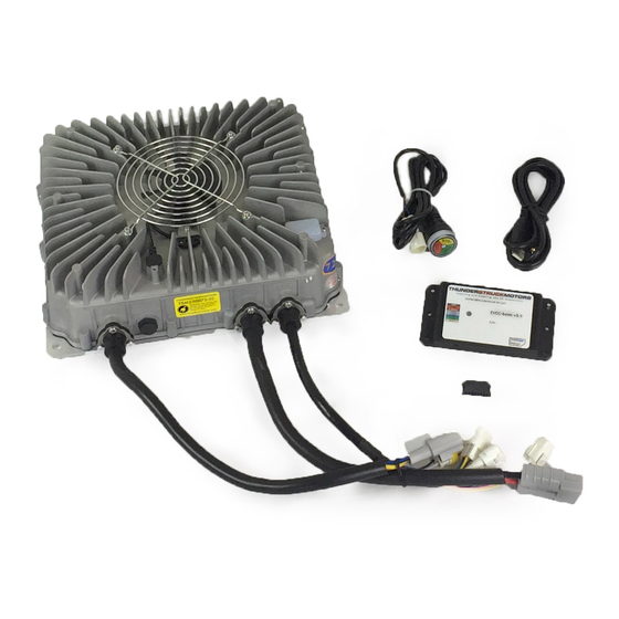
VI. Parts List A - AC Input Cables B - DC Output Cables C - Signal Cables D - Charging Indicator E Mounting plate F Shell G - Cooling Fan and Fan Cover VII. LED Charge Light Information When... Then... Red Light Flashing The pack is approximately <... -
Page 8: Input And Output Interface
VIII. Input and output interface Input Cables Terminal Model DJ7031-4.8-11 Direction of view: form the cables to terminal. Terminal Model for DJ7031-4.8-21 matching Needle No. Wire Color Wire core diameter Description brown L——Live wire blue N——Neutral wire Yellow PE——Protective grounding wire and green Output Cables Terminal Model... - Page 9 orange Driveaway DJ7021-2-11 Protection DJ7021-2-21 grey (normally closed) Wire core diameter 0.5 mm2 for all Signal wires Signal Cables Terminal Diagram (prior to 2020) Direction of view: form the cables to terminal. DJ7031Y-2.3-11 DJ7021-1.5-11 DJ7021-2-21 DJ7043-2-11...
-
Page 10: Appearance And Installation Dimensions
IX. Appearance and Installation Dimensions Do not bend the wires coming out of the charger until they have at least 50mm of space from where they enter the shell of the charger. Ensure that there is a 50mm gap above the charger to allow for proper ventilation. -
Page 11: Connections And Wiring
X. Connections and Wiring Input Cables Canbus Connection – prior to 2020 Note: The Yellow and Pink wires are not used Refer to the EVCC Manual for more details on EVCC wiring. Canbus Connection – 2020 and later Note: If wire colors do not match, then compare connector orientation. - Page 12 Remote Charge Indicator Connector Note: Remote light provided with charger AC Input Connection Options...
- Page 13 Output Cables HV DC Output Connector 12v DC Output Connector – 2020 and Later Note: During charge only, provides up to 2 amps at 12v DC Driveaway Protection Switch Output Note: EVCC can also provide driveaway protection. The above connects to a normally closed (NC) internal switch.
- Page 14 XI. Faults and Solutions Please refer to the table to help resolve common charger issues. Please email ThunderStruck Motors if troubleshooting is unsuccessful. Please include all test results and measurement details. Fault Analysis Solutions Check connectors and breaker for heat Poor connection on charger damage or open circuit.
Need help?
Do you have a question about the TSM2500 Series and is the answer not in the manual?
Questions and answers