Table of Contents

Related Manuals for Fluke 1653 B


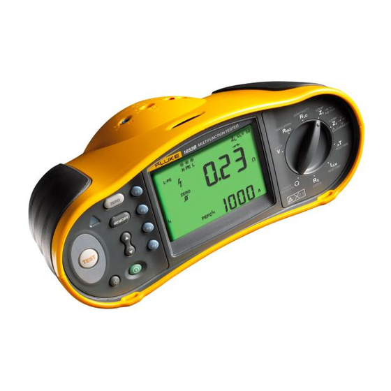
Summary of Contents for Fluke 1653 B
- Page 1 ItresE C O N S U L T O R Í A E N E R G É T I C A L A T A M - U S A A N ALI Z A D O R DE I NSTAL ACION ES BT - F LUK E 16 5 3 B Ma nual de C alib ració...
- Page 2 Manual Title: 1652C/1653B/1654B Calibration Supplement Issue: 4 Part Number: Web-Only Issue Date: 4/17 Print Date: March 2011 Page Count: Revision/Date: This supplement contains information necessary to ensure the accuracy of the above manual. © 2011-2017 Fluke Corporation. All rights reserved.
- Page 3 On page 20, replace step 4 with: 4. Place PN 1884378 on the touch pad, then touch with the probe as shown in Figure 4. On page 21, replace Figure 4 with: Fluke 5320A 5320A MULTIFUNCTION ELECTRICAL OUTPUT , HI...
- Page 4 , set the UUT for L-PE test. 3. Connect test leads to the UUT L-PE-N input jacks. Short the far end of the test leads together with a Zero Adapter (Fluke P/N 3301338). See Figure 8. 4. Press and hold for approximately three seconds until the UUT ZERO annunciator appears.
- Page 5 1652C/1653B/1654B Calibration Manual Supplement Change #3, On page 33, Table 10, add the MP12: MP12 Battery Holder 1676850 Change #4 On page 10, replace the Test Signals table with: Test Signals RCD Type Test Signal Description The waveform is a sinewave starting at zero crossing, polarity determined by phase selection (0 phase starts with low to high zero (sinusoidal) crossing, 180 phase starts with high to low zero crossing).
Need help?
Do you have a question about the 1653 B and is the answer not in the manual?
Questions and answers