Advertisement
Quick Links
Advertisement

Related Manuals for MyFlyDream Mini Crossbow


Summary of Contents for MyFlyDream Mini Crossbow
- Page 1 Mini Crossbow AutoAntennaTracker Manual V 1.15 2020-Dec-04th www.MyFlyDream.com...
-
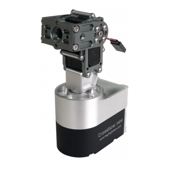
Page 2: Product Introduction
Precautions Thank you for purchasing the MyFlyDream Crossbow AAT (Automatic Antenna Tracker, hereafter referred to as Crossbow AAT). Please familiarize yourself with this product and its operation method described in this document. This product is a precision electromechanical device. Please read this document carefully to prevent damage to the device and minimize the risks of damage to property or people’s lives. -
Page 3: Installation And Wiring
MAVLink protocol, Crossbow AAT will be able to receive all flight information necessary to track the UAV through the shared TXD line of the digital radio station. 4. For more specific applications requiring custom design of the signal transmission, please contact MFD directly. MyFlyDream miniCrossbow Specifications MAX Pan-Speed 400deg/s MAX Tilt-Speed... - Page 4 Crossbow AAT requires =12V to 16V (3S~4S) DC power supply. The tracker is powered on by simply plugging the XT30 connector into the corresponding power socket of the AAT, as shown in the picture: 2. The antenna has to be mounted on the Crossbow AAT with the use of a special bracket. In...
- Page 5 AAT it is recommended to avoid using antennas made with ferromagnetic materials. Wherever possible, use non-magnetic stainless steel bolts, aluminum and other non-magnetic materials. There is 3 pin connector beside the tilt servo (in the purple circle). The diagram below shows the wiring.
- Page 6 This cable shows in the below picture is part of standard retail kit.
- Page 7 MAVLink data to PIN#1 of the RIGHT connector or to the PIN#2 of the LEFT connector. Sharing the TX line of the data radio link with mini Crossbow AAT will not affect the normal ground station operation. And don't forget to set proper baudrate in the menu of mini Crossbow to match your data radio.
- Page 8 *S.Port (SmartPort) is a telemetry system developed by FrSky. It's a inversed Serial signal. But our RX3-LEFT port and RX1-RIGHT port can only accept standard Serial data. To feed the S.Port data to mini Crossbow you need to use an "Inverter" or hack your FrSky Transmitter. 3. Test Please make sure the tripod is securely set up, and its legs are well tightened.
- Page 9 4. Downlink The mini Crossbow AAT needs a downlink to get the information of the tracking plane. Usually this is the most difficult part to get your system to work. Because you have to merge several devices came from different manufactories.
- Page 10 The advantage of VBI is that you don't need an extra dataradio if you already have a video TX and RX. These MFD products will encode the necessary data on your analog video signal (usually comes from an onboard camera). Your VideoTX emits it. Once your Video Receiver receives the video signal, and feeds the signal to a MFD tracker, the tracker will extra tracking data from the analog video signal and use the data to track.
- Page 11 the reasons is that MAVLink is not clear enough to define how to send some important data between the Plane And GCS. There are so many different MAVLink messages which can be used to send GPS Coordinates, Altitudes... Crossbow AAT needs both these 2 MAVLink messages to track. MAVLINK_MSG_ID_GPS_RAW_INT MAVLINK_MSG_ID_GLOBAL_POSITION_INT If the Crossbow AAT receives some correct MAVLink data packs (Heartbeat?) but not able to find...
- Page 12 After power on the screen shows main parameters of the current status. GPS: 12 DIST:N/A Alt: N/A AZim: N/A VLink: 0% Dir: 0 To enter/quit the menu system, hold the LEFT button for 2 seconds or longer. You can also choose "Exit" in the menu to quit the menu system. Please use the LEFT button to browse the menu.
- Page 13 The valid parameter range is [-20,20] HomePos: UsePreHome H1:D:0 H2:D:0 H3:D:0 H4:D:0 H5:D:0 AutoLoad=N Exit H1~H5 is the Home Positions which you recently have used. H1 is the most recent home position. H5 is the earliest one. The distances between your plane and the H1~H5 stored home positions are displayed in a D:XXXXX formation.
- Page 14 Valid range of these parameters are [0,4500] mA You can also use "AutoDetect" to measure the proper settings of your setup. Remember to fasten your tracker and clear all objects nearby before doing that. Because the tracker may yaw and pitch to any direction during the procedure.
- Page 15 115200 57600 38400 19200 9600 4800 1200 Exit Choose a baudrate for TX3(PIN#3) / RX3(PIN#2) of your LEFT-port. To use our Compass+GPS module you need to use 115200bps. If you use RX3 as telemetry input (MAVLink / S.Port-Inv), set the baudrate according to your devices. R-Baudrate: Almost same as above.
- Page 16 OSDLevel : Brightness Level:90 Exit Choose the OSD(OnScreenDisplay) brightness level of the tracker. The tracker is able to overlay some graphics information on the analog video signal. Higher value will choose brighter OSD images. With the CAN-BUS and our new "FlyTogether" feature, users now can connect up to 10 trackers.
- Page 17 12:40:22 Hw:1 Exit This screen shows version number of the firmware (1.83) and Hardware (1) Factory: Test YawTest PitchTest AllTest CoreData Exit This screen is reserved for the manufacture.
- Page 18 Appendix A: Some Dimensions of the tracker and the mounting interface of antenna Appendix B How to update Firmware for the mini Crossbow...
- Page 19 MFD FW & update tool (you need .Net 4.0 framework to use it) http://www.myflydream.com/inc/lib/download/download.php?DId=63 >>> Choose "38400" baudrate for the Left Connector of mini Crossbow <<< Run MFD_Update.exe. Choose "mini_AAT". Choose correct COM port of your computer. Browse for the firmware on your computer by clicking "choose the file".
- Page 20 CompassMod=Always). And you don't need to SetHome before takeoff. Please align your GPS+Compass module parellel with the mini Crossbow main unit as the below picture. Connect the GPS+Compass module to the left port of the Crossbow. Then choose 115200 in the "L-Baudrate"...
Need help?
Do you have a question about the Mini Crossbow and is the answer not in the manual?
Questions and answers