
Related Manuals for Calrec M3


Summary of Contents for Calrec M3
- Page 1 OPERATOR MANUAL Calrec Audio Ltd Nutclough Mill Hebden Bridge West Yorkshire HX7 8EZ England Tel: +44 (0) 1422 842159 Fax: +44 (0) 1422 845244 Email: enquiries@calrec.com Website: www.calrec.com...
- Page 2 Modifications to this equipment by any party other than Calrec Audio Limited may invalidate EMC and safety features designed into this equipment. Calrec Audio Limited can not be liable for any legal proceedings or problems that may arise relating to such modifications.
- Page 3 ....................................IMPORTANT HEALTH AND SAFETY INFORMATION • • • • • This equipment must be EARTHED. • • • • • Only suitably trained personnel should service this equipment. • • • • • Please read and take note of all warning and informative labels. •...
-
Page 4: Table Of Contents
....................................CONTENTS TECHNICAL CUSTOMER SUPPORT ..................... 6 PRODUCT WARRANTY ........................7 INTRODUCTION..........................8 PRINCIPLE FEATURES ........................9 1.0 INSTALLATION ........................11-13 2.0 LAYOUT & PROFILES ......................15 SMALL CHASSIS TYPICAL LAYOUT ............... 16 MODULE OPTIONS ..............17 MEDIUM CHASSIS TYPICAL LAYOUT ............... - Page 5 ....................................4.0 MODULES & PANELS DESCRIPTION ................... 45 PQ5122 MONO MIC/LINE DUAL INPUT CHANNEL ......... 46-47 BQ5124 STEREO LINE INPUT CHANNEL ............48-49 PQ5123 STEREO MIC INPUT CHANNEL ............50-51 XL5125 MONO GROUP ..................52-53 XL5126 STEREO GROUP ................. 54-55 LC5127 MAIN OUTPUT 1 AND AUX MASTERS ..........
-
Page 6: Technical Customer Support
Supply of replacement components Supply of documentation Technical advice by telephone If you have any other issues regarding your Calrec purchase, then please contact us and we will do our best to help. Calrec welcomes all Customer feedback. Stephen Brant... -
Page 7: Product Warranty
REPAIRS If you need to return goods to Calrec, for whatever reason, please contact the Company beforehand in order that you can receive advice on the best method of returning the goods & that a repair order reference number can be issued. -
Page 8: Introduction
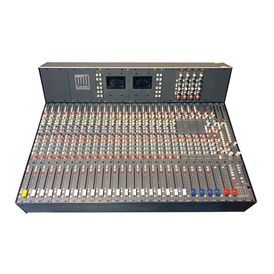
The Calrec M3 is a high quality, mixing console which provides superior audio and operational performance in a choice of compact packages. It’s ease of use makes the M3 ideal for novice operators as well as those who can make full use of the wealth of facilities provided. As with all Calrec products, the M3 has been designed for long life in real world environments, and offers high levels of reliability and excellent return on investment. -
Page 9: Principle Features
....................................PRINCIPLE FEATURES Available in three frame sizes: - Up to 10 Channels in the small frame - Up to 24 Channels in the medium frame - Up to 38 Channels in the large frame Optional Upstand Chassis Choice of 3 channel modules: - Mono with dual mic/line inputs - Stereo with stereo mic/line inputs - Stereo with line inputs... - Page 10 ....................................
-
Page 11: 1.0 Installation
....................................1.0 Installation... - Page 12 Complete the user registration form • The M3 has the internal switching options set as requested in the customer questionnaire. If the questionnaire has not been submitted, then the console will be set to the standard default DIL switch settings shown in section 5. If however this is not the preferred set-up, then please refer to section 5, which explains the options available using the DIL switches.
- Page 13 ....................................MOUNTING THE M3 The M3 console has been designed to allow for maximum flexibility of use, in that it can be placed into a site for temporary operation, or fixed into a permanent location. All console chassis sizes have been designed to allow for mounting in several different ways, as follows: Directly on top of a table top or small equipment rack/trolley.
- Page 14 ....................................
-
Page 15: 2.0 Layout & Profiles
....................................2.0 Layout & Profiles... -
Page 16: Typical Layout
....................................SMALL CHASSIS TYPICAL LAYOUT (0579-17) -
Page 17: Module Options
....................................SMALL CHASSIS MODULE OPTIONS This table shows which slots each module can occupy. The greyed out areas indicate slots into which the module cannot be fitted. -
Page 18: Typical Layout
....................................MEDIUM CHASSIS TYPICAL LAYOUT (0579-18) -
Page 19: Module Options
....................................MEDIUM CHASSIS MODULE OPTIONS This table shows which slots each module can occupy. The greyed out areas indicate slots into which the module cannot be fitted. -
Page 20: Typical Layout
....................................LARGE CHASSIS TYPICAL LAYOUT (5065-1) -
Page 21: Module Options
....................................LARGE CHASSIS MODULE OPTIONS This table shows which slots each module can occupy. The greyed out areas indicate slots into which the module cannot be fitted. -
Page 22: Plan, Elevation And General Arrangement Details
....................................PLAN, ELEVATION AND GENERAL ARRANGEMENT DETAILS SMALL CHASSIS - EM5270 (0579-12) Supplied with an internal Power Supply Unit as standard, but an external version is available upon request (EM5271). -
Page 23: Medium Chassis
....................................PLAN, ELEVATION AND GENERAL ARRANGEMENT DETAILS MEDIUM CHASSIS - EM5273 (0579-13) -
Page 24: Large Chassis
....................................PLAN, ELEVATION AND GENERAL ARRANGEMENT DETAILS LARGE CHASSIS - EM5274 (0579-50) -
Page 25: Optional Upstand
....................................OPTIONAL UPSTAND All chassis sizes of the M3 console may be supplied with an optional upstand which can house a selection of Calrec level meters. These units derive their audio and power interface from the main M3 chassis. The upstand option must be specified at time of order. There is also a seperate 19” rack mounted meter bridge available. -
Page 26: Medium Chassis With Upstand
....................................MEDIUM CHASSIS WITH UPSTAND - EM5250 (0579-32) -
Page 27: Large Chassis With Upstand
....................................LARGE CHASSIS WITH UPSTAND - EM5275 (0579-45) An optional stand is available with the large chassis only. (0579-44) - Page 28 ....................................
-
Page 29: Connections And Specifications
....................................3.0 Connections & Specifications... -
Page 30: Connections
....................................CONNECTIONS The M3 uses XLR-3 fixed (panel mounted) female (socket) connectors for Channel Mic and Line level inputs and direct inputs to groups and mains. Main, monitor and Aux outputs are on XLR-3 fixed (panel mounted) male (plug) -
Page 31: Specification
....................................SPECIFICATION Measurements are with 22-22KHz filters unless otherwise stated. All specifications are in the frequency range 40-15KHz unless otherwise stated. Measurements specified are with EQ and dynamics out of circuit. 0dBu = 0.775 volts RMS. dBq = CCIR QUASI PEAK. -
Page 32: Small Chassis
....................................SMALL CHASSIS REAR AND METER BRIDGE INTERFACE CONNECTOR DETAILS External PSU Internal PSU (0579-56) (0579-57) Meter Bridge (0579-59) -
Page 33: Medium Chassis
....................................MEDIUM CHASSIS REAR AND METER BRIDGE INTERFACE CONNECTOR DETAILS (0579-58) (0579-60) -
Page 34: Large Chassis
....................................LARGE CHASSIS REAR AND METER BRIDGE INTERFACE CONNECTOR DETAILS (0579-46) (0579-61) -
Page 35: Rack Mounted Meter Bridge
....................................RACK MOUNTED METER BRIDGE INTERFACE CONNECTOR DETAILS (0579-62) -
Page 36: Inputs - Xlr's
....................................INPUTS - XLR’s XLR 3 Connector Pin Information (fixed sockets on console) Pin 2 - Hot, or Phase Pin 3 - Cold, or Anti-phase Pin 1 - Chassis or Earth Channel Inputs Module Type fitted XLR Ref Circuit for channel slots 1-10 (Small chassis), slots 1-24 (Medium chassis) or slots 1-38 (Large chassis - unless group modules fitted). -
Page 37: Outputs - Xlr's
....................................OUTPUTS - XLR’s XLR 3 Connector Pin Information (fixed plugs on console) Pin 2 - Hot, or Phase Pin 3 - Cold, or Anti-phase Pin 1 - Chassis or Earth Main Output 1 Module Type fitted XLR Ref Circuit for Main module in Main 1 slot LC5127 LINE Output 1L (Main 1) -
Page 38: Small Chassis
....................................SMALL CHASSIS OUTPUT GUIDE Connector INS / DIR 1-4 * INS / DIR 9-10 MN INS 1&2 ANCILLARY 1 PRINCIPLE O/P'S MONITOR Type 50F D-TYPE 50F D-TYPE 50F D-TYPE 50F D-TYPE 50F D-TYPE (Free Male Plug) (Free Male Plug) (Free Male Plug) (Free Male Plug) (Free Male Plug) -
Page 39: Medium Chassis
....................................MEDIUM CHASSIS OUTPUT GUIDE INS / DIR 23-24 MN INS Connector INS / DIR 1-4 * INS / DIR 13-14 1&2 ANCILLARY 2 ANCILLARY 1 PRINCIPLE O/P'S MONITOR Type 50F D-TYPE 50F D-TYPE 50F D-TYPE 50F D-TYPE 50F D-TYPE 50F D-TYPE 50F D-TYPE (Free Male Plug) -
Page 40: Large Chassis
....................................LARGE CHASSIS OUTPUT GUIDE Connector INS / DIR 1-4 * INS / DIR 13-14** INS / DIR 37-38 MN INS 1&2 ANCILLARY 2 *** ANCILLARY 1 PRINCIPLE O/P'S MONITOR Type 50F D-TYPE 50F D-TYPE 50F D-TYPE 50F D-TYPE 50F D-TYPE 50F D-TYPE 50F D-TYPE... -
Page 41: Common Powering Schedule
....................................COMMON POWERING SCHEDULE External DC Back-up Power Input for Sump Power Output to Metering Internally powered Small Chassis only DC Power Inputs for Externally powered Small, Medium or Large Chassis types... -
Page 42: Common Metering Schedule
....................................COMMON METERING SCHEDULE Metering SCSI Lead Connections Metering Power Input Meter Interface External Connections... -
Page 43: Block Diagram
....................................BLOCK DIAGRAM SMALL CHASSIS UP TO 10 CHANNELS MEDIUM CHASSIS UP TO 24 CHANNELS LARGE CHASSIS UP TO 38 CHANNELS MAXIMUM 4 MONO OR STEREO GROUPS CAN BE FITTED (0579-27) - Page 44 ....................................
-
Page 45: 4.0 Modules & Panels Description
....................................4.0 Modules & Panels Description... -
Page 46: Pq5122 Mono Mic/Line Dual Input Channel
....................................PQ5122 MONO MIC/LINE DUAL INPUT CHANNEL Routing to 2 main Stereo outputs up to 4 Mono or Stereo groups. Tone Red button switches alignment tone to the channel post mic gain control but pre the trim - Inhibited on air, but can be internally set to be permanently enabled. Microphone phantom power. - Page 47 ....................................
-
Page 48: Bq5124 Stereo Line Input Channel
....................................BQ5124 STEREO LINE INPUT CHANNEL Routing 2 main stereo outputs and up to 4 mono or stereo groups Tone Red button switches alignment tone to the channel post mic gain control but pre the trim - Inhibited on air. Input balance control. - Page 49 ....................................
-
Page 50: Pq5123 Stereo Mic Input Channel
....................................PQ5123 STEREO MIC INPUT CHANNEL Routing to 2 main Stereo outputs up to 4 Mono or Stereo groups. Optional routing to mono groups - left to odds, right to evens. Tone Red button switches alignment tone to the channel post mic gain control but pre the trim - Inhibited on air. - Page 51 ....................................
-
Page 52: Xl5125 Mono Group
....................................XL5125 MONO GROUP Group routing to 2 main Stereo outputs. Group direct input routing to 2 main Stereo outputs to group mixer. Aux 1-3 from direct button switches aux 1-3 to group direct input. Direct AFL Latching button routes direct input after fader signal exclusively to monitor loudspeaker. - Page 53 ....................................
-
Page 54: Xl5126 Stereo Group
....................................XL5126 STEREO GROUP Group routing to 2 main Stereo outputs. Group direct input routing to 2 main Stereo outputs to group mixer. Aux 1-3 from direct button switches aux 1-3 to group direct input. Direct AFL Latching button routes direct input after fader signal exclusively to monitor loudspeaker. - Page 55 ....................................
-
Page 56: Lc5127 Main Output 1 And Aux Masters
....................................LC5127 MAIN OUTPUT 1 AND AUX MASTERS Direct AFL Latching button routes direct input after fader signal exclusively to monitor loudspeaker. Direct PFL Latching button routes direct input pre fader signal to small PFL loudspeaker. Direct CUT : Latching button cuts direct input signal. - Page 57 ....................................
-
Page 58: Lc5128 Main Output 2, Tone & Talkback
....................................LC5128 MAIN OUTPUT 2, TONE & TALKBACK Routes to Main 1. ON AIR Pushbutton with red LED. Inhibits tone and talkback within the console and closes relay contact for interface to other areas. POWER Red LED flashes to indicate a failure of either the PSU or the fan (if fitted). Direct AFL Latching button routes direct input post fader, exclusively to monitor loudspeaker. - Page 59 ....................................
-
Page 60: Ml4952 Monitor 1
....................................ML4952 MONITOR 1 LEVEL BARGRAPH Displays level of left channel of meter select output (internally selectable for PPM/VU and 0dB reference level). Red indicator - illuminated when any AFL selection is made. CONTROL ROOM MONITOR SELECTOR - 15 way selector with the following sources: - 4 external Stereo inputs 1 to 4, Green LEDs (Labelled A1-A4 on schematic). -
Page 61: Ml4953 Monitor 2
....................................ML4953 MONITOR 2 LEVEL BARGRAPH Displays level of right channel of meter select output (internally selectable for PPM/VU and 0dB reference level). METER SELECTOR - 12 way selector with the following sources: TONE Sends line up tone to meters, Red LED. Follows control room monitor selector, Green LED. -
Page 62: Dl3678-2 Stereo Compressor/Limiter
....................................DL3678-2 STEREO COMPRESSOR/LIMITER Stereo Limiter: Ratio Fixed 100/1. Threshold -4/+16dBu variable. Attack Fixed 100 µs. Recovery 0.075 to 4 secs variable with AUTO facility: 0.1 to 1.5 secs (programme dependent). Peak Limit Yellow LED indicator. Limiter On button with Yellow LED indication. Stereo Compressor: Ratio 1.5/10 variable. -
Page 63: Df4041-2 Expander/Gate
....................................DF4041-2 EXPANDER/GATE Stereo Expander: Ratio : Normal, varies with level 1.5/1 to 5/1 - Fixed 2/1 (button) Threshold : 0/-40dBu variable Attack : Normal 4 m-sec. FAST (button) 50µs Recovery : 75ms to 4 sec variable Depth : 0/40dB variable (extent of expansion below threshold) Bargraph : Up to 20dB gain reduction Links... -
Page 64: Ml3679 Studio Ls Control
....................................ML3679 STUDIO LS CONTROL 6 Electronic cancelling inputs - Yellow LEDs including 3 external inputs. Gain controls 0dB to OFF. CUT button with Yellow LED - cuts LS automatically when any channel selected to Mic and routed to the Main output either directly or via a group is opened. Separate studio headphones outputs. -
Page 65: My4994/My4994-2 Meter Selector
....................................MY4994/MY4994-2 METER SELECTOR Selections from labelled sources. Yellow LEDs - Electronic cancelling set. M/S latching & S+20. Red LEDs meter selector can be internally selected to automatically switch the meaning to m/s when a mono source is selected and to automatically reduce the metering by -3dB if required. -
Page 66: Mu3663 Stereo Ppm A/B
....................................MU3663 STEREO PPM A/B Stereo PPM with Red/Green needles and illumination. Internal PPM driver. -
Page 67: Mu3801 Stereo Ppm M/S
....................................MU3801 STEREO PPM M/S Stereo PPM with White/Orange needles and illumination. Internal PPM driver. -
Page 68: Mu3695 Twin Mono Ppm
....................................MU3695 TWIN MONO PPM Stereo PPM with Red/Green needles and illumination. Internal PPM driver. -
Page 69: Mv5154 Single Stereo Vu Meter
....................................MV5154 SINGLE STEREO VU METER Large VU Meter with illumination. Meter has Red and Green needles. 0VU selectable to +4dBu (Normal). Internal buffer amplifier. -
Page 70: Mv4383 Single Mono Vu Meter
....................................MV4383 SINGLE MONO VU METER Large VU Meter with illumination. 0VU represents +4dBu. Internal buffer amplifier. -
Page 71: Mv4656 Twin Mono Vu Meter
....................................MV4656 TWIN MONO VU METER VU meters with illumination. Internal buffer amplifiers. -
Page 72: Bargraph Options
....................................BARGRAPH OPTIONS MU3804-2 MU4333-2 MU3807-2 MU5155 MU4710 LARGE STEREO LARGE STEREO SMALL STEREO SMALL STEREO MONO BARGRAPH BARGRAPH BARGRAPH BARGRAPH BARGRAPH (Red/Green) (Green/Red) (Red/Green) (Green/Red) (Green) Twin LED bargraphs - 40 LEDs each for good resolution. Bars brighten at 0dB representing +6 or +8 dBu for PPM or +4dBu (SCALE 0) for VU (set internally). -
Page 73: Mu4078-2 Phase Bargraph
....................................MU4078-2 PHASE BARGRAPH LED Bargraph. Upper section representing good phase coherence is GREEN. Lower section representing poor phase coherence is RED. Spot moves dynamically. -
Page 74: Ls3803 Pfl Loudspeaker
....................................LS3803 PFL LOUDSPEAKER Module can be set for Left, Right or Mono use. Module can receive Reverse Talkback plus an extra intercom signal if required. -
Page 75: Yw5245 Broadcast Facilities Panel
....................................YW5245 BROADCAST FACILITIES PANEL PSU FAIL / CANCEL - Red LED flashes when a PSU or part of a PSU has failed. Flashing may be cancelled by button but will resume with a further failure or if the console is switched off and on again. -
Page 76: Zn3018-7 2Ru Externalpower Supply Unit
....................................ZN3018-7 2RU EXTERNALPOWER SUPPLY UNIT A Calrec designed special unit to provide + 16 volts audio power, 8 volts logic power (stabilised in modules at 5 volts where required), and 48 volts phantom power suitable for approximately 16 channels each in a typical console. It is recommended that there be a second external power supply in the system to act as a “Hot”... -
Page 77: Zn5210 1Ru External Power Supply Unit
....................................ZN5210 1RU EXTERNAL POWER SUPPLY UNIT A Calrec designed PSU to provide +18 volts audio power, 9 volts logic power (stabilised in modules to 5 volts where required) and 48 volts phantom power. It is recommended that there be a second external power supply in the system to act as a “Hot”... - Page 78 ....................................
-
Page 79: 5.0 Dil Switch Information
....................................5.0 DIL Switch Information... -
Page 80: Pq5122 Mono Mic/Line Dual Input Channel
....................................DIL SWITCH SETTINGS - PQ5122 MONO MIC/LINE DUAL INPUT CHANNEL Mono channel 2nd Input can be internally set to either Mic or Line. (Selection of either Input 1 or 2 is done via a switch on the front panel). SW 19 Standard default settings... - Page 81 ....................................Each channel has the option of sending to a Direct Output or to the Mix Minus Bus (via a switch on the front panel). Both options can be set internally to be either pre or post fader. Direct Output - Post fader SW 44 Standard default settings Direct Output - Pre fader...
-
Page 82: Bq5124 Stereo Line Input Channel
....................................DIL SWITCH SETTINGS - BQ5124 STEREO LINE INPUT CHANNEL Channel Insert Go signal can be taken either Pre or Post fader, or bypassed altogether if not required for use. The signal is always present at the Insert Go connector in all conditions. - Page 83 ....................................Each channel has the option of sending to a Direct Output or to the Mix Minus Bus (via a switch on the front panel). Both options can be set internally to be either pre or post fader. Direct Output - Post fader SW 37 Standard default settings Direct Output - Pre fader...
-
Page 84: Pq5123 Stereo Mic Input Channel
....................................DIL SWITCH SETTINGS - PQ5123 STEREO MIC INPUT CHANNEL Channel Insert Go signal can be taken either Pre or Post fader, or bypassed altogether if not required for use. The signal is always present at the Insert Go connector in all conditions. Insert - Pre fader SW 2 SW 19... - Page 85 ....................................Each channel has the option of sending to a Direct Output or to the Mix Minus Bus (via a switch on the front panel). Both options can be set internally to be either pre or post fader. Direct Output - Post fader SW 37 Standard default settings Direct Output - Pre fader...
-
Page 86: Xl5125 Mono Group
....................................DIL SWITCH SETTINGS - XL5125 MONO GROUP Standard default settings... - Page 87 ....................................Mono Groups have the option of being fed with either a mono mix signal or a Left /Right split to pairs of group mono modules. Left signal going to positions 1 & 3, Right to 2 & 4. L/R Input Mix ON SW 2 Standard default settings L/R split to gps 1&3 / 2&4 SW 2...
-
Page 88: Xl5126 Stereo Group
....................................DIL SWITCH SETTINGS - XL5126 STEREO GROUP Standard default settings... - Page 89 ....................................When Aux 1 PA Inhibit is enabled, it allows a signal only to be fed to the audience PA system only whilst the fader is open. Aux 1 PA Inhibit enabled SW 7 to follow fader Aux 1 PA Inhibit not SW 7 Standard default settings selected...
-
Page 90: Lc5128 Main Output 2, Tone & Talkback
....................................DIL SWITCH SETTINGS - LC5128 MAIN OUTPUT 2, TONE & TALKBACK Standard default settings... - Page 91 ....................................Main stereo Line-up tone can be set to sequence in several styles, which are: Left signal only interrupted once every 3 seconds. (EBU) Left signal interrupted once every 4 seconds and the Right signal twice in the intervening period. (GLITS) Right signal only interrupted once every 3 seconds.
-
Page 92: Ml4952 Monitor 1
....................................DIL SWITCH SETTINGS - ML4952 MONITOR 1 Standard default settings... - Page 93 ....................................The bargraph characteristics can be set to display as either PPM or VU. SW 5 Standard default settings SW 5 On the bargraph display the bar at the ‘0’ position can be set to brighten, when the signal is either 0dBu, +4dBu, +6dBu or +8dBu.
-
Page 94: Ml4953 Monitor 2
....................................DIL SWITCH SETTINGS - ML4953 MONITOR 2 Standard default settings... - Page 95 ....................................The bargraph characteristics can be set to display as either PPM or VU. SW 18 Standard default settings SW 18 On the bargraph display the bar at the ‘0’ position can be set to brighten, when the signal is either 0dBu, +4dBu, +6dBu or +8dBu.
-
Page 96: Dl3678-2 Stereo Compressor Limiter
....................................DIL SWITCH SETTINGS - DL3678-2 STEREO COMPRESSOR LIMITER SW2 "M" detection:- DOWN OFF. ON = Detection of reduced mono Standard default setting signal into side chain. The compressor and limiter normally respond to the higher of the left and right signals. -
Page 97: Ml3679 Studio Ls Control
....................................DIL SWITCH SETTINGS - ML3679 STUDIO LS CONTROL CUT TB OPTION ML812-326 SW8 Cut Talkback = OFF = No effect = TALKBACK heard. DOWN = ON TALKBACK as well as loudspeaker signals Standard default cut by cut button and REMOTE CUT. setting... -
Page 98: My4994 / My4994-2 Meter Selector
....................................DIL SWITCH SETTINGS - MY4994 / MY4994-2 METER SELECTOR SW16 AUTO M/S ON MONO SELS AUTO M-3 ON MONO SELS Standard default settings SW15 MY812-324 The meter selector can be set to automatically switch the metering to M/S when a mono source is selected. -
Page 99: Hn5255 Meter Backplane
....................................DIL SWITCH SETTINGS - HN5255 METER BACKPLANE If group or PFL circuits are fed from external connectors, the internal circuit switches 4, 5 and 6 must be opened to remove the internal feeds. GROUP OR EXTERNAL DIGITAL INPUTS FED EXTERNALLY: 1-4 OFF = GROUP 4 5-8 OFF =... -
Page 100: Mv4383 Single Mono Vu Meter
....................................DIL SWITCH SETTINGS - MV4383 SINGLE MONO VU METER MN812-355 1 Card fitted per unit. Standard SW 3 Section 1 & 3 - ON - Select RIGHT meter feed to be source. default setting Section 2 & 4 - ON - Select LEFT meter feed to be source. for L/R SW 1 Section 1 - ON - PPM Characteristic. -
Page 101: Mv4656 Twin Mono Vu Meter
....................................DIL SWITCH SETTINGS - MV4656 TWIN MONO VU METER MN812-355 2 Cards fitted per unit - 1 for each meter. Standard SW 3 Section 1 & 3 - ON - Select RIGHT meter feed to be source. default setting Section 2 &... -
Page 102: Bargraph Options
....................................DIL SWITCH SETTINGS - BARGRAPH OPTIONS MU3804-2 LARGE STEREO BARGRAPH MU4333-2 LARGE STEREO BARGRAPH - REVERSED COLOURS MU3807-2 STEREO BARGRAPH MU5155 STEREO BARGRAPH - REVERSED COLOURS MU4710 MONO BARGRAPH (SWITCHES 4, 5 AND 6 DO NOT FUNCTION) PLEASE NOTE The following switches should be set to all VU or all PPM to achieve proper performance. - Page 103 ....................................SW1 +6dBu at the scale "0" position (PPM only):- LEFT BAR ON = +6dBu at scale "0". RIGHT BAR DOWN OFF = +8dBu at scale "0". SW2 PPM/VU characteristics, LEFT BAR :- LEFT RIGHT SW3 PPM/VU characteristics, LEFT BAR :- LEFT RIGHT SW4 PPM/VU characteristics (Not available on MU4710):-...
-
Page 104: Mu3695 Twin Mono Ppm
....................................DIL SWITCH SETTINGS - MU3695 TWIN MONO PPM LINK LINK PPM / VU VU / PPM 812 - 335 J4 & J5 LINKS:- Add links as indicated for PPM or into centre and end slot for VU. The Standard Default settings will be set for PPM. -
Page 105: Ls3803 Pfl Loudspeaker
....................................DIL SWITCH SETTINGS - LS3803 PFL LOUDSPEAKER IF LS IS FOR USE IN EITHER THE STEREO LEFT POSITION OR MONO 1 = ON 2 = ON 3 = OFF 4 = OFF IF LS IS FOR USE IN THE STEREO RIGHT POSITION 1 = OFF 2 = OFF 3 = ON... -
Page 106: Zf5240 Sump Psu Filter
....................................DIL SWITCH SETTINGS - ZF5240 SUMP PSU FILTER ZF5240 825-093 1 & 2 SWITCH ON IF EXTERNAL SUPPLY IS USED... - Page 107 ....................................
-
Page 108: User Registration
Completion of this registration form will ensure that we send all technical correspondence directly to you at the address you have indicated. The form, once completed should be returned to Calrec at the following address. User Registrations Calrec Audio Ltd... -
Page 109: Notes
....................................Notes... - Page 110 Calrec Audio Ltd. reserve the right to change specifications without notice. E. & O.E. © (926-034 Iss4) 2002 Calrec Audio Ltd...
Need help?
Do you have a question about the M3 and is the answer not in the manual?
Questions and answers