Table of Contents
Advertisement
Quick Links
Install the Equipment Asset Tracker (EAT)
| guide for pro installer partners
This installation guide provides comprehensive "before you get started" information. It is intended for
Verizon Connect professional installer partners who are not yet familiar with installing this specific
device or may need a review of such knowledge. Installers already well-versed in the installation of this
specific device may opt to proceed to the Reveal Hardware Installer app and follow the process outlined
there.
In this article:
•
Product overview
o
Identifying the EAT device
o
Device label
o
Status button
o
Status LEDs
•
What to bring
•
What's in the box
•
Reveal Hardware Installer App
•
Wiring the device
•
Mounting the device
Product overview
The Equipment Asset Tracker (EAT) is designed by Verizon Connect and replaces the CalAmp TTU-
2830. The EAT device offers:
•
I/O leads
o
2 Digital inputs for sensors such as boom and PTO
o
1 digital output capable of triggering a relay
•
Long life, replaceable backup battery pack.
•
Optimized internal antenna design for improved signal reception
•
Status button that wakes the device, initiates the status test and prompts the device to send a report.
•
LED status indicators for Battery, Network, and GPS
•
2-wire or 3-wire installation options
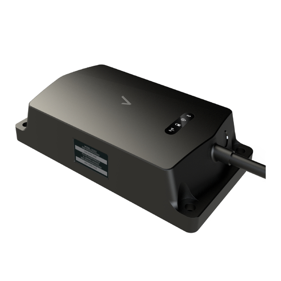
Identifying the EAT device
How to replace EAT battery pack
Advertisement
Table of Contents

Subscribe to Our Youtube Channel
Related Manuals for Verizon AI-111


Summary of Contents for Verizon AI-111
- Page 1 Wiring the device • Mounting the device Product overview The Equipment Asset Tracker (EAT) is designed by Verizon Connect and replaces the CalAmp TTU- 2830. The EAT device offers: • I/O leads 2 Digital inputs for sensors such as boom and PTO 1 digital output capable of triggering a relay •...
-
Page 2: Device Label
Before getting started, be aware that there are two Verizon Connect devices that look alike, EAT and EAT-B. This installation guide deals with the EAT device. The EAT device is powered by the equipment, that is, the asset, and therefore has a power cable attached to it. -
Page 3: Status Button
Status button • For a new device out of the box or a device that has had the battery replaced, the status button turns the device on. For a new device, press the button twice: First to power on, then press it again to light the LEDs and connect to network. - Page 4 Status LEDs The device runs a status test for Battery, Network, and GPS whenever the status button is pressed. Status test results are displayed on the status LEDs as described below. The LEDs stay lit only for a brief duration. However, the test can be repeated by pressing the status button again, which is useful for determining the best place on the asset to mount the device.
- Page 5 I C O N N A M E S T A T U S Bluetooth At this time, the device does not support any Bluetooth featu further notice. What to bring • Cordless drill with metric and standard bits. For mounting hardware sizes, see What's in the box.
-
Page 6: What's In The Box
What's in the box • EAT Device with attached 15’ harness 4 x self-drilling screws for metal: standard 5/16” hex head, number 12 size, 1 inch long • • 4 x bolts: Serrated-flange 5/16” hex head, 10-32 thread, 1 ¼ inch long, .19 inch screw width 4 x locknuts 3/8”... - Page 7 Reveal Hardware Installer App The Reveal Hardware Installer App replaces the VZ Check App. Download the Reveal Hardware Installer app from either Google Play Reveal Hardware Installer for Android or the App Store Reveal Hardware Installer for iOS. Using the Reveal Hardware Installer App, prior to mounting the device on the asset, you will: 1.
- Page 8 2. Select Multi PWRD Asset Devices from the list. (Note that the selection applies to all asset trackers, for powered or non-powered assets.) 3. Test the device for network connectivity and GPS location fix. (See sections on Status Button Status LEDs).
- Page 9 4. Select the wiring method (2-wire or 3-wire). (See Wiring the device.) 5. Enter the asset information. 6. Wire and mount the device to the asset. (See sections on Wiring the device Mounting the device.) After wiring, but before mounting, press the status button again to confirm the Network and...
-
Page 10: Wiring The Device
GPS LEDs light up when the device is wired to the asset. 7. Complete device setup and activation. Wiring the device This section covers the following topics:... - Page 11 • Device harness wiring layout • Wiring best practices • Wire splicing • 2-wire versus 3-wire installation • 2-wire installation steps • 2-wire installation for nose-mounted semi-trailers using a 7-way connector • 3-wire installation steps • 3-wire Installation for reefer trailers •...
- Page 12 • The ground wire is actually three ground wires joined together at the exposed end, giving the appearance of being one wire. About the sensor wiring connections (digital inputs) The EAT device is capable of sensing voltage transitions of at least 6 volts on 12/24 volt systems and requires 3mA current when voltage is present in the on phase.
-
Page 13: Wiring Best Practices
Wiring Best Practices To prevent chafing, run the harness cable through a pass-through hole, using existing holes to pass the cable through rather than drilling a new one. If drilling is necessary, always check before you drill to verify you are not drilling into anything unintended behind the drilling surface. Insert a grommet, that is the right size and type for the hole, into the newly drilled hole to protect the wire and seal with all-weather silicone as necessary. -
Page 14: Wire Splicing
In addition, create a drip loop to prevent moisture from running down the length of the wire toward devices and connections. Wire splicing If for some reason using butt connectors and ring connectors is not practical, and if wires will not be exposed to the elements (for example, wires lying internally within the asset’s cab) any splicing should be done by using the standard “poke and wrap”... - Page 15 5. Apply two wire ties to the splice. The first goes over the splice and the other approximately one inch down the line of splice. 2-wire versus 3-wire installation Determine whether you are doing a 2-wire or 3-wire installation. The Reveal Hardware Installer app will ask you to select one or the other.
- Page 16 9. Connect the device’s red VDC power wire to the trailer’s blue “aux” wire/center pin on the 7-way trailer wire stud using a heat shrink ring terminal poke-and-wrap method. Alternatively, the marker or running lights wire can be used instead of the aux wire. Shown below are the typical wiring colors and pin layout for a tractor-trailer 7-way connector.
-
Page 17: Mounting The Device
As shown in the the EAT device has these I/O options: device harness wiring layout, • Two digital inputs. These inputs can switch between either positive or negative polarity, so no relays are required. As shown in the Device Harness Wiring Layout section, each of the two inputs has two wire leads, for high (positive) and low (negative). - Page 18 This section provides information about device and where to mount the how to mount Where to mount the device Where the device is mounted depends partly on the type of asset, but the device’s long harness enables a variety of options. The most important thing to remember is to first hold the device where you intend to mount it and test for Network and GPS before you start drilling holes.
- Page 19 After a successful Network and GPS test, and after completing the device setup and activation in the Reveal Hardware Installer app. 1. Hold the device where it will be mounted mark the positions of the four mounting holes where you will drill.
Need help?
Do you have a question about the AI-111 and is the answer not in the manual?
Questions and answers