Advertisement
Quick Links
Advertisement

Summary of Contents for Multitek MultiLed M812-LD Series
- Page 1 MULTILED M812-LD* OPERATING MANUAL...
- Page 2 4. PROGRAMMING PARAMETERS 5. RS485 COMMUNICATION 6. INSTALLATION 7. CONNECTION DIAGRAMS 8. SPECIFICATION Revision 4 Date 21-10-2011 Multitek Ltd. Lancaster Way, Earls Colne Business Park, Earls Colne, Colchester, Essex. U.K. Tel 01787 223228 Fax 01787 223607 Email : Support@multitek.ltd.uk www.multitek-ltd.com...
- Page 3 Version 4 update: Page 53: Changed 3X Modbus registers to odd numbers. Page 57: Changed 4X Modbus registers to odd numbers.
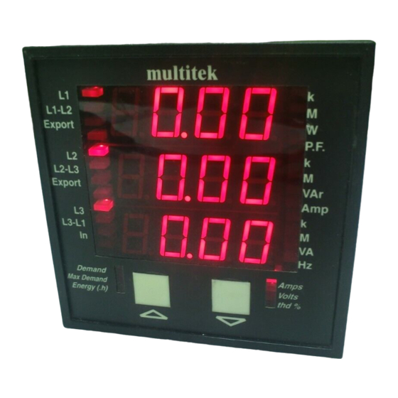
- Page 4 1.1 General The MultiLed M812-LD* is a compact 96 x 96 mm Din case 3 phase power meter, with the ability to measure Volts, Amps, Frequency, Active Power, Reactive Power, Apparent Power, Active Energy, Reactive Energy, Power Factor, Average Demand Amps, Active Power Apparent Power, Maximum Demand Amps, Active Power and Apparent Power Power Systems :- Single Phase, Single Phase 3 wire, 3 Phase 3...
- Page 5 1.3 Relay Output The option of a relay is provide on M812 models. The relay output provides a pulse output corresponding to either Watt hour or VAr hour consumption. (see programming section 4.3.1). The MultiLed automatically calculates the pulse rate and whether the units are W.h, kW.h or MW.h (VAr.h, kVAr.h or MVAr.h) from the nominal voltage and current inputs.
- Page 6 2.0 MultiLed Models M812-LD* measures and displays phase and line volts, phase amps, frequency, active power, apparent power, reactive power, active energy, reactive energy, power factor, average demand for amps active power and apparent power, maximum demand for amps, active power and apparent power and option of neutral current.
- Page 7 3. DISPLAY SCREENS 3.1 . The sequence of the parameters displayed are dependant on the model and the wiring system that MultiLed is programmed for. 3.1.1 The following screens appear on M812-LD9 3 phase 4 wire unbalanced load :- ACTION : Switch on power COMMENTS : The MultiLed is programmed to 3 phase...
- Page 8 ACTION : Press COMMENTS : The third screen shows 3 phase current L1, L2, L3. If the button is pressed the MultiLed goes back to the previous screen. ACTION : Press COMMENTS : The fourth screen shows total Watt, VAr and VA of the 3 phase system.
- Page 9 ACTION : Press COMMENTS : If the option of neutral current is not ordered the fifth screen shows system Power Factor and Hz. Note minus sign and export annunciator indicate which quadrant the power and PF are in. See section 3.3.3. ACTION : Press COMMENTS :...
- Page 10 ACTION : Press COMMENTS : The eighth screen shows the Average Demand for Watts, Amps and VA, of the system being measured. ACTION : Press COMMENTS : The ninth screen shows the Maximum Demand (Peak Demand) for Watts, Amps and VA, of the system being measured.
- Page 11 ACTION : Press COMMENTS : The eleventh screen shows harmonic distortion of each phase current. ACTION : 10.0 Press COMMENTS : Pressing returns MultiLed to the previous screen. 3.1.2 3 phase 3 wire unbalanced load screen sequence. For 3 ph 3 w systems the screen sequence is identical to the 3 phase 4 wire unbalanced load, apart from the first screen where the voltage shown is the line to line voltage.
- Page 12 3.3 If the input measuring voltage and current signals are lost but the auxiliary supply is still present the MultiLed indicates this by displaying the following. COMMENTS : ---- This indicates that measuring signals are ---- not present but MultiLed is still functioning correctly.
- Page 13 3.3 Export Watt and Var measurements The MultiLed displays Export Watt and VAr readings by the corresponding Export annunciator led illuminating. If export annunciators are not illuminated Watt and VAr readings are importing. 3.4 Leading and Lagging Power Factor ( Capacitive and Inductive loads). 3.4.1 Leading Power Factor.
- Page 14 3.4.4 Quadrant / Power Diagram 360° 0° IMPORT WATTS P.F. P.F. = - 270° 90° EXPORT WATTS P.F. = E P.F. = E- EXPORT IMPORT VArs 180° VArs Note the E in the above diagram signifies that the Export LED annunciator is illuminated 3.4.5 Examples of Import and Export Power.
- Page 15 3.4.5.2 Power factor at 0.5 lead (120 deg) negative quadrant. Line 1 = Exporting kW Line 2 = Exporting kVAr Line 3 = VA measurement 3.4.5.3 Power Factor at 0.5 lag (240 deg) negative quadrant. Line 1 = Exporting kW Line 2 = Importing KVAr Line 3 = VA measurement 3.4.5.4 Power Factor at 0.5 lag (300...
- Page 16 3.4.6 Examples of Import and Export Lag and Lead Power Factors. 3.4.6.1 Power Factor at 0.5 lead (60 deg) Line 1 = Leading Power Factor (capacitive load) in positive quadrant Line 3 = Frequency measurment. 3.4.5.2 Power factor at 0.5 lead (120 deg) negative quadrant. Line 1 = Leading Power Factor (capacitive load) in negative quadrant Line 3 = Frequency measurment.
- Page 17 3.4.5.3 Power Factor at 0.5 lag (240 deg) negative quadrant. Line 1 = Lagging Power Factor (inductive load) in negative quadrant Line 3 = Frequency measurment. 3.4.5.4 Power Factor at 0.5 lag (300 deg) positive quadrant. Line 1 = Lagging Power Factor (inductive load) in positive quadrant Line 3 = Frequency measurment.
- Page 18 4. PROGRAMMING All units are fully programmed by the factory but there are many features that can be programmed by the User to suit individual applications and needs. Programmed values and parameters are stored in non volatile memory and are therefore retained in power down situations. 4.1 To enter the programming mode the two front buttons &...
- Page 19 ACTION : code Press & simultaneously, and hold for 5 seconds. o000 COMMENTS : MultiLed is now is now asking for the 4 digit security code. ACTION : code Press 2000 COMMENTS : Press until 1st digit of the security code figure is shown.
- Page 20 ACTION : code Press 2400 COMMENTS : Press until 2nd digit of the security code figure is shown, in this example when 4 is shown. ACTION : code Press 2400 COMMENTS : Press cursor moves to the 3rd digit. ACTION : code Press 2410...
- Page 21 ACTION : code Press 2410 COMMENTS : Press cursor moves to the 4th digit. ACTION : code Press 2413 COMMENTS : Press until 4th digit of the security code figure is shown, in this example when 3 is shown. ACTION : Press level required is shown.
- Page 22 4.2.1 Adjusting Display Brightness. ACTION : Press & simultaneously, and hold for 5 seconds COMMENTS : MultiLed is now in LED brightness adjustment mode ACTION : Press COMMENTS : Screen shows brightness level 2. Pressing scrolls through 0,1,2,3,4 Note the factory sets brightness level at 2.
- Page 23 4.2 Programming of nominal voltage, current inputs and ratios. The SYS (system) mode allows the user to program the nominal voltage & current inputs and ratios. Please note the ratios can be changed as long as the secondary (the input to the MultiLed) stays as shown on the data label which is on the side of the product.
- Page 24 ACTION : 230.0 Press COMMENTS : Display shows nominal voltage programmed by the factory. In this example 230 volts L.N. The cursor flashes under the 1 st digit. To change from 230 volts to for example 11kV :- ACTION : 230.0 Press COMMENTS :...
- Page 25 ACTION : 010.0 Press COMMENTS : Press and scroll until 2nd digit shows 1. ACTION : 010.0 Press COMMENTS : Cursor moves to 3rd digit. ACTION : 011.0 Press COMMENTS : Press and scroll until 3rd digit shows...
- Page 26 ACTION : 011.0 Press COMMENTS : Cursor moves to the 4th digit. In this example the 4th is 0 so do not alter. ACTION : 011.0 Press COMMENTS : sele SELE message appears, now unit can be set for V, kV or MV. (In this example, unit was set for 230V therefore annunciator remains unlit).
- Page 27 ACTION : 011.0 Press sele COMMENTS : Press if input required is kV. i.e. The k annunciator on right hand side is illuminated. ACTION : 011.0 011.0 Press sele COMMENTS : Press if input required is MV. The M annunciator is illuminated.
- Page 28 4.2.2 Programming current inputs. Once the voltage input has been set and is pressed the screen goes to the current setting. ACTION : 100.0 Press COMMENTS : This shows the input set for 100 Amp input. The cursor flashes under the 1st digit.
- Page 29 ACTION : Press 200.0 COMMENTS : The cursor moves to the 2nd digit. ACTION : 250.0 Press COMMENTS : Continue pressing until the 2nd digit shows 5. ACTION : 250.0 Press COMMENTS : The cursor will move to the 3rd digit. In this example the 3rd and 4th digits require 0 so press twice to move the...
- Page 30 ACTION : 250.0 Press COMMENTS : sele SELE message appears, now unit can be set for A or kA, MA. (In this example unit was set for 250A therefore annuciator remains unlit). Pressing scrolls through A, kA, MA i.e. k or M annuciator is lit.
- Page 31 ACTION : 250.0 Press sele COMMENTS : Press if input required is MA. The M annunciator is illuminated. ACTION : Press COMMENTS : This indicates that the nominal voltage and current have been programmed. NOTE: If either CT ratio or VT ratio is change the MultiLed automatically resets the energy and demand registers to zero.
- Page 32 4.3 Programming relay output. The RELAY programming mode allows the User to assign the relay pulsed output to either Watt hour or VAr hour. The MultiLed automatically calculates the pulse per hour from the nominal V & I input values and will also calculate whether they are W.h, kW.h or MW.h Additionally there is the facility to change the pulse rates in multiples of 10 and the pulse width between 20 msec and 200 msec in multiples of 20 msec.
- Page 33 ACTION : 825.0 Press sele COMMENTS : Press if pulse output required is W.h (The MultiLed will automatically select whether to use W.h, kW.h or MW.h and illuminate the corresponding annunciator) ACTION : 825.0 Press sele COMMENTS : Press if pulse output required is VAr.h (The MultiLed will automatically select whether to use VAr.h kVAr.h or MVAr.h and annunciator will illuminate)
- Page 34 ACTION : 825.0 Press sele COMMENTS : Press activates the decimal point. So with decimal point in this position divisor is set to 1 (825.0). So every count MultiLed registers and stores the relay pulses. ACTION : 82.50 Press sele COMMENTS : Pressing scrolls the decimal point.
- Page 35 4.3.3 Setting pulse width. ACTION : Press 0.100 COMMENTS : puls The MultiLed is now in the pulse width LEN (LENGTH) setting mode. Pulse widths can be set between 20 msec and RS485 200 msec. In this example the pulse width is set at 100 msec.
- Page 36 4.4 RS485 data output port setting. (RS485 or RS232 are options if this option has not been purchased move to section 4.5) 4.4.1 Setting Baud Rates ACTION : Press three times COMMENTS : The MultiLed is now in the RS 485 port setting mode.
- Page 37 4.4.2 Setting Parity ACTION : prty Press COMMENTS : The MultiLed is now in the parity setting mode. The n= NO parity. Pressing scrolls through the options n, E = even, O= odd. Press if NO parity is required. 4.4.3 Setting Stop Bits and Addresses. if the MultiLed communication port is RS232 proceed to 4.4.4.
- Page 38 4.4.5 Setting the Node Address (RS485 only) The number of node addresses available is 1 to 247. Each individual MultiLed that is to be connected to a common bus must have its own unique node address. ACTION : Press 0001 COMMENTS : The MultiLed is now in the node addr...
- Page 39 Example to set node address to 181 :- ACTION : 0101 Press COMMENTS : addr Press until the 2nd digit shows 1. ACTION : Press 0101 COMMENTS : addr The cursor now moves to the 3rd digit. 0181 ACTION : Press addr COMMENTS :...
- Page 40 ACTION : Press 0181 COMMENTS : addr The cursor now moves to the 4th digit. As the 4th digit in this example is 1 as required press The address 181 is now programmed. ACTION : Press COMMENTS : This indicates that the address is programmed.
- Page 41 ACTION : nrgy Press 4 times. COMMENTS : The MultiLed is now in the energy register reset mode. ACTION : rest Press nrgy COMMENTS : The screen now display's the option to either reset energy register (Y) yes or do not reset energy registers (N) no.
- Page 42 MultiLed takes the average of mins. 2 to 16 and displays the result. ACTION : Press 5 times COMMENTS : The MultiLed is now in the demand time period setting mode. ACTION : Press COMMENTS : The MultiLed is now in the time period setting mode.
- Page 43 ACTION : Press COMMENTS :Indicates that demand time period has been set. Note when a time period has been set the MultiLed automatically resets the time to zero. The new time period starts once MultiLed is returned to the measuring mode. 4.6.1 To reset demand time period to zero.
- Page 44 ACTION : Press COMMENTS : Indicates that demand time period has been reset to zero. Demand period will start when MultiLed is returned to measuring mode. NOTE. The Maximum Demand values are the maximum values the MultiLed has measured from the time meter is switched on. These maximum demand values are displayed until either auxiliary is switch off, demand is reset to zero or demand time is altered.
- Page 45 ACTION : Press 0000 COMMENTS : Four zero are displayed and the cusor is flashing under the first digit. Using scroll through 0-9 until first digit of code required is shown. Example to program 1605. ACTION : Press 1000 COMMENTS : Press until desired figure is shown in this example 1.
- Page 46 ACTION : Press 1600 COMMENTS : Press until desired figure is shown, in this example 6. ACTION : Press 1600 COMMENTS : Press cursor moves to the 3nd digit. In the example the third digit required is 0 so press again.
- Page 47 ACTION : Press 1605 COMMENTS : Press until desired figure is shown in this example 1. ACTION : Press COMMENTS : Indicates that security code is programmed. 4.8 To terminate programming for M812-LD units. Once the programming has been completed there are two options available either to cancel (CNCL) all data entered whilst in the programming mode or to end (END) programming and return to measuring function.
- Page 48 ACTION : cncl Press 7 times COMMENTS : The MultiLed is now in the CANCEL mode. Press to cancel all data entered during programming and return to measuring function. Press to go to END function. ACTION : Press COMMENTS : All the information entered whilst in the programming mode has been cancelled and the MultiLed has returned to the...
- Page 49 ACTION : Press 8 times COMMENTS : Press to end programming, but before programming is ended you will be asked if you wish to retain the security code. ACTION : pass Press COMMENTS : code The screen now display's the option to either retain security code (Y) yes or cancel security code (N) no.
- Page 50 5.0 RS485 COMMUNICATION The RS 485 allows remote reading and programming of the MultiLed via a host computer. The communication protocol used is a subset of Modicons Modbus, enabling the use of standard host computer, PLC and scada programs. Up to 32 MultiLeds can be connected in parallel to a single communication bus 5.1 MultiLed Modbus Protocol 5.1.1 Physical Connections...
- Page 51 Low level character format : With Odd or Even parity = 1 start bit, 8 data bits, 1 parity bit, 1 stop bit With NO parity = 1 start bit , 8 data bits, 2 stops bits. 5.1.3 Modbus Format Data format : 32 bit, floating point format to IEEE-754 standard, exponent bias 127, most significant byte transmitted first.
- Page 52 register 1 = start address 0 register 2 = start address 2 register 3 = start address 4 register 4 = start address 6 This also applies to the number of registers requested. If 2 registers are requested the number of WORDS in the packet's [Number of registers] slot should equal 4.
- Page 53 5.3.6 Timing RTU frame timing : The message start with an interval of at least 3.5 character times. Following the last transmitted character, a similar interval of a least 3.5 character times marks the end message. The entire message frame must be transmitted as a continuous stream.
- Page 54 Function 4 (04 hex) - read input registers. (3X) These registers contain the measured and calculated values of the instrument. Register addresses in the instrument start at 0 but in keeping with Modicon Modbus codes, are designated addresses starting at 30001. Packet from master format : [Node Addr][04][reg start addr(2 bytes)][No.
- Page 55 System W 30019 0012 All Types System VA 30021 0014 All Types System VAr 30023 0016 All Types System P.F. 30025 0018 All Types System W.h ** 30027 001A All Types System VAr.h ** 30029 001C All Types System Frequency 30031 001E All types Watts L1...
- Page 56 * In 3 wire mode system V1, V2, V3 will have the same value as volts L2-L1, L3-L2, L1-L3. Example To obtain all 3 line powers in a 4 wire system on Node 23h Packet from master : tart at Power L1 (0020), request 3 regs (0006 words) [23][04][0020][0006][CRC(2bytes)] Response from slave format : [23][04][OC][12 bytes of data(3 regs x 4 bytes)][CRC(2 bytes)]...
- Page 57 Function 16 (10 hex) - Preset Multiple registers (4X) These registers contain the system settings and controls. Register addresses in the MultiLed at 0, but in keeping with Modicon Modbus codes, are designated addresses starting 40001. Write Packet from master : [Node addr][10][Register start address(2 bytes)][No of registers(2 bytes)][Byte count][Data (byte count bytes)][CRC (2 bytes)] Response from slave format :...
- Page 58 4X REGS Modbus Reg Start Read (code 3) Write (code 16) Name Addr. Addr. (dec) (hex) Sys. V 40001 0000 Get the system Set the system voltage voltage Sys. I 40003 0002 Get the system Set the system current current Sys.
- Page 59 Reset 40017 0010 Illegal operation Initialise energy energy counters Write 0 counters to this register Reset 40019 0012 Illegal operation Initialise energy demand counters Write 0 counters to this register Example. To obtain System Volts & System Amps on Node 23h Packet from master format : Start at system voltage (0000), request 2 regs (0004 words) [23][03][0000][0004][CRC(2 bytes)]...
- Page 60 Response from slave format : [23][11][28][40 bytes of data (10 regs x 4 bytes)][CRC(2 bytes)] The table on the next page lists the various names, their register position in the data portion of the return packet and their usage. Report Slave ID Register Packet Position Name...
- Page 61 6. INSTALLATION 6.1 Case The MultiLed M812-LD* is designed for panel mounting and uses a standard 96 x 96 DIN case. CASE DIMENSIONS PANEL CUTOUT 92 mm FRONT 96 mm (+ 0.8 mm) 92 mm (+ 0.8 mm) 96 mm SIDE 94 mm 6 mm...
- Page 62 6.2 Auxiliary Supply The auxiliary supply can be connected in parallel with the measuring input voltage, but this restricts the measuring range of the input voltage to ± 15% of nominal. 6.3 Protective Fuses It is good practice for the user to provide fuse protection to all input circuits and the auxiliary supply.
- Page 63 6.5 Voltage Transformers (V.T.s) Connection of voltages higher than the rated voltage, that is specified on the MultiLed data label, is possible using external V.Ts. These transformers must be at least Class1 accuracy. The secondary of these transformers must have the same nominal voltage as that specified on the data label on the MultiLed.
- Page 64 7. CONNECTION DIAGRAMS 7.1 All connections must be made as shown ensuring, all starts and finishes of current and voltage transformers are connected as shown. Wiring Reference Note : k = x1 (white) l = x2 (black) K=H1, L=H2 SINGLE PHASE SINGLE PHASE 3 WIRE...
- Page 65 3 PHASE 3 WIRE UNBALANCED LOAD 3 PHASE 4 WIRE UNBALANCED LOAD...
- Page 66 SYSTEMS MULTILED M812-LD* Single phase PARAMETERS DISPLAYED Single phase 3 Wire Phase and Line Volts 3 phase 3 wire unbalanced Phase Amps 3 phase 4 wire unbalanced Frequency AUXILIARY Active Power AC voltage 115 or 230 volts (± 15%) Apparent Power 45 to 65 Hz burden <...
- Page 67 INPUT Surge withstand: Rated Un 57.8 to 600V specify IEC 801 / EN55020 nominal voltage. ANSI C37.90A Interference: Range 20-120% Un EHF 2.5 kV 1MHz complying Burden 0.5VA per phase with IEC 255-4 Overload 1.5 x Un continuous Protection ClassII : 4 x Un for 1 second complying with IEC348 / BS4753 Rated In...
- Page 68 UL, C-UL, CSA ENCLOSURE Std. DIN case 96 x 96 x 98mm Panel mount Via 4 retaining brackets Cutout 92 + 0.8mm x 92 + 0.8mm Material Black Polycarbonate complying with UL 94 VO Terminals Screws for 2 x 0.5-5mm Weight 0.8kg / 1.75lb OUTPUT RELAY...
Need help?
Do you have a question about the MultiLed M812-LD Series and is the answer not in the manual?
Questions and answers