Advertisement
PRO PM335 Quick Start Manual
This guide instructs the user on installation, wiring, configuring and operating the PM335
multi-meter. This guide does not substitute the full user manual or the detailed safety
instructions. to download the manual and other related material, please visit our website:
www.satec-global.com
Warning! Only a licensed electrician may perform installations and wiring of the
PM335.
INSTALLATION
The PM335 is designed for 4-inch round / 92x92mm square panel mounting.
Please note to leave room for future expansion: when a basic units (no modules), it is
recommended to maintain a minimal gap of 30-100mm to the right (when facing front panel)
of the unit, allowing future installation of additional detachable SATEC modules (depending on
number of added modules: 17.8mm each).
BG0635 REV.A1 ENGLISH
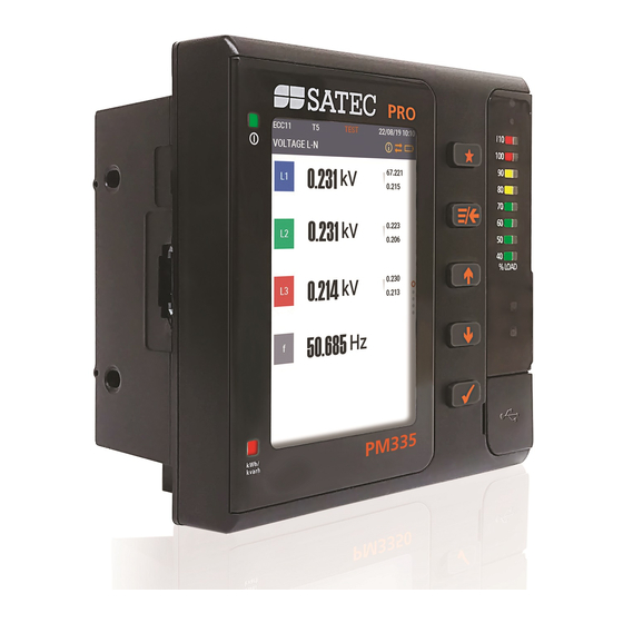
Figure 1: PM335 front panel
PRO PM335 Quickstart
www.satec-global.com
Advertisement
Table of Contents

Subscribe to Our Youtube Channel
Related Manuals for Satec PRO PM335


Summary of Contents for Satec PRO PM335
- Page 1 Please note to leave room for future expansion: when a basic units (no modules), it is recommended to maintain a minimal gap of 30-100mm to the right (when facing front panel) of the unit, allowing future installation of additional detachable SATEC modules (depending on number of added modules: 17.8mm each).
- Page 2 (colors vary according to the CT model) wire to the "-" terminal. Connect the voltage measurement inputs (22-12 AWG; bottom-center of rear end). Connect the com wire (26-12 AWG, shielded) to COM1 (RS485, top-left of rear-end). Power-on the unit. Figure 2: Electrical wiring PRO PM335 QuickStart www.satec-global.com...
- Page 3 BASIC CONFIGURATION AND OPERATION The PRO PM335 is operated via the LCD display, 2 LEDs and 4 pushbuttons (figure 1: front panel). When powered on, the device will default to displaying voltages, for basic setup back up (<- button) to the home screen navigate with arrows to “setup” (select with ), enter default password (“9”) and select (“apply”).
- Page 4 Default current mode (HACS model): Alternating Current (AC) Default serial com settings (RS485): 19,200 Baudrate; address = 1 For convenient configuration please use SATEC’s PAS engineering software, connecting your PC to the USB port (type C) at the right side of the front panel To download PAS (free): www.satec-global.com/power-analysis-software...
Need help?
Do you have a question about the PRO PM335 and is the answer not in the manual?
Questions and answers