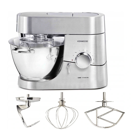
Kenwood KM001 Assemble & Disassembling
Hide thumbs
Also See for KM001:
- User manual (153 pages) ,
- Instructions manual (43 pages) ,
- Manual (43 pages)
Advertisement
Quick Links
Spares - KM001/002/003/502/005/006/007/506 Disassembly & re-assembly instructio...
DISMANTLING AND RE-ASSEMBLING OF SOVEREIGN - KM001/002/003 AND
KM005/006/007
Please pick one of the following:
TOP COVER
PEDESTAL
TOP COVER
1.
REMOVE ALL COVERS
2.
REMOVE 4 SCREWS AND SPIGOTS
(NO.2 POZIDRIVE)
3.
REMOVE SPIGOT PLATE
(A SMALL FLAT BLADED SCREWDRIVER
INSERTED BETWEEN THE PLATE AND THE
CASTING CAN BE USED TO EASE OFF THE
PLATE AROUND THE HIGH SPEED SPIGOT)
http://www.kenwoodservice.co.uk/product-files-kar/sovereign-tech2.htm
MOTOR
GEARBOX
Page 1 of 11
LATCH ASSEMBLY
SPEED CONTROL KNOB
30/04/2009
Advertisement

Summary of Contents for Kenwood KM001
- Page 1 Spares - KM001/002/003/502/005/006/007/506 Disassembly & re-assembly instructio... Page 1 of 11 DISMANTLING AND RE-ASSEMBLING OF SOVEREIGN - KM001/002/003 AND KM005/006/007 Please pick one of the following: TOP COVER MOTOR LATCH ASSEMBLY PEDESTAL GEARBOX SPEED CONTROL KNOB TOP COVER REMOVE ALL COVERS REMOVE 4 SCREWS AND SPIGOTS (NO.2 POZIDRIVE)
- Page 2 Spares - KM001/002/003/502/005/006/007/506 Disassembly & re-assembly instructio... Page 2 of 11 REMOVE 3 SCREWS (NO.2 POZIDRIVE) RAISE HEAD REMOVE 2 SCREWS (TX15) LOWER HEAD LIFT OFF TOP COVER FROM HIGH SPEED OUTLET END OF CASTING http://www.kenwoodservice.co.uk/product-files-kar/sovereign-tech2.htm 30/04/2009...
- Page 3 Spares - KM001/002/003/502/005/006/007/506 Disassembly & re-assembly instructio... Page 3 of 11 RE-ASSEMBLY IS THE REVERSE OF STEPS 1-8 EXCEPT TAKE CARE TO AVOID DISTURBING ANTI-VIBRATION CAP ON THE GEARBOX. Click here to return to the top of the page. PEDESTAL REMOVE ALL COVERS http://www.kenwoodservice.co.uk/product-files-kar/sovereign-tech2.htm...
- Page 4 Spares - KM001/002/003/502/005/006/007/506 Disassembly & re-assembly instructio... Page 4 of 11 INVERT THE APPLIANCE REMOVE 2 STUFFER BOX SCREWS (TX15 OR TX20) UNCLIP AND REMOVE LID REMOVE 2 FIXING SCREWS (TX20) REMOVE BOX (HANDY AS SCREW TRAY AT THIS POINT)
- Page 5 Spares - KM001/002/003/502/005/006/007/506 Disassembly & re-assembly instructio... Page 5 of 11 CAREFULLY OPERATE THE HEAD RELEASE WHILE RESTRAINING THE PEDESTAL. ALLOW TO FULLY OPEN SLOWLY. WARNING: THE PEDESTAL WILL SPRING UP VIOLENTLY UNLESS IT IS RESTRAINED REMOVE 4 SCREWS (TX20)
- Page 6 Spares - KM001/002/003/502/005/006/007/506 Disassembly & re-assembly instructio... Page 6 of 11 HINGE PIN PUSHES OUT IF REQUIRED (RETAINED BY VENT PANEL IN BODY) RE-ASSEMBLY IS THE REVERSE OF STEPS 1-14 EXCEPT TAKE CARE THAT THE POWER SUPPLY CABLE DOES NOT RUB...
- Page 7 Spares - KM001/002/003/502/005/006/007/506 Disassembly & re-assembly instructio... Page 7 of 11 REMOVE BELT PLACING THE TOP COVER IN POSITION AT THIS STAGE STABILIZES THE APPLIANCE WHEN INVERTED STRIP DOWN PEDESTAL AS FAR AS STEP 14. REMOVE QUADRANT COVER REMOVE SINGLE VENT PANEL SCREW...
- Page 8 Spares - KM001/002/003/502/005/006/007/506 Disassembly & re-assembly instructio... Page 8 of 11 UNLATCH SPRING REMOVE TAG REMOVE BRUSH REASSEMBLE IN REVERSE ORDER Click here to return to the top of the page. GEARBOX Dismantling the gearbox involves removal of the large pulley.
-
Page 9: Latch Assembly
Spares - KM001/002/003/502/005/006/007/506 Disassembly & re-assembly instructio... Page 9 of 11 Use a mincer. Attach the mincer and position a screwdriver between the cutter blades and close to the scroll to stop it rotating. Please note, it is advisable to use the coarse screen as this allows room for a larger diameter screwdriver. -
Page 10: Speed Control Knob
Spares - KM001/002/003/502/005/006/007/506 Disassembly & re-assembly instruc... Page 10 of 11 INVERT THE APPLIANCE CAREFULLY OPERATE THE HEAD RELEASE WHILE RESTRAINING THE PEDESTAL. ALLOW TO FULLY OPEN SLOWLY WARNING: THE PEDESTAL WILL SPRING UP VIOLENTLY UNLESS IT IS RESTRAINED! UNHOOK LATCH SPRINGS... - Page 11 Spares - KM001/002/003/502/005/006/007/506 Disassembly & re-assembly instruc... Page 11 of 11 LIFT OUT CONTROL BOARD AND INSULATION SHEET REMOVE SINGLE SCREW (NO.1 POZIDRIVE) RE-ASSEMBLE IN REVERSE ORDER Click here to return to the top of the page. http://www.kenwoodservice.co.uk/product-files-kar/sovereign-tech2.htm 30/04/2009...


Need help?
Do you have a question about the KM001 and is the answer not in the manual?
Questions and answers
Hi how do I get the pin out so I can replace the warn part (attachment for the liquidizer
To remove the pin to replace the worn attachment for the Kenwood KM001 liquidizer:
1. Remove the top cover.
2. Remove the top washer.
3. Remove the 3 motor screws (No.2 Pozidrive).
4. Remove the belt.
5. Locate and push out the hinge pin if required. It is retained by the vent panel in the body.
This allows disassembly to access and replace attachments. Reassembly is the reverse of disassembly steps.
This answer is automatically generated
Hi there thank you for your response I appreciate it. IT SEEMS THAT THE PIN IS STUCK I HAVE TRIED ALL METHODS TO TRY AND REMOVE IT WITH NO LUCK .IS THERR A SPECIAL TOOL I COULD PURCHASE? I HAVE TRIED TAPPING IT OUT BUT DOES NOT BUDGE AT ALL . I APPRECIATE YOUR HELP AND ASSISTANCE. REGARDS ROB