Table of Contents
Advertisement
Advertisement
Table of Contents

Subscribe to Our Youtube Channel
Related Manuals for Ametek Jofra DTI-1000 A


Summary of Contents for Ametek Jofra DTI-1000 A
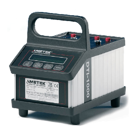
- Page 1 Reference manual Digital Temperatur Indicator Jofra DTI-1000 A/B...
- Page 2 Reference Manual Digital Temperature Indicator JOFRA DTI-1000 A/B © Copyright 2005 AMETEK Denmark A/S...
- Page 3 The structure of the manual This reference manual is aimed at users who are familiar with AMETEK calibrators, as well as those who are not. The manual is divided into 8 chapters, which describe how to set up, operate, service and maintain the indicator. The technical specifications are described as well.
-
Page 4: Table Of Contents
List of contents General information ........... 4 Warranty ..............5 Safety instructions ............. 6 Introduction ..............8 Functionality ............... 9 Functional description ..........11 Indicators ..............12 Touch pad ..............12 Connections.............. 13 Operation ..............15 Operating area ............15 Connection of sensors .......... -
Page 5: General Information
General information Congratulations on your new JOFRA DTI-1000! With the AMETEK indicator, you have chosen an extremely effective instrument which we hope will live up to all your expectations. Over the past many years, we have acquired extensive knowledge of industrial temperature calibration. -
Page 6: Warranty
This instrument is warranted against defects in workmanship, material and design for two (2) years from date of delivery to the extent that AMETEK will, at its sole option, repair or replace the instrument or any part thereof which is defective, provided, however, that this warranty shall not apply to instruments subjected to tampering or, abuse, or exposed to highly corrosive conditions. -
Page 7: Safety Instructions
Safety instructions Read this manual carefully before using the instrument! Please follow the instructions and procedures described in this manual. They are designed to allow you to get the most out of your DTI system and avoid any personal injuries and/or damage to the instrument. Disposal –... - Page 8 Caution… When connecting the PC and the indicator please ensure that both the PC and the indicator are switched off at the mains. Failure to do so may result in your equipment being damaged. 124745 04 2017-08-10...
-
Page 9: Introduction
Introduction The DTI (Digital Temperature Indicator) system is designed for fast and traceable calibration. The system is portable. The DTI is prepared for re-calibration by your local calibration laboratories, and all necessary instructions for the re-calibration is stated in this manual. The DTI is a precision instrument and to achieve the precision, a set of sensor coefficients relating to the specific sensor must be present in the DTI. -
Page 10: Functionality
Functionality Overview: 124745 04 2017-08-10... - Page 11 Description Sensor 1 connections Sensor 1 connections Sensor 2 connections Sensor 2 connections Ground terminal for cable shields Display with 2 * 20 characters Soft keys RS232 connector Power inlet for mains adapter 2017-08-10 124745...
-
Page 12: Functional Description
The sensor coefficients can be inspected by the user and changed in the software program. The power supply is made by eight 1.5 Volt batteries or a mains adapter. Use only mains adapter supplied by AMETEK in order to comply with the requirements in EN50081-1 (1992) and EN50082-1 (1992). -
Page 13: Indicators
Indicators The DTI only uses the display for all indications. The display has 2*20 characters which will swap between read-out values or menu selection when requested. Please see section 5.2.1 to 5.2.7 for possible display read-outs. Please note that the error messages will also be showed in the display, see section 7.3. -
Page 14: Connections
Connections All signal cables have to be connected to the top plate (grounding on the back plate). Power and communication cables have to be connected on the back plate. Top plate connections SENSOR 1 SENSOR 2 Back plate connections 2 x 4 PCS BATTERIES TYPE AA 9VDC RS 232 200 mA... - Page 15 Ground terminal for shield on the signal cables. 9VDC Power input for mains adapter 9VDC 200mA. 200 mA Connector for RS232C interface. RS 232 2017-08-10 124745...
-
Page 16: Operation
Operation Operating area Both of the DTI models are intended for use in areas which meet the following: Temperature range 0°C to 50°C (32°F to 122°F) Humidity 0% to 90% Protection class IP20 Warning • The indicator must not be used for any purposes other than those described in this manual, as it might cause a hazard. -
Page 17: Connection Of Sensors
Connection of sensors The sensor should be connected to the terminals as shown in the figure below: Use the ground terminal (see the figure "Overview" section 4, pos. 3) for the cable shields in order to reduce noise. The connector type to extra connector on DTI-1000 is: LEMO FFA 1S 304 CNAC. -
Page 18: Power Supply
2 x 4 PCS BATTERIES TYPE AA 9VDC RS 232 200 mA Mains adapter It is also possible to supply the DTI from a mains adapter at the connector shown in the figure above. The mains adapter can be supplied by AMETEK. 124745 04 2017-08-10... -
Page 19: On / Off
5.2.2 On / Off Start the DTI by activating the softkey <ON/Off>. Following message will be shown in the display: SELF-CALIBRATION AND TESTING 1 This information states that the internal references and the sensor coefficients are checked. If the coefficients are incorrect an error message will occur which is described in section 7.3. -
Page 20: Reset
After this the input values will be shown in the display in the same format, as before the DTI was shut off last time: °C 23.65 °C 23.60 If there is no input signal or it is outside the measuring range a hyphen will be shown for that specific channel. - Page 21 Use the softkey <Reset/SELECT> to scroll between following types of units: UNIT SELECTION MENU READ-OUT MODE °C 23.65 °C UNIT: 23.60 °C │ °F 74.57 °F UNIT: 74.48 °F │ Ω 109.210 Ω UNIT: 109.191 Ω │ UNIT: 296.80 K 296.75 K Use the softkey <Menu/ENTER>...
-
Page 22: Resolution
5.2.5 Resolution In order to change the resolution on the read-out, you must press the softkey <MENU/Enter> 2 times. The following message will be shown in the display: RESOLUTION: 0.01 Use the softkey <Reset/SELECT> to scroll between following types of resolution: RESOLUTION SELECTION MENU READ-OUT MODE 23.65 °C... - Page 23 The sample period is dependent on the selected resolution which can be longer than sample rate to the display if a resolution above 0.1 is selected. The sample rates for the different resolutions are shown below: Resolution 0.01 0.001 Sample period 12 s Please note that read-out in Ω...
-
Page 24: Checking Sensor Coefficients
5.2.6 Checking sensor coefficients In order to check the sensor ID and coefficients on the DTI, press the softkey <MENU/Enter> 4 times. If Callendar van Dusen coefficients is used for the sensor, the following message will be shown in the display: SENSOR 1: 9402244 1.0000000E+02 Use the softkey <Reset/SELECT>... - Page 25 Use the softkey <Menu/ENTER> to leave this menu. The coefficients are used in the equations: ⋅ ⋅ ⋅ ⋅ R(t) 100) Below 0°C: ⋅ ⋅ ⋅ R(t) Above 0°C: If ITS-90 coefficients is used for the sensor, the following message will be shown in the display: CH1: 9402244...
- Page 26 CH1: 9402244 CH2: 9402245 RTPW: 1.0000000E+02 1.0000000E+02 │ │ CH1: 9402244 CH2: 9402245 aLR: 0.000000E-00 aLR: 0.000000E-00 │ │ CH1: 9402244 CH2: 9402245 bLR: 0.000000E-00 bLR: 0.000000E-00 │ │ CH1: 9402244 CH2: 9402244 cLR: 0.000000E-00 cLR: 0.000000E-00 │ │ CH1: 9402244 CH2: 9402245...
- Page 27 Use the softkey <Menu/ENTER> to leave this menu. Use the table below to convert ITS90 coefficient nomination to DTI- 1000 nomination. ITS90 Subrange a10 a11 2017-08-10 124745...
-
Page 28: Mode
5.2.7 Mode In order to change the reading, you must press the softkey <MODE> to scroll between following types of read-out: READ-OUT MODE 23.65 °C 23.60 °C DIFF (T1-T2) 0.05 °C 23.66 °C T1MAX. 23.64 °C T1MIN. 23.61 °C T2MAX. 23.59 °C T2MIN. -
Page 29: Technical Specifications
Technical specifications Electrical specifications Measuring input: 2 channels for 4 wire RTD sensors 0 to 360 Ω (-200 to 750°C / -328 to Measuring range DTI-1000 A 1382°F) 0 to 95 Ω (-200 to 750°C / -328 to Measuring range DTI-1000 B 1382°F) Accuracy DTI-1000 A ±6 ppm rdg + 1,4 mΩ... - Page 30 Mechanical specifications Electromagnetic Designed for use in controlled environment electromagnetic environment as defined EN61326-1 2013. Additional data - directives observed EN 61326-1: 2013: Electrical The following standards are equipment for measurement, control observed according to the EMC- and laboratory use – EMC Directive (2014/30/EU) requirements.
-
Page 31: Maintenance And Display Error Messages
Maintenance and display error messages Maintenance The DTI does not require specific maintenance before or after use. The user may carry out the following procedures himself. Cleaning surfaces Use alcohol or water and a soft cloth. Re-calibrate or change Use the software in order to re- coefficients for sensors calibrate/change the sensor coefficients (see section 8.0). -
Page 32: Display And Error Messages
Display and error messages If the DTI detects an error while running, it will automatically appear in the display. Following error messages can occur: Display message: Meaning/Action: Battery voltage low. BATTERY LOW Change batteries PRESS ANY KEY (section 7.2). No sensor connected to input or measuring input outside ////.///°C range. -
Page 33: Adjusting And Calibrating The Instrument
Adjusting and calibrating the instrument You are advised to return the DTI-1000 A/B to AMETEK Denmark A/S or an accredited laboratory at least once a year for calibration. Alternatively you can calibrate/adjust the DTI-1000 A/B yourself using the AmeTrim-ATC/DTI Adjust and Calibration software. AmeTrim- ATC/DTI also supports DTI-100 and DTI-1000 manufactured in 1996 or later or with firmware version 1.60 or later. -
Page 34: Installing The Ametrim-Atc/Dti Software
PC hardware requirements • IBM compatible PC with 486 or higher processor (Pentium MHz recommended). • 32 MB of RAM (64 MB recommended). • 4 MB available hard-disk space. • Standard VGA monitor (800 x 600, 256 colours), (1024 x 768 recommended). -
Page 35: Starting The Ametrim-Atc/Dti Software
8.2.2 Starting the AmeTrim-ATC/DTI Software Note… Before starting this software, the PC and the ATC/DTI must be connected together and the indicator switched on (see section 8.2.1). The ATC must not be performing any tasks like switch test, auto step or workorders. That means that the ATC must be in the main menu before starting the software. - Page 36 In the main menu select “Run Program” to start the calibration. Select “DTI” and “Comport” in the “Device Quick Connect” dialog box and press “Connect”. If the DTI is not switched on or is not connected to the selected port, then the software returns to the AmeTrim adjustment software main menu.
-
Page 37: Reference Sensor
8.2.3 Reference sensor This option enables you to view the calibration values currently loaded in the DTI for the reference sensors as well as enter and download values for new reference sensors. In addition to the equipment already described in sections 8.1 and 8.2.1, you also require the calibration certificate for the new reference sensor. - Page 38 124745 04 2017-08-10...
-
Page 39: Default Values
To enter values for a new reference sensor Click a radio button to select sensor 1 or sensor 2. And press “Upload” to read current coefficients. Type in a unique and descriptive name for the reference sensor. Use the mouse to position the pointer in the boxes in the table. -
Page 40: Rtd Input Adjustment
8.2.5 RTD input adjustment This option allows you to adjust the DTI by calculating and downloading new values for the internal reference resistors. For adjusting the internal reference resistors, you need the following: DTI-100 / DTI-1000 / DTI-1000 A : 50 ohm resistor 350 ohm resistor DTI-1000 B :... -
Page 41: Calibration Date
Connect the reference resistors to the input channels and enter the resistor values. Press “Start measurement”, wait until the readings for “New low reference value” and “New high reference value” have stabilized (approx. 2 minutes) and press “Lock new values” to stop the measurement. -
Page 42: Analog Output Adjustment
8.2.7 Analog output adjustment (only DTI-1000 with firmware ver. 1.60 or earlier). This option allows you to adjust the analog output of the DTI-1000. For adjusting the analog output you need a voltmeter 0V to 5V range with 0.1mV resolution and an accuracy of 0.1 mV. After entering the DTI analog output adjustment window, press “Start”... - Page 43 Measure the output voltages of the two analog outputs, enter the values and press “Next”. 2017-08-10 124745...
- Page 44 Repeat the measurement of the output voltage for high output, enter the values and press “Next”. Press “Yes” to download calibration date and then “Exit” to return to the main menu. 124745 04 2017-08-10...
-
Page 45: Setup Printer
Setup Printer This option provides a standard Windows® procedure which enables you to edit the settings for the current printer or change to another printer. If you are unsure how to use these settings, refer to your Windows® Help. 2017-08-10 124745... - Page 46 Tel +86 10 8526 2111 Tel +49 (0)2159 9136 510 India jofra.sales@ametek.com.cn info.mct-de@ametek.de Tel +91 22 2836 4750 jofra@ametek.com Denmark Tel +45 4816 8000 jofra@ametek.com Information in this document is subject to change without notice. ©2016, by AMETEK, Inc., www.ametek.com. All rights reserved.
Need help?
Do you have a question about the Jofra DTI-1000 A and is the answer not in the manual?
Questions and answers