
Related Manuals for ekwb Velocity – Intel


Summary of Contents for ekwb Velocity – Intel
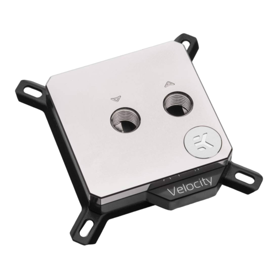
- Page 1 Velocity – Intel CPU WATER BLOCK Velocity CPU WATER BLOCK USER MANUAL - 3rd Revision, July 27th 2021...
- Page 2 The following instructions are subject to change without notice. Please visit our website at www.ekwb.com for updates. Before installation of this product, please read important notice, disclosure, and warranty conditions that are printed on the back of the box.
-
Page 3: Table Of Contents
TABLE OF CONTENT GENERAL INFORMATION ON WATER BLOCK COMPATIBILITY SUPPORT AND SERVICE BOX CONTENTS SOCIAL MEDIA WATER BLOCK DIMENSIONS TECHNICAL SPECIFICATIONS AND WATER BLOCK PARTS QUICK INSTALLATION GUIDE REPLACING THE JET PLATE PROCEDURE INSTALLING THE WATER BLOCK LGA-2011(-3) / 2066 SOCKET MOTHERBOARDS LGA-115X SOCKET MOTHERBOARDS CONNECTING THE RGB LED STRIP (Optional) CONNECTING THE RGB LED STRIP... -
Page 4: General Information On Water Block Compatibility
GENERAL INFORMATION ON WATER BLOCK COMPATIBILITY This CPU liquid cooling unit is pre-assembled for use with modern Intel desktop socket type motherboards. By default (out of the box) this water block supports the following CPU sockets: - Intel LGA-1150/1151/1155/1156 - Intel LGA-1200 - Intel LGA-2011(-3) - Intel LGA-2066 - 4 -... - Page 5 BOX CONTENTS Universal Mounting Mechanism – You may not need every screw from this package. EAN: 3831109813065 Spring (4 pcs) Standoff - LGA 115x / AMD (4 pcs) EK-Velocity universal CPU water block with the Intel bracket (1 pc) Standoff - 20xx (4 pcs) Washer (5 pcs) Backplate Rubber Gasket (1 pc) Metal Backplate LGA-115x / LGA-1200 (1 pc)
-
Page 6: Water Block Dimensions
WATER BLOCK DIMENSIONS 90.7 mm 22 mm 68.3 mm - 6 -... -
Page 7: Technical Specifications And Water Block Parts
TECHNICAL SPECIFICATIONS AND WATER BLOCK PARTS Technical Specification: - Dimensions (L x H x W): 91 x 91 x 22 mm - D-RGB cable length: 500 mm - D-RGB LED count: 20 - D-RGB connector standard 3-pin (+5V, Data, Blocked, Ground) Position EAN Description Quantity... - Page 8 Technical Specification: - Dimensions (L x H x W): 91 x 91 x 22 mm - D-RGB cable length: 500 mm - D-RGB LED count: 1 - D-RGB connector standard 3-pin (+5V, Data, Blocked, Ground) Position EAN Description Quantity 100668 COLDPLATE - Copper 100669 COLDPLATE - Nickel...
- Page 9 Technical Specification: - Dimensions (L x H x W): 91 x 91 x 22 mm - D-RGB cable length: 500 mm - D-RGB LED count: 1 - D-RGB connector standard 3-pin (+5V, Data, Blocked, Ground) Position EAN Description Quantity 100668 COLDPLATE - Copper 100669 COLDPLATE - Nickel...
- Page 10 REPLACING THE JET PLATE PROCEDURE STEP 1 Please reference the table below to determine the optimal insert and jet plate needed for your type of socket. Socket Optimal Jet LGA-115x / LGA-1200 LGA-2011(-3) LGA-2066 d= 1 mm d= 0.8 mm STEP 2 Unscrew the four M4 screws in counter-clock-wise direction from the bottom of the water block using the enclosed 2.5 mm Allen key to release...
- Page 11 INSTALLING THE WATER BLOCK LGA-2011(-3) / 2066 SOCKET MOTHERBOARDS LGA-2011 M3 LGA-2011 M3 THUMB SCREW THUMB SCREW STEP 1 Prepare the foil bag with mounting mechanism, which is enclosed with the CPU water block delivery. Install four (4) specific LGA-2011 M3 thumb screws into four M3 threaded stubs on the LGA-2011 socket integrated latch mecha- nism (ILM).
- Page 12 STEP 3 THUMB NUT Align the water block over the mounting screws on the LGA-2011(-3) motherboard with pre-installed CPU. COILED SPRING Before proceeding with the installation, it is mandatory to remove the protective foil from the backside of the water block. Place an enclosed compression spring and thumb nut over each M3 thumb screw.
- Page 13 LGA-115x SOCKET MOTHERBOARDS STEP 1 If already installed, please remove the motherboard from your computer and place it on an even surface with front facing down. OUTER PART STEP 2 Preparing backplate rubber gasket The enclosed rubber gasket is an essential part of the backplate and mounting system and must be used every time you install this water block on your motherboards.
- Page 14 STEP 4 Install four (4) M3 thumb screws onto your motherboard. It is M3 THUMB mandatory to put 0.7mm plastic washer underneath each of the SCREW M3 thumb screws. Tighten the screws to the metal backplate until you reach the end of the thread. Using tools (such as pliers) is not recommended.
- Page 15 CONNECTING THE RGB LED STRIP STEP 1 Plug the 4-pin connector from the water block and fan’s RGB LED light to the RGB HEADER on the motherboard. The LED will work if the pin layout on the header is as follows: +12V G R B. D-RGB HEADER Please ensure that the arrow indicated on the connector is plugged into the +12V line as indicated on your...
- Page 16 Connector is the same on D-RGB and RGB versions, but D-RGB version has 3 cables from connector to PCB; RGB version has 4 cables. If you connect D-RGB LED to ordinary RGB header you can damage your motherboard D-RGB LED Connector or LED strip.
-
Page 17: Support And Service
SUPPORT AND SERVICE In case you need assistance or wish to order spare parts or a new mounting mechanism, please contact: https://www.ekwb.com/customer-support/ For spare parts orders, refer to the page with “TECHNICAL SPECIFICATIONS AND WATER BLOCK PARTS” where you can find the EAN number of each part you might need.
Need help?
Do you have a question about the Velocity – Intel and is the answer not in the manual?
Questions and answers