Siemens SIMATIC S7-1500 Manual
Hide thumbs
Also See for SIMATIC S7-1500:
- System manual (523 pages) ,
- Function manual (402 pages) ,
- Manual (188 pages)
Table of Contents
Advertisement
Advertisement
Table of Contents

Related Manuals for Siemens SIMATIC S7-1500


Summary of Contents for Siemens SIMATIC S7-1500
- Page 2 ___________________ CPU 1515-2 PN Preface (6ES7515-2AM00-0AB0) ___________________ Documentation guide ___________________ SIMATIC Product overview ___________________ Connecting up S7-1500 CPU 1515-2 PN Interrupts, error messages, ___________ diagnostics and system (6ES7515-2AM00-0AB0) alarms ___________________ Manual Technical specifications ___________________ Dimensional drawing 12/2014 A5E32332431-AB...
- Page 3 Note the following: WARNING Siemens products may only be used for the applications described in the catalog and in the relevant technical documentation. If products and components from other manufacturers are used, these must be recommended or approved by Siemens. Proper transport, storage, installation, assembly, commissioning, operation and maintenance are required to ensure that the products operate safely and without any problems.
-
Page 4: Preface
Siemens recommends strongly that you regularly check for product updates. For the secure operation of Siemens products and solutions, it is necessary to take suitable preventive action (e.g. cell protection concept) and integrate each component into a holistic, state-of-the-art industrial security concept. -
Page 5: Table Of Contents
Table of contents Preface ..............................4 Documentation guide ..........................6 Product overview ............................ 8 Application ..........................8 How it works ..........................10 Properties ..........................11 Operating and display elements ..................... 14 2.4.1 Front view of the module with closed front panel ..............14 2.4.2 Front view of the module without front panel ................ -
Page 6: Documentation Guide
This arrangement enables you to access the specific content you require. Basic information System Manual and Getting Started describe in detail the configuration, installation, wiring and commissioning of the SIMATIC S7-1500 and ET 200MP systems. The STEP 7 online help supports you in the configuration and programming. Device information Product manuals contain a compact description of the module-specific information, such as properties, terminal diagrams, characteristics and technical specifications. - Page 7 Documentation guide Manual Collection S7-1500/ET 200MP The Manual Collection contains the complete documentation on the SIMATIC S7-1500 automation system and the ET 200MP distributed I/O system gathered together in one file. You can find the Manual Collection on the Internet (http://support.automation.siemens.com/WW/view/en/86140384).
-
Page 8: Product Overview
Product overview Application The CPUs of the SIMATIC S7-1500 controller family offer best possible performance combined with excellent usability. With their integrated PROFINET/PROFIBUS interfaces, the Web server and integrated functionalities, such as Motion Control, PID controller and temperature controller, trace support, the CPUs are predestined for numerous applications in automation engineering. - Page 9 2.1 Application Integrated technology functions The CPUs of the SIMATIC S7-1500 family support Motion Control functions. STEP 7 offers PLCopen standardized blocks for configuring and connecting a drive to the CPU. Motion Control supports speed, positioning and synchronous axes, as well as external encoders.
-
Page 10: How It Works
Product overview 2.2 How it works Design and handling The design and handling of the CPUs is very straightforward and offers the greatest possible user friendliness. All CPUs have a display. The display provides information on order numbers, firmware version and serial numbers of all connected modules. The IP address of the CPU and other network settings can be set directly on site, without a programming device. -
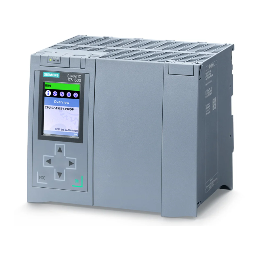
Page 11: Properties
Product overview 2.3 Properties Properties Article number 6ES7515-2AM00-0AB0 View of the module The following figure shows the CPU 1515-2 PN. Figure 2-1 CPU 1515-2 PN Note Protective film Note that a protective film is attached to the display of the CPU when shipped from the factory. - Page 12 Product overview 2.3 Properties Properties The CPU 1515-2 PN has the following technical properties: ● Communication: – Interfaces CPU 1515-2 PN has two PROFINET interfaces. The 1st PROFINET interface (X1) has two ports (P1R and P2R). In addition to PROFINET basic functionality, it also supports PROFINET IO RT (Realtime) and IRT (Isochronous Realtime).
- Page 13 Product overview 2.3 Properties ● Integrated technology: – Motion Control PLC-Open blocks for programming motion functionality using PROFINET IO IRT with the PROFIdrive interface. The functionality supports speed-controlled axes, positioning axes, synchronous axes and external encoders. – Integrated closed-loop control functionality - Universal PID controller and 3-point controller with integrated tuning - Integrated temperature controller ●...
-
Page 14: Operating And Display Elements
2.4 Operating and display elements Reference You will find additional information on the topic of "Integrated security/Access protection" in the S7-1500/ET 200MP system manual (http://support.automation.siemens.com/WW/view/en/59191792). Operating and display elements 2.4.1 Front view of the module with closed front panel The following figure shows the front view of the CPU 1515-2 PN. - Page 15 S7-1500/ET 200MP (http://support.automation.siemens.com/WW/view/en/59191792) system manual. Reference You will find detailed information on the individual display options, a training course and a simulation of the available menu commands in the SIMATIC S7-1500 Display Simulator (http://www.automation.siemens.com/salesmaterial-as/interactive-manuals/getting- started_simatic-s7-1500/disp_tool/start_en.html). CPU 1515-2 PN (6ES7515-2AM00-0AB0)
-
Page 16: Front View Of The Module Without Front Panel
Product overview 2.4 Operating and display elements 2.4.2 Front view of the module without front panel The following figure shows the operator controls and connection elements of the CPU 1515-2 PN. ① LEDs for the current operating mode and diagnostic status of the CPU ②... -
Page 17: Rear View Of The Module
Product overview 2.5 Mode selector switch 2.4.3 Rear view of the module The following figure shows the connection elements on the rear of the CPU 1515-2 PN. ① Shield contact surfaces ② Backplane bus connector ③ Fixing screws Figure 2-5 View of the CPU 1515-2 PN - rear Mode selector switch Use the mode switch to set the CPU operating mode. -
Page 18: Functions
● IO controller ● Shared device ● Isochronous mode Reference You can find additional information on the "PROFINET IO" topic in the STEP 7 online help and in the PROFINET System Description (http://support.automation.siemens.com/WW/view/en/19292127) manual. CPU 1515-2 PN (6ES7515-2AM00-0AB0) Manual, 12/2014, A5E32332431-AB... -
Page 19: Profienergy
The majority of the energy is saved by the process; the PROFINET device itself only contributes a few watts of savings potential. Additional information ● PROFINET (http://support.automation.siemens.com/WW/view/en/68039307) function manual ● You will find more information on PROFIenergy in the PROFINET specification on the Internet (http://www.profibus.com). - Page 20 * The retentive tags of technology objects are retained, but the contents of certain tags are partially re-initialized. Reference You will find more information about "Memory reset" in the Memory reset section in the S7-1500, ET 200MP (http://support.automation.siemens.com/WW/view/en/59191792) system manual. CPU 1515-2 PN (6ES7515-2AM00-0AB0)
-
Page 21: Restoring The Factory Settings Of The Cpu
Product overview 2.6 Functions 2.6.4 Restoring the factory settings of the CPU The reset to factory settings function restores the CPU to the factory settings. The function deletes all information that was stored internally on the CPU. Note If you want to remove a PROFINET CPU and use it elsewhere with a different program or put it into storage, we recommend that you reset the CPU to its factory settings. - Page 22 Product overview 2.6 Functions Procedure using the display Make sure that the CPU is in STOP mode (RUN/STOP LED lit yellow). You can reach the "Factory settings" menu command by selecting the following menu commands one after the other and confirming each selection with "OK". ●...
- Page 23 Reference You can find more information about the topic of "Reset to factory settings" in the function manual Structure and Use of the CPU Memory (http://support.automation.siemens.com/WW/view/en/59193101) as well as in the STEP 7 online help. CPU 1515-2 PN (6ES7515-2AM00-0AB0) Manual, 12/2014, A5E32332431-AB...
-
Page 24: Connecting Up
Connecting up This section provides information on the terminal assignment of the individual interfaces and the block diagram of the CPU 1515-2 PN. 24 V DC supply voltage (X80) The connector for the power supply is plugged in when the CPU ships from the factory. The following table shows the terminal assignment for a 24 V DC power supply. - Page 25 The pin assignments of the PROFINET interfaces X1 and X2 are identical. Reference You can find additional information on the topics of "Connecting the CPU" and "Accessories/spare parts" in the S7-1500, ET 200MP (http://support.automation.siemens.com/WW/view/en/59191792) system manual. CPU 1515-2 PN (6ES7515-2AM00-0AB0) Manual, 12/2014, A5E32332431-AB...
- Page 26 Connecting up Assignment of the MAC addresses The CPU 1515-2 PN has two PROFINET interfaces, with the first interface having two ports. The PROFINET interfaces each have a MAC address, and each of the PROFINET ports has its own MAC address. The CPU 1515-2 PN therefore has five MAC addresses in total. The MAC addresses of the PROFINET ports are needed for the LLDP protocol, for example for the neighborhood discovery function.
- Page 27 Connecting up Block diagram The following figure shows the block diagram of the CPU 1515-2 PN. ① Display PN X1 P1 R PROFINET interface X1 Port 1 ② RUN/STOP/MRES mode selector PN X1 P2 R PROFINET interface X1 Port 2 ③...
-
Page 28: Interrupts, Error Messages, Diagnostics And System Alarms
The status and error displays of the CPU 1515-2 PN are described below. You will find additional information on "Interrupts" in the STEP 7 online help. You can find additional information on the topics of "Diagnostics" and "System alarms" in the Diagnostics (http://support.automation.siemens.com/WW/view/en/59192926) function manual. Status and error display of the CPU LED display The figure below shows the CPU 1515-2 PN LEDs. - Page 29 Interrupts, error messages, diagnostics and system alarms 4.1 Status and error display of the CPU Meaning of the LED displays The CPU 1515-2 PN has three LEDs to signal the current operating status and diagnostics status. The following table shows the meaning of the various combinations of colors for the RUN/STOP, ERROR and MAINT LEDs.
- Page 30 Interrupts, error messages, diagnostics and system alarms 4.1 Status and error display of the CPU Meaning of the LEDs of the interfaces: X1 P1 R, X1 P2 R and X2 P1 Each port has a LINK RX/TX LED. The table below shows the various "LED scenarios" of ports for the CPU 1515-2 PN.
-
Page 31: Technical Specifications
Technical specifications 6ES7515-2AM00-0AB0 Product type designation CPU 1515-2 PN General information Hardware product version FS02 Firmware version V1.7 Engineering with STEP 7 TIA Portal can be configured/integrated V13 SP1 as of version Display Screen diagonal (cm) 6.1 cm Operator controls Number of buttons Mode selector Supply voltage... - Page 32 Technical specifications 6ES7515-2AM00-0AB0 CPU processing time For bit operations, typ. 30 ns For word operations, typ. 36 ns For fixed-point arithmetic, typ. 48 ns For floating-point arithmetic, typ. 192 ns CPU blocks Number of elements (total) 6000; elements can be taken to mean blocks such as DBs, FBs and FCs, as well as UDTs, global constants etc.
- Page 33 Technical specifications 6ES7515-2AM00-0AB0 IEC counters Quantity Unlimited (limited only by work memory) Retentivity Adjustable • S7 timers Quantity 2048 Retentivity Adjustable • IEC timers Quantity Unlimited (limited only by work memory) Retentivity Adjustable • Data areas and their retentivity Total retentive data area (including timers, 512 KB;...
- Page 34 Technical specifications 6ES7515-2AM00-0AB0 Hardware configuration Number of hierarchical IO systems Number of DP masters Via CM 8; a maximum of 8 CMs/CPs (PROFIBUS, PROFINET, Ethernet) can be inserted in total Number of IO controllers Integrated Via CM 8; a maximum of 8 CMs/CPs (PROFIBUS, PROFINET, Ethernet) can be inserted in total Rack Modules per rack, max.
- Page 35 Technical specifications 6ES7515-2AM00-0AB0 2. Interface Interface hardware Number of ports • Integrated switch • Yes; X2 RJ-45 (Ethernet) • Protocols PROFINET IO controller • PROFINET IO device • SIMATIC communication • Open IE communication • Web server • Interface hardware RJ-45 (Ethernet) 100 Mbps Autonegotiation...
- Page 36 Technical specifications 6ES7515-2AM00-0AB0 Number of IO devices that you can connect for • RT, max. Of which are in line, max. • Number of IO devices that can be activated/ • deactivated simultaneously, max. Number of IO devices per tool changer, max. •...
- Page 37 Technical specifications 6ES7515-2AM00-0AB0 SIMATIC communication S7 communication, as server S7 communication, as client User data per job, max. See online help (S7 communication, user data size) Open IE communication TCP/IP 64 KB Data length, max. • Several passive connections per port, •...
- Page 38 Technical specifications 6ES7515-2AM00-0AB0 Test/commissioning functions Joint commissioning (Team Engineering) Yes; parallel online access possible for up to 8 engineering systems Status block Yes; up to 8 simultaneously (in total from all ES clients) Single-step Status/modify Status/modify tag Tags Inputs, outputs, bit memories, DBs, timers, counters Of which are status tags, max.
- Page 39 Technical specifications 6ES7515-2AM00-0AB0 Controller Yes; universal PID controller with integrated PID_Compact • optimization Yes; PID controller with integrated optimization PID_3Step • for valves Yes; PID controller with integrated optimization PID temp • for temperature Counting and measuring High-speed counter • Ambient conditions Ambient temperature in operation Horizontal installation, min.
- Page 40 Technical specifications General technical specifications You can find information on the general technical specifications, such as standards and approvals, electromagnetic compatibility, protection class, etc., in the S7-1500, ET 200MP (http://support.automation.siemens.com/WW/view/en/59191792) system manual. CPU 1515-2 PN (6ES7515-2AM00-0AB0) Manual, 12/2014, A5E32332431-AB...
-
Page 41: Dimensional Drawing
Dimensional drawing This section contains the dimensional drawing of the module on the mounting rail, as well as a dimensional drawing with the front panel open. Keep to the dimensions when installing in cabinets, control rooms, etc. Dimensional drawings for CPU 1515-2 PN Figure A-1 Dimensional drawing of CPU 1515-2 PN, front and side views Figure A-2...