Planmeca ProOne Manual
Hide thumbs
Also See for ProOne:
- Technical manual (195 pages) ,
- User manual (116 pages) ,
- Installation manual (48 pages)
Table of Contents
Advertisement
Quick Links
Advertisement
Table of Contents

Related Manuals for Planmeca ProOne


Summary of Contents for Planmeca ProOne
- Page 1 Planmeca ProOne ® installation manual...
-
Page 3: Table Of Contents
Connecting the Ethernet cable ....................32 Configuring the Ethernet link ..................... 33 Checking the Ethernet link communication ................34 Installing the Romexis imaging software ................... 34 Sensor calibration files ......................34 POST-INSTALLATION CHECK LIST ................. 35 DIAGRAMS ........................37 Installation Manual Planmeca ProOne... - Page 4 - equipment is used according to the operating instructions. - equipment is used according to the operating instructions. Planmeca pursues a policy of continual product development. Although every effort is Planmeca pursues a policy of continual product development. Although every effort is...
-
Page 5: Introduction
1 INTRODUCTION 1 INTRODUCTION This manual contains the information required to install the Planmeca ProOne X-ray unit. Please read this manual carefully before installing the X-ray unit. NOTE Required software versions: • Planmeca ProOne software version 1.9.0.0.r or later •... -
Page 6: Pre-Installation Requirements
RF communications equipment and the X-ray unit, see Technical manual, section “EMC INFORMATION”. NOTE FOR PERMANENTLY INSTALLED X-RAY UNITS The X-ray unit can be disconnected from the mains power supply by turning the external mains switch to the off position. Planmeca ProOne Installation Manual... -
Page 7: Environmental Requirements
WARNING FAILURE TO INSTALL THE X-RAY UNIT IN AN APPROVED LOCATION MAY BE DANGEROUS TO BOTH PATIENT AND OPERATOR. Protect yourself from radiation when you check the radiation beam alignment. Installation Manual Planmeca ProOne... -
Page 8: Wall Strength
In order to fulfill the safety directives, the X-ray unit must be connected to ground in the junction box. 3.6 Digital system requirements The digital system consists of a Planmeca ProOne X-ray unit, Ethernet card, one or more PCs and an imaging software (Romexis) package. The PC(s) connected to the system must be: •... -
Page 9: Network Architecture Requirements
Connecting the X-ray system to a network that contains other devices, or making any changes to this network, could result in previously unidentified risks to patients, operators or third parties. These risks must be identified, analysed, evaluated and controlled by the responsible organisation. Installation Manual Planmeca ProOne... -
Page 10: Space Requirements
3 PRE-INSTALLATION REQUIREMENTS 3.8 Space requirements The following table lists the space requirements for the Planmeca ProOne X-ray unit. Unit dimensions • 969 (W) x 1030* (D) x 2224 (H) mm • 38.1 (W) x 40.6 * (D) x 87.6 (H) in. - Page 11 3 PRE-INSTALLATION REQUIREMENTS 969 mm 38.1 in. 491mm 478 mm 19.3 in. 18.8 in. = + 10 mm (0.4 in.) with optional extension plate Installation Manual Planmeca ProOne...
- Page 12 3 PRE-INSTALLATION REQUIREMENTS 3.8.2 Minimum required space The following figure shows the recommended practical operational space requirements for the Planmeca ProOne X-ray unit. +400 mm +100 mm +15.7” +3.9” +300 mm +11.8” Distance from wall (depth) includes additional + 10 mm (0.4 in.) extension plate measured...
-
Page 13: Dimensions For Wall Bracket And Optional Extension Plate
3.9 Dimensions for wall bracket and optional extension plate Figure 1: Wall bracket 180 mm (7.1 in.) 150 mm (5.9 in.) Extension plate for wall bracket (optional Figure 2: 10 mm (0.4 in.) 240 mm (9.45 in.) 406.4 mm (16 in.) Installation Manual Planmeca ProOne... -
Page 14: Main Parts
4 MAIN PARTS 4 MAIN PARTS 4.1 General view of the system X-ray unit Exposure switch NOTE: PC MUST BE PLACED OUTSIDE PATIENT AREA Patient area Romexis imaging software Ethernet Planmeca ProOne Installation Manual... -
Page 15: General View Of The X-Ray Unit
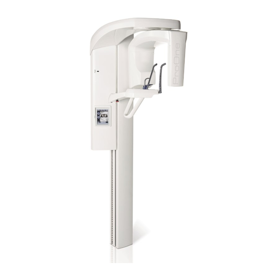
4 MAIN PARTS 4.2 General view of the X-ray unit C-arm Patient supports Patient support table Patient handles Emergency stop button Control panel Moving column Stationary column Safety plate Installation Manual Planmeca ProOne... -
Page 16: Contents Of The Packing
5 CONTENTS OF THE PACKING 5 CONTENTS OF THE PACKING Planmeca ProOne X-ray unit Package protective parts Upper arm cover Accessories carton Planmeca ProOne Installation Manual... -
Page 17: Unpacking The X-Ray Unit
Fold down the side flaps (2) and remove the protective parts (3), upper arm cover (4) and accessories carton (5). Attach felt pads here! NOTE Do not remove the support frame until the X-ray unit has been attached to the wall. Installation Manual Planmeca ProOne... - Page 18 X-ray unit. Lift up the X-ray unit and the support frame (6). NOTE Never lift the X-ray unit from the patient handles. Remove the two transport locking pins from the back of the X-ray unit. Planmeca ProOne Installation Manual...
-
Page 19: Installing The X-Ray Unit
NOTE For dimensions of the wall bracket and the optional extension plate, see section 3.9 "Dimensions for wall bracket and optional extension plate" on page 11. For installation drawing, see section 11 "DIAGRAMS" on page 37. Installation Manual Planmeca ProOne... - Page 20 Drill two securing holes (ø7 mm (0.3 in.), 70…75 mm (2.75...3 in.) in depth) for the mounting screws. If needed, place protective caps (included in the delivery) on the lag screws. Wall made of concrete or stone Wooden wall ~1700mm (66.9 in.) Planmeca ProOne Installation Manual...
- Page 21 If needed, use cover plugs (included in the delivery) to close unneeded holes in the extension plate. Wall made of concrete or stone Extension plate (optional) Wooden wall ~1700mm (66.9 in.) Installation Manual Planmeca ProOne...
- Page 22 NOTE Use a spirit level to ensure that the column is vertical. Attachment screws Clamp (two on each side) Guide rail (view as seen from the side of the wall) Planmeca ProOne Installation Manual...
-
Page 23: Attaching The X-Ray Unit To The Floor
Loosen the four wall bracket attachment screws and carefully pull the X-ray unit away from the wall so that you can drill the floor holes. Loosen the screws (two on each side) (view as seen from the side of the wall) Installation Manual Planmeca ProOne... - Page 24 Drill two securing holes (ø5 mm (0.2 in.), 45…50 mm (1.9 in.) in depth) for the mounting screws. Floor made of concrete or stone Tighten the screws a couple of turns. Planmeca ProOne Installation Manual...
- Page 25 Secure the X-ray unit in position by tightening the four wall bracket attachment screws and the two floor mounting screws to full tightness. NOTE Use a spirit level to ensure that the column is vertical. Remove the wooden support frame and the styrofoam packaging. Installation Manual Planmeca ProOne...
-
Page 26: Attaching The Upper Arm Cover
Fasten one screw, then manually slide the C-arm to the other side so that you can fasten the other screw. Upper arm cover Upper arm frame 7.4 Attaching the safety plate Place the safety plate in position. Planmeca ProOne Installation Manual... -
Page 27: Connecting The Power Cable
Attach the strain relief to the power cable. If needed, shorten the length of the power cable. Route the wires of the power cable into the junction box. Attach the junction box to the wall according to the local regulations. Installation Manual Planmeca ProOne... - Page 28 Attach the cover plate to the junction box. NOTE If you need to connect an existing power cable directly to the X-ray unit, refer to the wiring diagram for an existing permanently installed power cable in section 11 "DIAGRAMS" on page 37. Planmeca ProOne Installation Manual...
- Page 29 7 INSTALLING THE X-RAY UNIT 7.5.2 X-ray units with detachable power supply cord (power cable with plug) Connect the plug to a wall socket with a suitable voltage rating. Installation Manual Planmeca ProOne...
-
Page 30: Installing The Exposure Switch
CAUTION Only the Planmeca cross connection spiral cable (Planmeca part no. 10001193) can be used between the ProOne X-ray unit and the exposure switch. This cable can be lengthened with an RJ12 Coupler and a Modular extension cable (6wire with 2xRJ12). - Page 31 The left hand side terminal is a USB port and it is reserved for a USB memory stick. Do not plug any other USB devices into the USB port. Ferrite bead Back of moving column Exposure switch cable Screws that hold the protective cover in position Connect the other cable end to the exposure switch. Installation Manual Planmeca ProOne...
-
Page 32: Stationary Exposure Switch
Connect the exposure switch cable to the terminal on the back of the moving column. To do this, you will first have to remove the cover that protects the terminals. Remove the protective cover by unscrewing the two screws at the bottom and then unlatching the cover at the top. Planmeca ProOne Installation Manual... - Page 33 The left hand side terminal is a USB port and it is reserved for a USB memory stick. Do not plug any other USB devices into the USB port. Ferrite bead Back of moving column Exposure switch cable Screws that hold the protective cover in position Connect the other cable end to the exposure switch. Installation Manual Planmeca ProOne...
-
Page 34: Installing The Digital System
9 INSTALLING THE DIGITAL SYSTEM 9.1 Connecting the Ethernet cable The ProOne X-ray unit is connected to the local (10/100 Base) network and used from a PC with the Romexis imaging software. Use an Ethernet cable to connect the X-ray unit to the network. -
Page 35: Configuring The Ethernet Link
The correct Ethernet link cable needs to be connected to the X-ray unit (see section 9.1 “Connecting the Ethernet cable” on page 32). The Ethernet settings of the ProOne X-ray unit must be configured (see below). The IP Address and IP Port (5005) must then be entered in the DIDAPI configuration program (Ethernet Interface settings). -
Page 36: Checking The Ethernet Link Communication
The Ethernet link communication from the PC to the ProOne X-ray unit can be checked by opening the Command Prompt and executing the command “ping <ProOne IP address>”, e.g. ping 192.168.3.220. The ProOne X-ray unit will send a reply message (4 packets) if the Ethernet link is up and running. NOTE If you do not receive a reply message (e.g. -
Page 37: Post-Installation Check List
Technical Manual, section “Taking a ball phantom exposure”. If necessary, adjust the position of the patient support table and C-arm according to the instructions given in the Technical Manual. Emergency stop button Check the emergency stop button functionality. Installation Manual Planmeca ProOne... - Page 38 10 POST-INSTALLATION CHECK LIST Planmeca ProOne Installation Manual...
-
Page 39: Diagrams
11 DIAGRAMS 11 DIAGRAMS Installation Manual Planmeca ProOne... - Page 42 Planmeca ProOne Remote Button EU 06.03.2017 LY Data wall socket connection Modular Jack Exposure switch RJ-12 Exposure Spiral Cable +26V EXP Lamp Ready Lamp PC with grabber card Data wall socket assemble 06001019 Exposure switch NOTE 10029350 Cross connected Cable...
- Page 44 Planmeca ProOne Remote Button US 06.03.2017 LY Modular Jack Exposure switch RJ-12 Exposure Spiral Cable +26V EXP Lamp Ready Lamp PC with grabber card Data wall socket assembly 06001019 NOTE Exposure switch Cross connected Cable 10029350 Ethernet cable UTP cat5e...
- Page 46 Planmeca ProOne Double Exposure Switch / Lamp Remote connection EU 27.02.2017 LY Optional Exposure Lamp PC Image Capture USB Memory Ethernet Ethernet cable CAT6 UTP Exposure Cable 10027515 Exposure Switch 10001193 Remote Exposure Option NOTE! ELECTRICALLY CROSS-CONNECTED NOTE! The last...
- Page 48 Planmeca ProOne Double Exposure Switch / Lamp Remote connection US 13.03.2014 LY Optional Exposure Lamp PC Image Capture Ethernet cable CAT6 UTP Exposure Cable 10027515 10001193 USB Memory Ethernet Exposure Switch Remote Exposure Option NOTE! ELECTRICALLY CROSS-CONNECTED NOTE! The last...
- Page 50 Planmeca ProOne Exposure Lamp Remote connection EU 27.02.2017 LY Optional Exposure Lamp PC Image Capture Ethernet cable CAT6 UTP USB Memory Ethernet 10027515 Exposure Switch Exposure Cable Remote Exposure Option 10001193 (electrically cross-connected) RDYIND <--> 1 EXPIND <--> 2 <--> 5 EXPIN <-->...
- Page 52 Planmeca ProOne Exposure Lamp Remote connection US 12.06.2014 LY Optional Exposure Lamp PC Image Capture USB Memory Ethernet Exposure Switch Ethernet cable CAT6 UTP 10027515 Remote Exposure Option Exposure Cable 10001193 (electrically cross-connected) RDYIND <--> 1 EXPIND <--> 2 <--> 5 EXPIN <-->...
- Page 54 NOTE • The quality and cross-sectional area of the existing power cable must fulfill the requirements of the local standards (must be e.g. IEC approved (CE marked), UL / CSA approved). ProOne Permanent Installation 06.06.2016 LY ProOne Input Module Existing power cable...
- Page 57 Planmeca Oy | Asentajankatu 6 | 00880 Helsinki | Finland tel. +358 20 7795 500 | fax +358 20 7795 555 | sales@planmeca.com | www.planmeca.com...
Need help?
Do you have a question about the ProOne and is the answer not in the manual?
Questions and answers