Table of Contents
Advertisement
Quick Links
STIHL 064, 066
SERVICE MANUAL
064 and 066
Chain Saws
As the design concept of these two models is
almost identical, the descriptions and
servicing procedures generally apply to both.
Differences are described in detail.
You should make use of the illustrated parts
lists while carrying out repair work. They
show the installed positions of the individual
components and assemblies. Microfilmed
parts list are always more up to date than
printed lists.
A fault on the machine may have several
causes. Consult the "troubleshooting charts"
when tracing faults.
Refer to the "Technical Information Bulletins"
for engineering changes which have been
introduced since publication of this service
manual.
Service manuals and technical information
bulletins describing engineering changes are
intended exclusively for the use of STIHL
servicing dealers and staff and must not be
passed on to third parties.
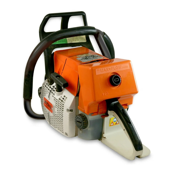
Chain saw on assembly stand
Servicing and repairs are made
considerably easier if the saw is mounted
on assembly stand 5910 850 3100 or 5910
890 3100. This enables the saw to be
swivelled to the best position for the
ongoing repair and thus leaves both hands
free.
The saw is can be quickly secured to the
stand by means of the two bar mounting
studs and nuts.
The STIHL Special Tools manual lists all
special servicing tools currently available
from STIHL.
Always use original STIHL replacement
parts.
Original STIHL parts can be identified by
the STIHl part number, the
and the STIHL parts symbol. (
The symbol may appear alone on small
parts.
© 1992 Andreas Stihl. Waiblingen
1
logo
Advertisement
Table of Contents

Related Manuals for Stihl 064


Summary of Contents for Stihl 064
- Page 1 064 and 066 Chain Saws Chain saw on assembly stand As the design concept of these two models is The STIHL Special Tools manual lists all almost identical, the descriptions and special servicing tools currently available servicing procedures generally apply to both.
-
Page 2: Table Of Contents
STIHL 064, 066 CONTENTS Specifications Leakage Testing the Electric Handle Heating System Crankcase Engine 4.6.1 Preparations Fuel System 4.6.2 Pressure Test Troubleshooting Ignition System 4.6.3 Vacuum Test 9.1.1 Troubleshooting Chart Cutting Attachment Replacing the Oil Seals 9.1.2 Test Connections and... -
Page 3: Specifications
STIHL 064, 066 SPECIFICATIONS Engine STIHL single-cylinder two-stroke engine Displacement: 85 cm³ (5.2 cu.in) 91.6 cm³ (5.6 cu.in) Bore: 52 mm (2.05 in) 54 mm (2.12 in) Stroke: 40 mm (1.6 in) 40 mm (1.6 in) Compression ratio: 10.0 10.0 Power output: 4.8 kW (6.5 bhp) -
Page 4: Fuel System
0.84 I (1.77 US pt) Fuel mixture: Regular brand-name gasoline and brand-name two-stroke engine oil Mix ratio: 50:1 50:1 with STIHL two-stroke engine oil with STIHL two-stroke engine oil 25:1 25:1 with other brand-name two-stroke, with other brand-name two-stroke, air-cooled engine oils... -
Page 5: Ignition System
STIHL 064, 066 Ignition System Type: Electronic magneto Digital magneto ignition (breakerless) ignition (breakerless) with integral trigger with maximum speed unit governor Air gap: 0.2-0.3 mm (0.008-0.012 in) 0.2-0.3 mm (0.008-0.012 in) Ignition timing: 2.6-3.4 mm 2.9-3.9 mm (0.10-0.13 in) B.T.D.C. - Page 6 STIHL 064, 066 Oilomatic chain: 3/8" (9.32 mm) 3/8" (9.32 mm) Rapid Micro and Super Rapid Micro and Super (standard) (standard) 0.404" (10.26 mm) 0.404" (10.26 mm) Rapid Micro and Rapid Super Rapid Micro and Rapid Super (optional) (optional) Chain sprocket: 8-tooth 3/8"...
-
Page 7: Tightening Torques
STIHL 064, 066 Tightening Torques Fastener Thread size For component Torque Remarks (Ibf.ft) Spline screw IS-M5x20 Crankcase (6.6) Spline screw IS-M5x20 Cylinder 12.0 (8.8) Spline screw IS-M6x20 Cylinder 15.0 (11.8) Spline screw IS-M5x12 Muffler to cylinder 10.0 (7.5) 1)2) Spline screw... -
Page 8: Special Accessories
STIHL 064, 066 Special Accessories 064 / 066 1.6.1 For User STIHL repair kit 064 1122 900 5000 Intake air preheating kit 1122 007 1027 7-tooth 0.404" rim sprocket kit 1122 007 1002 8-tooth 3/8" spur sprocket 1122 640 2000 7-tooth 0.404"... -
Page 9: Troubleshooting Charts
STIHL 064, 066 TROUBLESHOOTING CHARTS Clutch, Chain Drive, Chain Brake and Chain Tensioner Condition Cause Remedy Saw chain turns at Engine idle speed too high Readjust at idle speed idle speed adjustment screw (counterclockwise) Fit new spring(s) Spring hook(s) broken... -
Page 10: Engine
STIHL 064, 066 Engine Always check and, if necessary, repair the following parts before looking for faults on the engine: - Air filter - Fuel system - Carburetor - Ignition system Condition Cause Remedy Engine does not start Oil seals in crankcase... -
Page 11: 2.3 Ignition System
STIHL 064, 066 2.3 Ignition System Warning: Exercise extreme caution while carrying out maintenance and repair work on the ignition system. The high voltages which occur can cause serious or fatal accidents! Spark plug terminal firmly seated on spark plug? Remove spark plug. -
Page 12: Rewind Starter
STIHL 064, 066 Rewind Starter Condition Cause Remedy Starter rope broken Rope pulled out too Fit new starter rope vigorously as far as stop or over edge - i.e. not vertically Normal wear Fit new starter rope Rewind spring broken... -
Page 13: Chain Lubrication
STIHL 064, 066 Chain Lubrication Important: In the event of trouble with the chain lubrication system, always investigate the other possible sources of faults before disassembling the oil pump. Condition Cause Remedy Chain receives Oil tank empty Fill up with oil... -
Page 14: Fuel System
STIHL 064, 066 Fuel System Condition Cause Remedy Carburetor floods; Inlet needle not sealing. Foreign Remove and clean or replace engine stalls matter in valve seat or cone inlet needle, clean fuel damaged. tank, pickup body and fuel line if necessary... - Page 15 STIHL 064, 066 Condition Cause Remedy Engine stalls at Idle jet bores or Clean jet bores and blow out idle speed channels blocked with compressed air Idle jet "too rich" Screw in low speed adjusting screw slightly (see carburetor adjustment)
-
Page 16: Clutch, Chain Drive
STIHL - Take the needle cage out of the clutch multipurpose grease, see 12.2. drum or chain sprocket. -
Page 17: Clutch
STIHL 064, 066 Clutch Top: 1 = Spark plug terminal 2 = Spark plug Top: Top: Locking strip 0000 893 5902 Clutch Bottom: Shroud mounting screws (third screw Bottom: Bottom: hidden in this view) Locking strip in position Assembly hook 5910 890 2800... - Page 18 STIHL 064, 066 Top: Top: Removing a clutch spring Fitting retainer on clutch shoe Bottom: Bottom: Cover washer Component parts of clutch Pushing clutch shoe onto carrier Note: A new clutch with cover washer, a modified carrier and different clutch shoe retainers has been installed from machine number X 22 377 760.
-
Page 19: Chain Brake
STIHL 064, 066 Chain Brake 3.3.1 Disassembly Top: Top: Top: Attaching clutch springs Crankshaft stub without neck Inner side plate mounting screw Bottom: Bottom: Bottom: Crankshaft stub with neck Tightening the clutch Cover mounting screws - Remove the clutch drum with rim... - Page 20 STIHL 064, 066 Top: Top: Top: Detaching brake spring Hand guard mounting screw E-clip on cam lever pivot pin Bottom: Bottom: Bottom: Removing brake band E-clip on bell crank Detaching spring from pivot pin - Carefully pry the brake spring off - Take out the hand guard mounting screw.
- Page 21 STIHL 064, 066 3.3.2 Assembly Top: 1 = Cam lever 2 = Spring Correctly installed brake spring Bottom: anchor pin Hand guard bearing boss Driving out brake spring anchor pin a = 4.3 - 4.7 mm (11/64 in) with bell crank...
- Page 22 STIHL 064, 066 Top: Position of protective tube Top: on brake spring Attaching brake band to bell crank b = 32 mm (1 1/4") Bottom: Correct installed position Bottom: Bottom: of hand guard Fitting brake band in crankcase recess Attaching brake spring to bell crank...
-
Page 23: Chain Tensioner
STIHL 064, 066 Chain Tensioner Top: Top: 1 = Retainer Top: Inner side plate mounting screw 2 = Mounting screw Assembly tool 1117 890 0900 Bottom: Bottom: Bottom: 1 = Thrust pad 1 = Spur gear Attaching brake spring to anchor pin... -
Page 24: Bar Mounting Studs
STIHL 064, 066 Bar mounting studs Top: Removing tensioner slide with adjusting screw and thrust pad Top: Bottom: Stud puller 5910 893 0501 1 = Thrust pad 2 = Tensioner slide Bottom: 3 = Adjusting screw O-ring in spur gear... -
Page 25: Engine
STIHL 064, 066 ENGINE Removing and Refitting Exhaust Muffler Top: Top: Removing exhaust gasket 1 = New muffler Upper casing mounting screws 2 = Gasket Bottom: 3 = Flange Bottom: 1 = Retaining tabs 4 = Gasket Lower casing mounting screws... -
Page 26: Exposing The Cylinder
STIHL 064, 066 Exposing the Cylinder Cylinder and Piston Removal 4.3.1 Top: Throughholes to cylinder base Top: screws Removing cylinder gasket Bottom: Bottom: 1 = Washer Removing cylinder and pushing 1 = Hose clamp 2 = Sleeve manifold out of tank housing... -
Page 27: Installation
STIHL 064, 066 Installation 4.3.2 Top: Top: Top: Removing snap ring Pushing out piston pin Fitting needle cage Bottom: Bottom: Bottom: Assembly drift 1110 893 4700 Piston rings Arrow on piston head points toward muffler Important: Before removing the - Now use the assembly drift to... - Page 28 STIHL 064, 066 Top: Top: Snap ring attached to magnet Top: Correct position of gap in snap ring with ring gap at flat side of the Assembly drift pushed through tool's shank piston and small end Bottom: Installing tool 5910 890 2212...
- Page 29 STIHL 064, 066 Top: Top: Pressing installing tool vertically Top: Piston resting on wooden downwards until the sleeve butts Inserting snap ring in piston boss assembly block against the tool's shoulder. Bottom: Bottom: Bottom: Wooden assembly block 1 = Original manifold...
- Page 30 STIHL 064, 066 Top: Correct position of manifold Top: Top: Fixing pins in piston and correct Compressing piston rings with Bottom: position of piston rings the clamping strap Correct position of hose clamp a = 7 - 7.5 mm (approx. 9/32")
-
Page 31: Piston Rings
STIHL 064, 066 Piston Rings Top: Pressing the manifold downward Top: Piston ring grooves Bottom: Pulling manifold through intake opening Tightening the cylinder base screws Bottom: in tank housing with torque wrench 5910 890 0310 Fitting piston ring - Carefully line up the cylinder and gasket. -
Page 32: Crankcase
STIHL 064, 066 Crankcase 4.5.1 Removing the Crankshaft Top: Top: Crankcase mounting screws Service tool AS 5910 890 2205 Bottom: Bottom: Driving out a dowel pin Rotating spur gear clockwise Service tool ZS 5910 890 2220 - Remove chain brake - see 3.3.1. - Page 33 STIHL 064, 066 Top: Top: Service tool ZS mounted in position, Service tool AS mounted in position "11" points down Bottom: Bottom: Pressing crankshaft out of bearing Thrust sleeve 1107 894 1000 of clutch Pressing crankshaft out of bearing seat at clutch side...
- Page 34 STIHL 064, 066 Top: Top: 1 = Crankshaft Pressing out ball bearing at clutch side 2 = Connecting rod with press arbor 1119 893 7200 Bottom: Bottom: Pressing out ball bearing at ignition Prying out oil seal at clutch side...
-
Page 35: Installing The Crankshaft
STIHL 064, 066 4.5.2 Installing the Crankshaft Top: Crankcase in correct assembly Oil ump fitted in position sequence Bottom: Bottom: Bottom: Ball bearing in position Dowel pin Plastic plug (flat side facing upward) If the original crankcase is used - Pull the plastic plug out of the oil... - Page 36 STIHL 064, 066 Top: Top: Pressing in ball bearing with arbor Correctly fitted oil pickup hose 1119 893 7200 Top: Annular buffer mounting screws Bottom: Bottom: 1 = Lever Fitting annular buffer Bottom: 2 = Spring 1 = Groove Fitting oil pickup hose...
- Page 37 STIHL 064, 066 Top: Pressing in ball bearing with arbor Top: 1119 893 7200 1 = mounting screw 2 = Annular buffer Bottom: Fitting annular buffer in ignition side Bottom: of crankcase Threaded sleeve 5910 893 2420 fitted Ball bearing in position...
- Page 38 STIHL 064, 066 Top: Fitting crankshaft Top. Screwing service tool into position Unscrewing service tool ZS Bottom: 1 = Threaded sleeve 5910 893 2420 Bottom: Bottom: 2 = Screw thread on crankshaft stub Pulling crankshaft into ball bearing Fitting crankcase gasket...
- Page 39 STIHL 064, 066 Top: Top: Threaded sleeve 5910 893 2409 Fitting crankcase fitted on spindle Bottom: Bottom: Pulling two halves of crankcase Two screws fitted to prevent rotation Mounting service tool AS together - Hold the crankshaft steady and screw the threaded sleeve onto the crankshaft stub by turning the spindle counterclockwise.
- Page 40 STIHL 064, 066 Top: Fitting plug in crankcase Top: Pressing in oil seal at clutch side with Bottom: press sleeve 1119 893 2401 Installation of oil seal at ignition side using installing tool 1128 890 3900 Assembly sleeve 1122 893 4600 Bottom: a = 4.3 mm (11/64")
-
Page 41: Leakage Testing The Crankcase
STIHL 064, 066 Leakage Testing the 4.6.1 Preparations Crankcase Top: Carburetor and crankcase tester Top: 1106 850 2905 Muffler upper casing mounting screws Bottom: Bottom: Vacuum pump 0000 850 3500 Muffler lower casing mounting screws Defective oil seals and gaskets or... -
Page 42: Pressure Test
STIHL 064, 066 Pressure Test 4.6.2 Top: Tester's pressure hose fitted on test flange nipple Fitting sealing plate 0000 855 8105 between muffler lower casing and Test flange 1113 850 4200 Bottom: cylinder fitted on studs Closing the vent screw... -
Page 43: Vacuum Test
STIHL 064, 066 4.6.3 Vacuum Test Test setup with carburetor and Test setup with vacuum pump crankcase tester 1106 850 2905 0000 850 3500 Note: When you release the pump piston, the non-return valve automatically seals the suction hose. If the vacuum reading remains constant, or rises to no more than 0.3 bar (4.25 psi) - Page 44 STIHL 064, 066 Replacing the Oil Seals Top: Top: Oil pump Top: Woodruff key Puller fitted at flywheel side Bottom: Bottom: Puller 0000 890 4400 with jaws Bottom: Generator mounting screws 0000 893 3711 (No. 6) Puller fitted at ignition side It is not necessary to disassemble - Remove the clutch - see 3.2.
-
Page 45: 5. Ignition System
Cut-in threshold: CDIC ignition module (064) = 1,200 rpm CDIC A ignition module (066) = 500 rpm Older STIHL 064 saws are... -
Page 46: Repairing Component Parts
STIHL 064, 066 Repairing Component Parts 5.1.1 Spark Plug Top: Checking electrode gap with feeler gauge Bottom: Resetting electrode gap with Bosch spark plug gauge Troubleshooting on the ignition Sooted or carbonized spark plug: system should always begin at the spark plug. - Page 47 STIHL 064, 066 Checking the spark plug: Warning: Do not touch any live Note: Chafed insulation on the ig- parts - contact with high voltage nition lead or short circuit wire will Accurate checking of the spark can cause serious or fatal acci- cause a short-circuit to ground.
-
Page 48: Ignition Lead/Spark Plug Terminal
STIHL 064, 066 5.1.2 Ignition Lead/Spark Plug Terminal Top: Top: Pulling leg spring out of spark Ignition lead in crankcase retainer plug terminal Bottom: Bottom: Correct position of leg spring in Removing dust seal Attaching leg spring spark plug terminal... -
Page 49: Short Circuit Wire/Ground Wire
STIHL 064, 066 5.1.3 Short Circuit Wire/ Ground Wire Top: Using hook 5910 890 2800 to pull short circuit wire through the carburetor box Bottom: Insulating tube in both retainers on crankcase Short circuit wire on ignition Removing contact sleeve... - Page 50 STIHL 064, 066 Top: Ground wire on contact spring's tag Bottom: 1 = Impulse hose Ground wires on switch's twin Ground wire fastening screw on 2 = Short circuit wire connector tag ignition module - Cut the terminal socket off the ground Note: The short circuit wire must be wire.
-
Page 51: Stop Contact
STIHL 064, 066 5.1.4 Stop Contact Top: Contact sleeve locates against Top: contact spring Top: Pushing shaft sideways through Ground wire from ignition module bearing bore Bottom: 1 = Ground wire from LED Bottom: Bottom: 2 = Ground wire from ignition module... -
Page 52: Flywheel
STIHL 064, 066 5.1.5 Flywheel Top: Top: Fan housing mounting screws Puller 1110 890 4500 Bottom: Bottom: Engaging contact spring Releasing flywheel mounting nut Removing the flywheel - Position a screwdriver under the contact spring and lever it upwards until it snaps into place. -
Page 53: Ignition Module
4 = Magnet poles P = Digital ignition (066 only) - Inspect the flywheel and magnet The flywheel of 064 saws from ma- The ignition module accommo- poles for any signs of cracks or chine number X 22 179 109 has dates all the components required other damage. -
Page 54: Ignition Timing
2.6 - 3.4 mm (0.10" - 0.13") B.T.D.C. at 8,000 rpm on the 064 and 2.9 - 3.9 mm (0.11" - 0.15") B.T.D.C. at 8,000 rpm on the 066. It is not adjustable. However, in view of the permissible tolerances in the electronic circuit, it may vary between 2.5 - 3.5 mm... -
Page 55: Led (066 Only)
STIHL 064, 066 5.1.7 LED (066 only) Top: Top: Terminal socket on contact spring Withdrawing LED Bottom: Bottom: Setting gauge 1111 890 6400 inserted Separating plug-in connection Correct position of wires in between flywheel and ignition module 1 = Insulating tube... -
Page 56: Rewind Starter
- Coat the bore in the rope rotor with STIHL special lubricant (see 12.2). Fit If clogged with dirt or pitch, the entire starter the rotor on the starter post so that the... -
Page 57: Replacing The Starter
STIHL 064, 066 Replacing the Starter Replacing the Rewind Rope Spring Top: Pushing starter rope through from Top: Top: rear side of rope rotor 1 = Special knots Prying spring loop off the lug 2 = Rope guide bush Bottom:... -
Page 58: Spring
- The replacement spring is supplied with spring housing ready for installation. It should be lubricated with a few drops of STIHL special lubricant (see 12.2) before installation. - Position the replacement spring with spring housing (bottom plate must face up) in the fan housing. -
Page 59: Guide Bush
STIHL 064, 066 Replacing Starter Rope Guide Bush Top: Fitting new rope bush with installing tool 0000 890 2201 (schematic) 1 = Screw spindle 2 = Fan housing 3 = Rope guide bush 4 = Thrust sleeve 5 = Hexagon nut... -
Page 60: Av Handle System
STIHL 064, 066 AV HANDLE SYSTEM Repair Annular buffers and plugs at Annular buffers and plugs at Rubber buffer on inboard side clutch side ignition side of crankcase The crankcase and tank housing Note: It is necessary to remove - Use a screwdriver to pry the are connected by vibration damp- the tank housing, see 11.10, for... -
Page 61: Master Control
STIHL 064, 066 MASTER CONTROL Construction and Function Top: Cam serves as stop for Master Control lever and accommodates short circuit wire Positions of Master Control lever: 1 = STOP Bottom: 2 = RUN Lever in center of switch shaft locks 3 = START (warm start) throttle trigger in "Start"... - Page 62 STIHL 064, 066 Throttle Trigger/ Interlock Lever Top: Handle molding fastening screw Top: on underside of rear handle Detaching throttle rod Bottom: Bottom: 1 = Throttle trigger Removing throttle interlock lever Removing throttle trigger 2 = Torsion spring - Remove the torsion spring from the throttle trigger.
-
Page 63: Lock Lever
STIHL 064, 066 Switch Shaft Top: Top: Removing switch shaft Removing short circuit wire Bottom: Bottom: 1 = Throttle rod Prying out switch shaft retainer 2 = Contact spring Fitting retainer Place the retainer in position and press it down into the seat and over the switch shaft. - Page 64 STIHL 064, 066 ELECTRIC HANDLE HEATING SYSTEM Troubleshooting Top: Removing handle molding Center: Plug connections 1 = Generator wire 2 = Wire to front handle heating element 3 and 4 = Wires to rear handle heating Heating element in rear handle element Heater switch on "I"...
- Page 65 STIHL 064, 066 9.1.1 Troubleshooting Chart Start Do both handles warm up? Heater switch on "I" Turn on switch Measure resistance of individual components with ohmmeter Check rear handle heating element. In good condition? Bonding ok? Replace rear handle heating element Resistance approx.
- Page 66 STIHL 064, 066 9.1.2 Test Connections and Test Values The plug and socket connections of wires 1 to 4 must be disconnected to test the individual components. Com- Ohmmeter connection Resistance If faulty ponent (use either test lead) Lead 1 Lead 2 Spec.
- Page 67 STIHL 064, 066 Switch Heating Element in Rear Handle 1 = Grommet 2 = Switch 3 = Twin connector tag 4 = Ring Withdrawing contact sleeve 5 = Hexagon nut Plug connections in rear handle Note: The two connector tags...
- Page 68 STIHL 064, 066 Heating Element in Front Handle Top: Ground wires on switch's twin connector tag Plug connections Bottom: 2 = Wire to front handle heating element Pushing back grommet to expose Fitting pressure pad 4 = Wire to rear handle heating element...
- Page 69 Check that wire 2 of the front handle heating element and the Note: Removal of the generator generator wire 1 are properly is the same as for the 064. The positioned in the rear handle. disconnection of the electrical wires, as described below, is only necessary on the 064.
- Page 70 STIHL 064, 066 Top: Pushing grommet out of crankcase wall Top: Front grommet in carburetor box Center: Rear grommet in carburetor box Bottom: Withdrawing generator connecting Bottom: wire in direction of rear grommet Generator mounting screws Pulling wire retainer out of crankcase...
- Page 71 Note: Installation of the generator is the same as for the 064. Fitting the electrical wires, as described below, is only necessary on the 064. - Thread the generator wire through the retainer, the insulating tube and the rear grommet.
- Page 72 STIHL 064, 066 CHAIN LUBRICATION Pickup Body 10.1 Top: Disconnecting the strainer Top: Top: Oil tank filler cap Withdrawing pickup body Bottom: 1 = Hose Bottom: Bottom: 2 = Connector Assembly hook 5910 893 8800 Pulling pickup body out of hose...
- Page 73 STIHL 064, 066 10.2 Suction Hose 10.3 Vent Valve 10.4 Removal and Installation of Oil Pump Top: Top: Top: Vent valve Removing worm with spring Withdrawing the suction hose Bottom: Bottom: Bottom: Installed position of valve 1 = Worm with original spring Correct position of suction hose a = approx.
- Page 74 STIHL 064, 066 Top: Oil pump mounting screws (066) Bottom: 1 = Oil pump mounting screws (064) 2 = Oil delivery hose New oil flow control symbol with 3 = Sleeve Sealing ring in crankcase bore (066) E-(=Ematic)mark - Take the sealing ring out of the Setting the oil pump to the Ematic position "E"...
- Page 75 Now and pickup body before disassem- push home the sleeve with the bling the oil pump. Installing oil delivery hose (064): modified carburetor screwdriver. - Remove the oil pump - see 10.4. - Cut new oil delivery hose to a - Place oil pump in installed po- length of 74 mm (2.9 in) and coat...
- Page 76 STIHL 064, 066 FUEL SYSTEM 11.1 Air Filter Top: Removing outer filter element Top: Bottom: Open connector on inner filter element 1 = Carburetor box cover 1 = Inner filter element 2 = Twist lock 2 = Slotted nuts Bottom:...
- Page 77 STIHL 064, 066 11.2 Construction and Operation of Carburetor with Compensator Carburetor with compensator Carburetor without compensator = Internal pressure = Internal pressure Pa = Atmospheric pressure Pa = Atmospheric pressure = Pressure in metering chamber Pr = Pressure in metering chamber...
- Page 78 STIHL 064, 066 11.3 Leakage Testing the Carburetor Top: Top: Top: Pressure testing carburetor Fuel line fitted on elbow connector Tester's fuel line fitted on with carburetor crankcase tester elbow connector 1106 850 2905 Bottom: Fuel line 1110 141 8600 fitted...
- Page 79 STIHL 064, 066 11.4 Removal and Installation of Carburetor Top: Top: Prying out lateral grommet 1 = Mounting nuts 2 = Baffle plate Bottom: Disconnecting fuel hose from Bottom: elbow connector Disconnecting the throttle rod Removing carburetor - Use a screwdriver to press down the...
- Page 80 STIHL 064, 066 11.5 Servicing the Carburetor Top: Top: Fuel pump end cover fastening screws 1 = Washer 2 = Sleeve Bottom: 1 = End cover Bottom: 2 = Gasket Elbow connector in impulse hose 3 = Pump diaphragm Prying out fuel strainer Note: The diaphragm and gasket often stick to the cover or carburetor body.
- Page 81 STIHL 064, 066 Top: Top: Round head screw on control lever spindle Removing sleeve from stub Top: (carburetor with compensator) End cover fastening screws Bottom: (carburetor without compensator) 1 = Spindle Bottom: 2 = Inlet control lever End cover fastening screws...
- Page 82 - On the 064, use a scriber to pry pressed air, paying special atten- - Use a 4 mm (approx. 5/32") dia. out the retaining ring. Remove tion to the bores and ports.
- Page 83 - On the 064, fit a new O-ring in the round head screw. Make sure the bore for the fixed jet. Press that the helical spring locates on...
- Page 84 STIHL 064, 066 Top: Top: Cross recess screw (1) and clip (2) Throttle shutter fastening screw on throttle shaft Bottom: Bottom: Withdrawing throttle shaft with pliers Retaining ring on choke shaft Round notch in choke shutter - Pull the throttle shaft or choke shaft out of the carburetor and take off the torsion spring.
- Page 85 STIHL 064, 066 11.6 Carburetor Adjustment (Analog Ignition) Adjusting screws on carburetor 1 = High speed adjusting screw 2 = Low speed adjusting screw 3 = Idle speed adjusting screw - Turn clockwise for a leaner mix- Basic setting ture (at high altitudes).
- Page 86 Corrections to high speed adjusting screw with tachometer (064) Erratic idling behavior, poor Machines with digital ignition have acceleration...
- Page 87 LED fails. - Remove the vent connector from Note (064 only): If the amount of the stub on the tank housing. adjustment travel left on the high speed adjusting screw, after set-...
- Page 88 STIHL 064, 066 Fuel Filter and 11.9 Fuel Hose Top: 1 = Grub screw 2 = Vent hose 3 = Vent connector Top: Assembly hook 5910 893 8800 Bottom: Correctly positioned grub screws Bottom: a = 12-15 mm (approx. 1/2")
- Page 89 STIHL 064, 066 11.10 Tank Housing Top: Removing pickup body Top: Bottom: Front handle mounting screws 1 = Cap on side of tank housing 2 = Weight 3 = Filter Bottom: 4 = Pickup body Removing intake hose from 1 = Washer...
- Page 90 STIHL 064, 066 Top: 1 = Mounting screw on upper annular Top: Top: buffer 1 = Grommet 1 = Connector for LED 2 =Inner side plate 2 = Ground, short circuit and LED wires 2 = Ground wire 3 = Chain catcher...
- Page 91 STIHL 064, 066 11.11 Carburetor Box Top: Hole size Top: a = 8.5 mm dia. Modified seat for manifold on b = 15 mm (approx. 9/16") carburetor box Bottom: Bottom: Installing thread insert 9799 543 0900 Carburetor box mounting screws...
- Page 92 STIHL 064, 066 Special Servicing Tools and Aids 12.1 Special Servicing Tools Part Name Part No. Application Locking strip 0000 893 5902 Blocking crankshaft Press sleeve 1119 893 2401 Fitting oil seal (clutch side) Press sleeve 1128 890 3900 Fitting oil seal (ignition side)
- Page 93 STIHL 064, 066 12.2 Servicing Aids Part Name Part No. Application Lubricating grease 0781 120 1111 Oil seals, oil pump drive, chain sprocket bearing Medium-strength 0786 111 1101 Securing screws, see 1.5. threadlocking fluid Anchor pin for brake spring (Loctite 242)
Need help?
Do you have a question about the 064 and is the answer not in the manual?
Questions and answers